EP2091465B1 - Dispositif de protection de l'artère coronaire et du myocarde - Google Patents
Dispositif de protection de l'artère coronaire et du myocarde Download PDFInfo
- Publication number
- EP2091465B1 EP2091465B1 EP07861997.0A EP07861997A EP2091465B1 EP 2091465 B1 EP2091465 B1 EP 2091465B1 EP 07861997 A EP07861997 A EP 07861997A EP 2091465 B1 EP2091465 B1 EP 2091465B1
- Authority
- EP
- European Patent Office
- Prior art keywords
- annuloplasty
- coronary
- inches
- coronary sinus
- coronary artery
- Prior art date
- Legal status (The legal status is an assumption and is not a legal conclusion. Google has not performed a legal analysis and makes no representation as to the accuracy of the status listed.)
- Active
Links
Images





Classifications
-
- A—HUMAN NECESSITIES
- A61—MEDICAL OR VETERINARY SCIENCE; HYGIENE
- A61F—FILTERS IMPLANTABLE INTO BLOOD VESSELS; PROSTHESES; DEVICES PROVIDING PATENCY TO, OR PREVENTING COLLAPSING OF, TUBULAR STRUCTURES OF THE BODY, e.g. STENTS; ORTHOPAEDIC, NURSING OR CONTRACEPTIVE DEVICES; FOMENTATION; TREATMENT OR PROTECTION OF EYES OR EARS; BANDAGES, DRESSINGS OR ABSORBENT PADS; FIRST-AID KITS
- A61F2/00—Filters implantable into blood vessels; Prostheses, i.e. artificial substitutes or replacements for parts of the body; Appliances for connecting them with the body; Devices providing patency to, or preventing collapsing of, tubular structures of the body, e.g. stents
- A61F2/02—Prostheses implantable into the body
- A61F2/24—Heart valves ; Vascular valves, e.g. venous valves; Heart implants, e.g. passive devices for improving the function of the native valve or the heart muscle; Transmyocardial revascularisation [TMR] devices; Valves implantable in the body
- A61F2/2442—Annuloplasty rings or inserts for correcting the valve shape; Implants for improving the function of a native heart valve
- A61F2/2451—Inserts in the coronary sinus for correcting the valve shape
-
- A—HUMAN NECESSITIES
- A61—MEDICAL OR VETERINARY SCIENCE; HYGIENE
- A61F—FILTERS IMPLANTABLE INTO BLOOD VESSELS; PROSTHESES; DEVICES PROVIDING PATENCY TO, OR PREVENTING COLLAPSING OF, TUBULAR STRUCTURES OF THE BODY, e.g. STENTS; ORTHOPAEDIC, NURSING OR CONTRACEPTIVE DEVICES; FOMENTATION; TREATMENT OR PROTECTION OF EYES OR EARS; BANDAGES, DRESSINGS OR ABSORBENT PADS; FIRST-AID KITS
- A61F2/00—Filters implantable into blood vessels; Prostheses, i.e. artificial substitutes or replacements for parts of the body; Appliances for connecting them with the body; Devices providing patency to, or preventing collapsing of, tubular structures of the body, e.g. stents
- A61F2/02—Prostheses implantable into the body
- A61F2/04—Hollow or tubular parts of organs, e.g. bladders, tracheae, bronchi or bile ducts
- A61F2/06—Blood vessels
-
- A—HUMAN NECESSITIES
- A61—MEDICAL OR VETERINARY SCIENCE; HYGIENE
- A61F—FILTERS IMPLANTABLE INTO BLOOD VESSELS; PROSTHESES; DEVICES PROVIDING PATENCY TO, OR PREVENTING COLLAPSING OF, TUBULAR STRUCTURES OF THE BODY, e.g. STENTS; ORTHOPAEDIC, NURSING OR CONTRACEPTIVE DEVICES; FOMENTATION; TREATMENT OR PROTECTION OF EYES OR EARS; BANDAGES, DRESSINGS OR ABSORBENT PADS; FIRST-AID KITS
- A61F2/00—Filters implantable into blood vessels; Prostheses, i.e. artificial substitutes or replacements for parts of the body; Appliances for connecting them with the body; Devices providing patency to, or preventing collapsing of, tubular structures of the body, e.g. stents
- A61F2/02—Prostheses implantable into the body
- A61F2/04—Hollow or tubular parts of organs, e.g. bladders, tracheae, bronchi or bile ducts
- A61F2/06—Blood vessels
- A61F2002/068—Modifying the blood flow model, e.g. by diffuser or deflector
-
- A—HUMAN NECESSITIES
- A61—MEDICAL OR VETERINARY SCIENCE; HYGIENE
- A61F—FILTERS IMPLANTABLE INTO BLOOD VESSELS; PROSTHESES; DEVICES PROVIDING PATENCY TO, OR PREVENTING COLLAPSING OF, TUBULAR STRUCTURES OF THE BODY, e.g. STENTS; ORTHOPAEDIC, NURSING OR CONTRACEPTIVE DEVICES; FOMENTATION; TREATMENT OR PROTECTION OF EYES OR EARS; BANDAGES, DRESSINGS OR ABSORBENT PADS; FIRST-AID KITS
- A61F2210/00—Particular material properties of prostheses classified in groups A61F2/00 - A61F2/26 or A61F2/82 or A61F9/00 or A61F11/00 or subgroups thereof
- A61F2210/0014—Particular material properties of prostheses classified in groups A61F2/00 - A61F2/26 or A61F2/82 or A61F9/00 or A61F11/00 or subgroups thereof using shape memory or superelastic materials, e.g. nitinol
-
- A—HUMAN NECESSITIES
- A61—MEDICAL OR VETERINARY SCIENCE; HYGIENE
- A61F—FILTERS IMPLANTABLE INTO BLOOD VESSELS; PROSTHESES; DEVICES PROVIDING PATENCY TO, OR PREVENTING COLLAPSING OF, TUBULAR STRUCTURES OF THE BODY, e.g. STENTS; ORTHOPAEDIC, NURSING OR CONTRACEPTIVE DEVICES; FOMENTATION; TREATMENT OR PROTECTION OF EYES OR EARS; BANDAGES, DRESSINGS OR ABSORBENT PADS; FIRST-AID KITS
- A61F2220/00—Fixations or connections for prostheses classified in groups A61F2/00 - A61F2/26 or A61F2/82 or A61F9/00 or A61F11/00 or subgroups thereof
- A61F2220/0025—Connections or couplings between prosthetic parts, e.g. between modular parts; Connecting elements
- A61F2220/0075—Connections or couplings between prosthetic parts, e.g. between modular parts; Connecting elements sutured, ligatured or stitched, retained or tied with a rope, string, thread, wire or cable
-
- A—HUMAN NECESSITIES
- A61—MEDICAL OR VETERINARY SCIENCE; HYGIENE
- A61F—FILTERS IMPLANTABLE INTO BLOOD VESSELS; PROSTHESES; DEVICES PROVIDING PATENCY TO, OR PREVENTING COLLAPSING OF, TUBULAR STRUCTURES OF THE BODY, e.g. STENTS; ORTHOPAEDIC, NURSING OR CONTRACEPTIVE DEVICES; FOMENTATION; TREATMENT OR PROTECTION OF EYES OR EARS; BANDAGES, DRESSINGS OR ABSORBENT PADS; FIRST-AID KITS
- A61F2230/00—Geometry of prostheses classified in groups A61F2/00 - A61F2/26 or A61F2/82 or A61F9/00 or A61F11/00 or subgroups thereof
- A61F2230/0002—Two-dimensional shapes, e.g. cross-sections
- A61F2230/0028—Shapes in the form of latin or greek characters
- A61F2230/0045—Omega-shaped
-
- A—HUMAN NECESSITIES
- A61—MEDICAL OR VETERINARY SCIENCE; HYGIENE
- A61F—FILTERS IMPLANTABLE INTO BLOOD VESSELS; PROSTHESES; DEVICES PROVIDING PATENCY TO, OR PREVENTING COLLAPSING OF, TUBULAR STRUCTURES OF THE BODY, e.g. STENTS; ORTHOPAEDIC, NURSING OR CONTRACEPTIVE DEVICES; FOMENTATION; TREATMENT OR PROTECTION OF EYES OR EARS; BANDAGES, DRESSINGS OR ABSORBENT PADS; FIRST-AID KITS
- A61F2250/00—Special features of prostheses classified in groups A61F2/00 - A61F2/26 or A61F2/82 or A61F9/00 or A61F11/00 or subgroups thereof
- A61F2250/0004—Special features of prostheses classified in groups A61F2/00 - A61F2/26 or A61F2/82 or A61F9/00 or A61F11/00 or subgroups thereof adjustable
-
- A—HUMAN NECESSITIES
- A61—MEDICAL OR VETERINARY SCIENCE; HYGIENE
- A61F—FILTERS IMPLANTABLE INTO BLOOD VESSELS; PROSTHESES; DEVICES PROVIDING PATENCY TO, OR PREVENTING COLLAPSING OF, TUBULAR STRUCTURES OF THE BODY, e.g. STENTS; ORTHOPAEDIC, NURSING OR CONTRACEPTIVE DEVICES; FOMENTATION; TREATMENT OR PROTECTION OF EYES OR EARS; BANDAGES, DRESSINGS OR ABSORBENT PADS; FIRST-AID KITS
- A61F2250/00—Special features of prostheses classified in groups A61F2/00 - A61F2/26 or A61F2/82 or A61F9/00 or A61F11/00 or subgroups thereof
- A61F2250/0004—Special features of prostheses classified in groups A61F2/00 - A61F2/26 or A61F2/82 or A61F9/00 or A61F11/00 or subgroups thereof adjustable
- A61F2250/001—Special features of prostheses classified in groups A61F2/00 - A61F2/26 or A61F2/82 or A61F9/00 or A61F11/00 or subgroups thereof adjustable for adjusting a diameter
-
- A—HUMAN NECESSITIES
- A61—MEDICAL OR VETERINARY SCIENCE; HYGIENE
- A61F—FILTERS IMPLANTABLE INTO BLOOD VESSELS; PROSTHESES; DEVICES PROVIDING PATENCY TO, OR PREVENTING COLLAPSING OF, TUBULAR STRUCTURES OF THE BODY, e.g. STENTS; ORTHOPAEDIC, NURSING OR CONTRACEPTIVE DEVICES; FOMENTATION; TREATMENT OR PROTECTION OF EYES OR EARS; BANDAGES, DRESSINGS OR ABSORBENT PADS; FIRST-AID KITS
- A61F2250/00—Special features of prostheses classified in groups A61F2/00 - A61F2/26 or A61F2/82 or A61F9/00 or A61F11/00 or subgroups thereof
- A61F2250/0014—Special features of prostheses classified in groups A61F2/00 - A61F2/26 or A61F2/82 or A61F9/00 or A61F11/00 or subgroups thereof having different values of a given property or geometrical feature, e.g. mechanical property or material property, at different locations within the same prosthesis
- A61F2250/0037—Special features of prostheses classified in groups A61F2/00 - A61F2/26 or A61F2/82 or A61F9/00 or A61F11/00 or subgroups thereof having different values of a given property or geometrical feature, e.g. mechanical property or material property, at different locations within the same prosthesis differing in height or in length
-
- A—HUMAN NECESSITIES
- A61—MEDICAL OR VETERINARY SCIENCE; HYGIENE
- A61F—FILTERS IMPLANTABLE INTO BLOOD VESSELS; PROSTHESES; DEVICES PROVIDING PATENCY TO, OR PREVENTING COLLAPSING OF, TUBULAR STRUCTURES OF THE BODY, e.g. STENTS; ORTHOPAEDIC, NURSING OR CONTRACEPTIVE DEVICES; FOMENTATION; TREATMENT OR PROTECTION OF EYES OR EARS; BANDAGES, DRESSINGS OR ABSORBENT PADS; FIRST-AID KITS
- A61F2250/00—Special features of prostheses classified in groups A61F2/00 - A61F2/26 or A61F2/82 or A61F9/00 or A61F11/00 or subgroups thereof
- A61F2250/0058—Additional features; Implant or prostheses properties not otherwise provided for
- A61F2250/0065—Additional features; Implant or prostheses properties not otherwise provided for telescopic
-
- A—HUMAN NECESSITIES
- A61—MEDICAL OR VETERINARY SCIENCE; HYGIENE
- A61M—DEVICES FOR INTRODUCING MEDIA INTO, OR ONTO, THE BODY; DEVICES FOR TRANSDUCING BODY MEDIA OR FOR TAKING MEDIA FROM THE BODY; DEVICES FOR PRODUCING OR ENDING SLEEP OR STUPOR
- A61M25/00—Catheters; Hollow probes
- A61M25/0021—Catheters; Hollow probes characterised by the form of the tubing
- A61M2025/0042—Microcatheters, cannula or the like having outside diameters around 1 mm or less
-
- A—HUMAN NECESSITIES
- A61—MEDICAL OR VETERINARY SCIENCE; HYGIENE
- A61M—DEVICES FOR INTRODUCING MEDIA INTO, OR ONTO, THE BODY; DEVICES FOR TRANSDUCING BODY MEDIA OR FOR TAKING MEDIA FROM THE BODY; DEVICES FOR PRODUCING OR ENDING SLEEP OR STUPOR
- A61M25/00—Catheters; Hollow probes
- A61M25/0043—Catheters; Hollow probes characterised by structural features
- A61M2025/0059—Catheters; Hollow probes characterised by structural features having means for preventing the catheter, sheath or lumens from collapsing due to outer forces, e.g. compressing forces, or caused by twisting or kinking
-
- A—HUMAN NECESSITIES
- A61—MEDICAL OR VETERINARY SCIENCE; HYGIENE
- A61M—DEVICES FOR INTRODUCING MEDIA INTO, OR ONTO, THE BODY; DEVICES FOR TRANSDUCING BODY MEDIA OR FOR TAKING MEDIA FROM THE BODY; DEVICES FOR PRODUCING OR ENDING SLEEP OR STUPOR
- A61M25/00—Catheters; Hollow probes
- A61M25/0021—Catheters; Hollow probes characterised by the form of the tubing
- A61M25/0041—Catheters; Hollow probes characterised by the form of the tubing pre-formed, e.g. specially adapted to fit with the anatomy of body channels
Definitions
- the present disclosure relates to annuloplasty devices for use in methods which tensioning elements are placed in the coronary sinus to perform mitral valve annuloplasty and treat mitral valve regurgitation.
- Mitral valve regurgitation is a common cardiac valve disorder that can be caused by a primary valvular problem (such as damaged valve leaflets) or functional problems that impair leaflet coaption.
- a common cause of functional mitral valve regurgitation is dilated cardiomyopathy caused by myocardial infarction, chronic myocardial ischemia, hypertension, myocarditis, or other causes of heart muscle injury. Enlargement of the mitral annulus and left ventricular cavity produce mitral valvular insufficiency that can cause volume overload that further exacerbates the underlying myopathy and worsens the valvular insufficiency.
- Mitral valve repair can reduce mitral regurgitation and correct secondary mitral annular dilation to thereby improve mitral valve leaflet coaption.
- annuloplasty in which the annulus of the valve is surgically reconstructed or augmented by placement of a ring around the valve annulus to reduce its circumferential and septal-lateral dimensions.
- annuloplasty can provide a long-term symptomatic and survival benefit
- Percutaneous approaches to mitral valve repair have been developed to reduce the clinical disadvantages of the open-heart procedures.
- a prosthesis is advanced in a catheter through the subject's vasculature to the vicinity of the mitral valve.
- These percutaneous techniques are attractive alternatives to conventional surgical treatment because they do not require open heart surgery or extracorporeal circulation, and can be used in a closed and beating heart. The treatment is potentially less morbid and can be applied to a wider range of patients including those with less severe valvular dysfunction.
- Examples of percutaneous mitral valve repair procedures include coronary-sinus shortening devices, transcameral fixtures, endoventricular annular plication, and direct leaflet stapling.
- Coronary sinus annuloplasty techniques have been disclosed, for example, in U.S. Patent No. 6,402,781 and 7,090,695 as well as U.S. Patent Publication Nos. 2004/0254600 ; 2005/0027351 ; and 2007/0073391 .
- Some trans-sinus approaches aim to improve mitral valve coaptation by introducing a prosthesis into the coronary sinus to exert forces that reduce the circumference of the posterior mitral annulus or move the posterior annulus toward the anterior leaflet.
- Coronary sinus methods take advantage of the proximity of the coronary sinus to the mitral valve annulus, such that the pressure of the prosthesis in the coronary sinus pushes the fibrous annulus or the nearby atrial wall inward to reduce the diameter of the annulus.
- a more recent improvement of percutaneous annuloplasty is coronary sinus transcatheter-mitral-valve cerclage annuloplasty in which a tensioning material is placed around the mitral valve annulus using a catheter, such as a steerable guide wire or canalization catheter.
- Certain cerclage trajectories can compensate for coronary sinus anatomy that is remote from the mitral valve annulus, by rotating the plane of circumferential tension toward the left ventricular outflow tract.
- a continuous strand of tensioning material (such as suture material) is applied along a pathway that extends at least partially through the coronary sinus and then reenters the right side of the heart, for example by passing through a basal septal perforator vein and penetrating a small distance through septal myocardium.
- the tensioning material is placed with the assistance of imaging technologies that may include X-ray fluoroscopy, magnetic resonance imaging, intracavitary or external ultrasound, electroanatomic mapping, X-ray computed tomography or a combination (fusion) of any of these imaging technologies.
- imaging technologies may include X-ray fluoroscopy, magnetic resonance imaging, intracavitary or external ultrasound, electroanatomic mapping, X-ray computed tomography or a combination (fusion) of any of these imaging technologies.
- WO 02/100240 discloses a protection device made of nitinol for protecting the left coronary artery from compression by a device placed in the coronary sinus.
- Trans-sinus approaches that use the cerclage technique or other indwelling coronary sinus prostheses can have limiting drawbacks, however, because the coronary sinus and its branches have now been found to cross the outer diameter of major coronary arteries in a majority of humans.
- pressure applied by any prosthetic device in the coronary sinus can compress the underlying coronary artery and induce myocardial ischemia or infarction.
- the coronary sinus usually extends superficial to the circumflex coronary artery and its marginal branches near the great cardiac vein, and trans-sinus annuloplasty transmits pressure sufficient to constrict or occlude the underlying coronary artery.
- coronary obstruction occurs during coronary sinus annuloplasty depends on the spatial relationship between the coronary artery and vein. In a majority of humans, the coronary vein crosses over the left circumflex artery, which has limited the usefulness of coronary sinus annuloplasty. Given the foregoing, there is a need for methods that avoid constricting coronary artery branches during trans-sinus annuloplasty.
- Devices according to the claims are described herein for protecting underlying myocardial structures such as myocardial tissue or coronary artery branches from constriction during trans-sinus mitral annuloplasty.
- the device can protect a coronary vessel from compression during mitral annuloplasty in which an annuloplasty element, such as a tensioning device, extends at least partially through the coronary sinus over a coronary artery.
- the device is a surgically sterile bridge configured for placement within the coronary sinus at a location where the coronary sinus passes over a coronary artery, so that the protection device provides a support for a mitral annuloplasty element, such as a compressive prosthesis, including a tension element when it is placed under tension.
- the protection device has an arch of sufficient rigidity and dimensions to support the tensioning element over the coronary artery, redistribute tension away from an underlying coronary artery, and inhibit application of pressure to the underlying artery, for example when an annuloplasty tension element is placed under tension during mitral annuloplasty.
- the protective device is a support interposed in the coronary sinus between the annuloplasty device and the coronary artery.
- the protective device has guides on it that retain the annuloplasty device on the support.
- Such a guide can take the form of an internal lumen that extends the length of the support and through which a mitral annuloplasty tension element can extend so that the protective device supports the tension element away from the coronary artery.
- the device may be substantially tubular so that the tensioning element is contained within the protective device and supported in spaced relationship to the coronary artery.
- the arch is configured to extend between a proximal end and a distal end that are substantially collinear with one another so that the ends from stabilizing members such as feet that retain the bridge in position over the coronary artery.
- the central arch bridge s a linear distance at its base of from about 1.27cm (0.5 inches) to about 1.52cm (0.6 inches), for example about 1.32cm (0.52 inches) to about 1.40cm (0.55 inches), such as about 1.361 cm (0.536 inches).
- the central arch is from about 0.38cm (0.15 inches) to about 0.41cm (0.16 inches) high, for example about 0.3924cm (0.1545 inches) high
- the bridge has an outer diameter that is from about 0.10cm (0.04) to about 0.13cm (0.05 inches) (for example 0.114cm (0.045 inches)) along its entire length, and an inner diameter that is from about 0.064cm (0.025 inches) to about 0.089cm (0.035 inches) (for example 0.076cm (0.030 inches)) along its entire length.
- the protective device is made of a shape memory material, such as nitinol.
- This device may be used in methods of improving the function of a mitral valve in a subject in which an annuloplasty element, for example an element that exerts compressive remodelling forces on the mitral valve (such as a tensioning element), is introduced at least partially around the mitral valve, for example at least partially through the coronary sinus and over a coronary artery.
- the protective device is placed between the annuloplasty element and the coronary artery, with the annuloplasty element separated from the underlying coronary artery by the bridge of the device.
- Compressive remodelling forces are exerted by the annuloplasty device (for example by applying tension on an tensioning element to alter the shape or configuration of the mitral valve annulus to reduce its circumference) while supporting the annuloplasty element on the bridge to inhibit application of pressure to the coronary artery.
- the annuloplasty element is for use in a method where the element is introduced at least partially around the mitral valve by advancing the annuloplasty element in an endovascular catheter through the vascular system of the subject to the heart, and introducing the annuloplasty element and the protective device from the catheter into the coronary sinus through a coronary sinus ostium.
- the annuloplasty element may, for example be a tensioning element such as a ligature, which in some embodiments is suture material.
- the protective device includes an internal lumen
- the annuloplasty element extends through the lumen of the protective device over the coronary artery so that the annuloplasty element is supported by the protective device.
- the protective device can be integrated directly into the annuloplasty element, such as a resilient or expandable device, or a tensioning element or tensioning material.
- this disclosure provides a device according to the claims for use in a method of improving function of a mitral valve in a subject who has mitral regurgitation by performing a mitral valve cerclage annuloplasty.
- a guiding catheter is percutaneously inserted through the vasculature of a subject.
- the guiding catheter is introduced through the coronary sinus and over an underlying coronary artery or other heart structure that is to be protected with the device.
- the catheter is introduced into the great cardiac vein, and a steerable microcatheter or other coaxial guiding catheter or steering device introduces a guidewire or other penetrating device (such as a needle, radiofrequency energy ablation device or laser ablation device) into a basal blood vessel such as the first septal coronary vein. From there the penetrating device directly traverses under imaging guidance the septal myocardium or annulus fibrosis and reenters the right ventricle or right atrium.
- a guidewire or other penetrating device such as a needle, radiofrequency energy ablation device or laser ablation device
- the guidewire is then retrieved using, for example, a vascular snare, and the guiding catheter and guidewire are replaced with a tensioning system.
- the protective device is then introduced through the guiding catheter over or in tandem with the tensioning system so as to protect an underlying coronary artery when tension is introduced to perform the annuloplasty.
- the location of the jeopardized coronary artery is identified, for example, by radiocontrast angiography or by fusion of prior computed tomography angiography and live X-ray or using intravascular ultrasound.
- coronary veins are entered in the other direction from the right atrium or right ventricle under imaging guidance into a branch of the coronary sinus.
- Tension is applied through, for example, suture material exchanged for the cerclage guidewire. Tension can be applied through both ends of the suture as they are externalized at the point of vascular access. Tension is applied under imaging guidance until the desired degree of mitral annular circumferential reduction is accomplished, or until the mitral valve regurgitation is reduced, or until other deleterious endpoints are achieved such as mitral valve inflow obstruction. Tension is secured using a tension fixation device applied to both ends of the suture at the right atrium or right ventricle where the two cerclage trajectories cross, or at the point of vascular access, or in between the two. Tension is delivered by counterpressure against the fixation device, for example, applied through a delivery catheter. Before fixation, tension can be released or reduced, for example, to reposition the protection device or to achieve a lower degree of mitral annular circumferential reduction.
- the protection device can be incorporated during manufacture into the tension suture device, such that longitudinal displacement of the tension suture material alters the circumferential position of the protection device in relation to the underlying coronary arteries. This embodiment allows the protection device to be positioned over the protected coronary artery by longitudinal displacement of the tension suture material.
- the protection device can be incorporated, by modification, into a coronary sinus shortening system already publicly disclosed, tested, or marketed, for the treatment of mitral valve regurgitation.
- a device for use in a procedure where annuloplasty is performed by advancing a wire through the catheter into the procedure, annuloplasty is performed by advancing a wire through the catheter into coronary sinus to a coronary vein branch such as an anterolateral cardiac vein, and then across myocardial or fibrous tissue of the heart through the left ventricular chamber, and further across myocardium into the right ventricular or right atrial cavity.
- the wire is then exchanged to introduce tensioning material through the coronary sinus, and tension is applied on the tensioning material to alter the shape of the heart or valves and reduce unwanted, for example deleterious, cardiac remodeling or valvular regurgitation.
- protection devices may be made available to offer protection for narrow or wide segments of single or multiple coronary arteries potentially compressed by the cerclage or other annuloplasty device.
- multiple protection devices may be used in tandem to offer protection to adjacent or nonadjacent circumferential segments potentially compressed by the cerclage or other annuloplasty device.
- the protection devices can be employed to protect other cardiac structures that may be compromised by the annuloplasty tension element, such as from focal erosion of the myocardium or laceration of the tricuspid valve leaflet.
- guide wire refers to a simple guide wire, a stiffened guide wire, or a steerable guide-wire catheter that is capable of puncturing and/or penetrating tissue.
- the guide-wire also can deliver energy to augment its ability to penetrate tissue, for example by puncturing it, delivering radiofrequency ablative energy or by delivering laser ablative energy.
- a penetrating device which is a device capable of penetrating heart tissue, such as the myocardium.
- ligature is meant to encompass any suitable tensioning material and is not limited to only suture material.
- tensioning material or “ligature” includes sutures and annuloplasty wires.
- a “mitral valve cerclage annuloplasty” refers to an annuloplasty procedure in which a tensioning element is placed through at least a portion (and preferably all) of the coronary sinus so that the circumferential tension is delivered around the mitral valve annulus and so that a tensioning element can be placed under selective degrees of tension to perform the annuloplasty.
- An example of cerclage annuloplasty is disclosed in co-pending prior application 11/127,112 ( U.S. Patent Publication No. 2005/0216039 ).
- the mitral valve cerclage annuloplasty technique also includes other cerclage trajectories, such as those disclosed herein, including a trajectory through a proximal coronary septal perforator vein and myocardium or annulus fibrosis interposing between that vein and the right ventricle or right atrium to create circumferential cerclage annuloplasty tension.
- the protective (or protection) device disclosed herein can be made of an "MRI-compatible" material. Such materials are safe to use in the body during magnetic resonance imaging of the body, and do not substantially affect imaging quality of the MRI.
- An "MRI-safe" material is one that does not add substantial risk to a human or equipment by placing it in the magnetic field of an MR environment.
- MRI-compatible materials are non-ferrous materials, such as ceramics, plastics and non-magnetic composite materials.
- Austenitic stainless steels (of the 300 series) are neither ferromagnetic nor paramagnetic and therefore are MRI-compatible. Titanium and aluminum are MRI-compatible, even though they are not ideally paramagnetic.
- Particularly disclosed MRI-compatible materials of which the protective device may be made include nitinol, MP35N and cobalt-chromium alloys.
- Tensioning material is any material suitable to perform a coronary sinus mitral valve cerclage annuloplasty, in which an encircling material is placed under tension to remodel the mitral valve annulus.
- suitable tensioning materials are the ligature materials already described.
- Coronary sinus mitral valve cerclage annuloplasty is an example of a percutaneous mitral valve repair procedure for which the disclosed protective device according to the claims can be used.
- the device and methods of its use are broadly applicable to any prosthetic annuloplasty element placed in the coronary sinus, the methods will be described in connection with the particular example of cerclage annuloplasty. This specific example should not be construed to limit the procedure to use with cercalge annuloplasty, but only to illustrate its use in a particular embodiment.
- Cerclage annuloplasty percutaneous repair carries a lower risk or morbidity than conventional mitral valve surgery, and thus can be used in patients who have less severe or more severe valvular dysfunction.
- Placing cerclage ligatures at least partially through the coronary sinus takes advantage of the proximity of the coronary sinus to the mitral valve annulus, and of the ready catheter access to the coronary sinus and tributary veins.
- These approaches also have limiting drawbacks, however, in that compression of nearby coronary artery branches is a serious risk in a majority of human subjects.
- the coronary sinus usually runs superficial to the circumflex coronary artery and its marginal branches near the great cardiac vein, and therefore trans-sinus annuloplasty can transmit pressure sufficient to constrict or occlude the coronary artery or its branches.
- Devices and methods that prevent this compression of the coronary artery can dramatically increase the safety and efficacy of trans-sinus mitral cerclage annuloplasty.
- An exemplary transcatheter-mitral-valve-cerclage annuloplasty involves the introduction of a tensioning material or device around the mitral valve annulus using a guiding catheter and a secondary catheter, such as a steerable microcatheter directing coaxial guide wires or canalization catheter. Access to the area around the mitral-valve annulus can be accomplished using a variety of percutaneous approaches, including access from and through the coronary sinus.
- a continuous strand of tensioning material also referred to as a cerclage ligature (for example, and without limitation, a tensioning material such as a wire or suture) is applied around the mitral-valve annulus along a pathway that, in certain embodiments, includes an extra-anatomic portion.
- the tensioning material can traverse a region between the anterobasalmost portion of the coronary sinus and the coronary-sinus ostium.
- tensioning material can be applied across the atrial aspect of the mitral valve from the posterolateral aspect to the anterior aspect of the coronary sinus, or from the septal aspect to the lateral aspect of the mitral-valve annulus. This procedure reduces the mitral annular cross-sectional area and septal-lateral wall separation, thereby restoring a line of coaptation of the mitral valve.
- the devices disclosed herein have been developed to increase the safety and efficacy of the procedure.
- the disclosed devices protect an underlying vessel from compression during mitral annuloplasty in which a cerclage ligature extends at least partially through the coronary sinus over a coronary artery.
- the device is a surgically sterile protection device or bridge 20 of a suitable shape and size to permit its introduction through a transvascular catheter into the coronary sinus.
- the protection device has an internal lumen extending its length through which a mitral cerclage tension element 22 can extend and be placed under tension, and the protection device also includes a central arch 24 of sufficient rigidity and dimensions to inhibit application of pressure to the underlying left circumflex artery when the cerclage tension element is placed under tension during mitral valve annuloplasty.
- the protection device has a semi-circular shape of sufficient radius to extend closely over an underlying coronary artery to inhibit the transmission of compressive forces from the tension element to the underlying artery. The compressive forces are instead distributed on and along the protection device to protect the artery from compression that impairs myocardial perfusion.
- the central arch of the device extends between a proximal end 26 and a distal end 28 of the protection device, and the proximal and distal ends are not curved but extend in substantially the same plane as one another, radially away from the arch, to form stabilizing feet 30, 32 that can rest against a wall of the coronary sinus while straddling a coronary artery to retain protection device 20 in position over the left circumflex artery and bear and distribute the compressive forces that are applied by ligature 22 under tension.
- 1A has a central arch bridging a linear distance d1 at its base of from about 1.27cm (0.5 inches) to about 1.52cm (0.6 inches), for instance, from about 1.32cm (0.52 inches) to about 1.40cm (0.55 inches) or about 1.361cm (0.536 inches).
- the illustrated central arch has a height h from about 0.38cm (0.15 inches) to about 0.41cm (0.16 inches) high, for instance, about 0.3924cm (0.1545 inches) high.
- the illustrated embodiment of the protection device in FIG. 1A is a generally tubular member having an outer diameter from about 0.10cm (0.04) to about 0.13cm (0.05 inches), and the inner diameter is from about 0.064cm (0.025 inches) to about 0.089cm (0.035 inches) along its entire length.
- the protection device outer diameter is about 0.114cm (0.045 inches) along its entire length
- the diameter of the inner lumen is from about 0.064cm (0.025 inches) to about 0.089cm (0.035 inches) along its entire length, for instance, about 0.076cm (0.030 inches) along its entire length.
- the central arch bridges a linear distance at its base about 1.361 cm (0.536 inches), the central arch is about 0.3924cm (0.1545 inches) high, the protection device outer diameter is about 0.114cm (0.045 inches) and the inner diameter is about 0.076cm (0.030 inches).
- the device is made from a shape memory material, for instance a nickel titanium alloy such as nitinol, that allows the device to be deformed (for example toward a linear configuration) that is adaptable to introduction through the vascular system.
- the shape memory material returns to the arched configuration shown in the drawings after the device is deployed from a delivery catheter.
- FIG. 2 schematically illustrates the use of protection device 20 in a mitral valve cerclage annuloplasty procedure.
- FIG. 2 depicts tensioning element 22 (suture material) extending through a portion of the coronary sinus 50 over a circumflex coronary artery 52.
- FIG. 2 shows protection device 22 is positioned within coronary sinus 50 with arch 24 extending over coronary artery 52, and feet 30, 32 on either side of coronary artery 52. As tension is placed on tensioning element 22 the support feet 30, 32 are held in place on either side of coronary artery 52 and transmit compressive forces to the wall of coronary sinus 50 instead of on to underlying coronary artery 52.
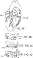
- FIGS. 3A, 3B, 3C and 3D provide an alternative view of the function of cerclage annuloplasty protection device 20.
- FIG. 3A shows the external anatomy of the heart, with coronary sinus 50 extending over a circumflex branch 52 of a left coronary artery 54.
- FIG. 3B shows an enlarged view of the overlapping relationship of coronary sinus 50 to coronary artery 52.
- FIG. 3C illustrates tension element 22 placed under tension during cerclage annuloplasty which is compressing underlying coronary artery 52 and interfering with myocardial perfusion.
- FIG. 3D shows tensioning material 22 extending through protection device 20 which is inhibiting the application of compressive force to coronary artery 52 which therefore remains patent and able to normally perfuse myocardial tissue.
- FIG. 1B An alternative embodiment of the protection device is shown in FIG. 1B , in which a protection device 54 is tubular so that an internal lumen extends through it to accommodate tension material 22.
- this embodiment is shaped into a generally arcuate (for example parabolic or catenary shape instead of semi-circular) arch 56.
- the distance d2 spanned by arch 58 is slightly greater than the distance d1 spanned by arch 24 in the embodiment of FIG. 3A because of the more gradual slope of arch 44.
- Protection device 54 of FIG. 3 also does not have the support feet of the embodiment shown in FIG. 3A , and compressive forces are distributed directly from proximal and distal ends 58, 59 of protection device 50 to a wall of the coronary sinus at a position other than over an underlying coronary artery.
- the protection device can assume a variety of shapes and configurations that support the tensioning material away from an underlying coronary artery.
- the protection device can be pre-shaped to the desired configuration, or it can be made of a memory alloy material that is generally linear when being advanced through the guidance catheter but assumes the desired protection device shape once it is deployed from the guidance catheter over the tensioning material.
- the protective device can take the form of a support or bridge having an open top on which the tensioning material is supported.
- the support would preferably have side guides (such as curved or upright members) that help retain the tensioning material on the support by resisting lateral forces that could dislodge the tensioning material from the support, while permitting longitudinal movement of the tensioning material along the support.
- Regurgitation (leakage) of the mitral valve or tricuspid valve can result from many different causes, such as ischemic heart disease, myocardial infarction, acquired or inherited cardiomyopathy, congenital defect, traumatic injury, infectious disease, and various forms of heart disease.
- Primary heart muscle disease can cause valvular regurgitation through dilation, resulting in expansion of the valvular annulus leading to malcoaptation of the valve leaflets through overstretching, degeneration, or rupture of the papillary muscle apparatus, or through dysfunction or malpositioning of the papillary muscles.
- This regurgitation can cause heart rhythm abnormalities such as atrial fibrillation, which itself can cause inexorable deterioration in heart muscle function. Such deterioration can be associated with functional impairment, congestive heart failure and significant pain, suffering, lessening of the quality of life, or even premature death.
- a less dangerous, minimally invasive procedure permits more patients to undergo mechanical treatment of valvular regurgitation.
- catheter-based heart-valve procedures are suitable for a broader population of patients.
- devices according to the claims for catheter-based valve repair that can be used to repair damaged or malfunctioning cardiac valves, for instance, by re-apposing valve leaflets by percutaneous-cerclage annuloplasty (reconstruction or augmentation of the ring or annulus of a defective cardiac valve).
- percutaneous cerclage annuloplasty is used to deliver circumferential or radial tensioning devices. Examples of some of these procedures are described in detail in WO2004/045378 and US 2005/0216039 .
- the system used to carry out an annuloplasty procedure can include a guiding catheter (GC), such as a preformed transjugular balloon-tipped guiding catheter which is introduced into the coronary (venous) sinus.
- a retrograde coronary radiocontrast venogram pressurizes and visualizes the great cardiac vein and septal perforator veins.
- a high performance guidewire designed for coronary artery recanalization may be steered using a deflectable microcatheter into the great cardiac vein and thereafter into a basal septal perforator vein.
- an annuloplasty procedure also can include using an imaging system to image the internal bodily tissues, organs, structures, cavities, and spaces of the subject being treated.
- transmitter or receiver coils can be used to facilitate active-device navigation using an imaging system, such as magneticresonance imaging (MRI).
- MRI magneticresonance imaging
- This imaging can be conducted along arbitrary or predetermined planes using various imaging methods based on X-ray technologies, X-ray fluoroscopy, MRI, electromagnetic-positron navigation, video technologies (such as endoscopy, arthroscopy, and the like), ultrasound, and other such technologies.
- real-time MRI rtMRI
- intracardiac ultrasound or electromagnetic guidance is employed.
- a particularly useful adjunct in cerclage annuloplasty is XFM, in which X-Ray is used with MRI to target myocardial structures, for example to help guide the annuloplasty wire in its trajectory through the structures of the heart.
- the XFM technique is disclosed, for example, in de Silva et al., Circulation 114:2342-2350 (2006 ).
- the guiding catheter enables percutaneous access into a subject's body, for example, percutaneous access to the heart, such as a chamber of the heart through an arm, neck, or leg vein.
- the guiding catheter is designed for access to the ventricle and/or atrium of the heart.
- the guiding catheter permits introduction of one or more secondary catheters, including a valve-manipulation catheter or microcatheter or canalization-needle catheter.
- the secondary catheter (or catheters) is used to treat, affect, or manipulate an organ, tissue, or structure of interest in the subject's body, such as the heart or particular structures within the heart.
- the guiding catheter permits introduction of one or more secondary catheters, such as a valve-manipulation catheter, into the heart while maintaining hemostasis.
- the secondary catheters may be coaxial or adjacent to each other, or may be introduced from multiple points of access outside the body.
- Guiding catheters are available in different shapes to suit the appropriate component of the mitral-valve-repair procedure.
- guiding catheter shapes can be provided to suit different coronary sinuses with different radii of curvature, to suit different coronary veins, transaortic as well as transseptal access routes, or to suit atria and ventricles of different calibers. All such shapes can be accommodated with appropriate primary, secondary, and tertiary curves.
- Examples of catheter configurations suitable to perform percutaneous transvascular mitral valve annuloplasty are know in the art and described in detail in U.S. Patent Publication No. 2005/0216039 .
- the guiding catheter can be introduced into a vein, such as the femoral or jugular vein, and guided through the inferior or superior vena cava into the right ventricle of the heart.
- the first trajectory (labeled a "simple” or “RV" trajectory) is one in which the annuloplasty wire enters the right atrium through the superior vena cava and is then introduced through the coronary ostium into the coronary sinus.
- the wire is advanced through the great cardiac vein into a basal blood vessel, such as a basal septal perforator vein.
- the wire then exits the septal perforator vein through myocardial interstitium into the right ventricle, re-entering the right atrium along the septal tricuspid valve commisure (at the intersection of the anterior cusp and the septal cusp).
- the guidewire is then retrieved using, for example, a vascular snare, and the guiding catheter and guidewire are replaced with a different tensioning system, such as a tensioning suture.
- the replacement can occur, for example, by attaching the tensioning material to the guidewire and advancing the tensioning material along the path of the guidewire as the guidewire is withdrawn.
- the protection device is then introduced through the guiding catheter over or in tandem with the tensioning system so as to protect an underlying coronary artery when tension is introduced to perform the annuloplasty.
- the location of the jeopardized coronary artery is identified, for example, by radiocontrast angiography.
- coronary veins are entered in the opposite direction from the right atrium or right ventricle under imaging guidance into a branch of the coronary sinus.
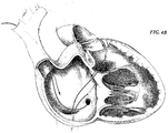
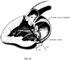
- FIG. 4A and 4B An alternative or “complex" right atrial cerclage trajectory shown in FIG. 4A and 4B extends further posterior through the basal septal myocardium into the right atrium near the coronary sinus.
- the wire traverses deep tissue of the septum moving in a posterior direction and exits above the opening of the coronary sinus.
- the plane of the resulting cerclage annuloplasty is shown in FIG. 4C to be related to and in the plane of the coronary sinus 60 such that annuloplasty remains uniquely feasible even if the coronary sinus is remote from the mitral valve annuloplasty.
- the plane of cerclage 60 enhances mitral valve coaptation, even when the coronary sinus is geometrically remote from the mitral valve annulus, because it is "tilted" toward the left ventricular outflow tract.
- the illustrated angle ⁇ between the cerclage plane 60 and the plane of the mitral valve annulus 62 is therefore advantageous.
- the illustrated trajectories of the cerclage annuloplasty induces reciprocal mitral valve coaptation and left ventricular outflow tract relaxation during ventricular systole.
- the guide wire is dimensioned to operate with the catheter and is usually longer than the guiding catheter.
- a guide wire of about 100 to about 250 centimeters in length and about 0.1 to about 2 mm in diameter can be used with the guiding catheter described above.
- a secondary catheter such as a tension delivery catheter, is intended for use with the guiding catheter, that secondary catheter also is dimensioned to operate with the guiding catheter and is usually longer than the guiding catheter.
- the guiding catheter can be made of any suitable material or combination of materials that provide both the strength and flexibility suitable to resist collapse by external forces, such as forces imposed during bending or twisting.
- Exemplary materials include, but are not limited to: polymers, such as polyethylene or polyurethane; carbon fiber; ceramic; or metals, such as nitinol, platinum, titanium, tantalum, tungsten, stainless steel, copper, gold, cobalt-chromium alloy, or nickel.
- the guiding catheter optionally can be composed of or reinforced with fibers of metal, carbon fiber, glass, fiberglass, a rigid polymer, or other high-strength material.
- the guiding catheter material is compatible with MRI, for example, braided nitinol, platinum, tungsten, gold, or carbon fiber.
- the exterior surfaces of the guiding catheter can be coated with a material or substance, such as Teflon® or other lubricous material that aids with the insertion of the guiding catheter into the body of the subject and/or aids in the movement of the guiding catheter through the subject's body.
- the guiding catheter can include a deflectable tip, such as a simple deflectable tip having a single degree of axial freedom.
- a deflectable tip such as a simple deflectable tip having a single degree of axial freedom.
- Exemplary (non-limiting) fixed-fulcrum and moveable-fulcrum-deflectable-tip catheters are commercially available, such as the deflectable-tip catheters described in U.S. Pat. Nos. 5,397,321 ; 5,487,757 ; 5,944,689 ; 5,928,191 ; 6,074,351 ; 6,198,974 ; and 6,346,099 .
- any suitable fixed-fulcrum or moveable-fulcrum deflectable-tip catheter can be adapted for use as a guiding catheter disclosed herein.
- the guiding catheter also can include structures or mechanisms for aiding in the rotation of the catheter about its longitudinal axis.
- the guiding catheter can include a guide collar, handgrip, handle, and other structures or devices at its proximal end that aid in operation of the guiding catheter.
- Various control mechanisms including electrical, optical, or mechanical control mechanisms, can be attached to the catheter via a guide collar.
- a guide wire can be included as a mechanical control mechanism.
- the guide collar can include additional operational features, such as a grip for aiding manual control of the guiding catheter, markers indicating the orientation of the guiding catheter lumen or subdivided lumens, markers to gauge the depth of guiding catheter advancement, instruments to measure guiding catheter operation or physiological signs of the subject (for example, a temperature gauge or pressure monitor), or an injector control mechanism coupled to the guiding catheter lumen for delivering a small, precise volume of injectate.
- the guide collar contains instrumentation electrically coupled to metallic braiding within the guiding catheter, thus allowing the guiding catheter to simultaneously be used as a receiver coil for MRI.
- a guide wire used with the system for guiding the guiding catheter into and through a subject's body can be composed of any suitable material, or combination of materials, including the materials described above in relation to the guiding catheter.
- Exemplary (non-limiting) guide wires are composed of material having the strength and flexibility suitable for use with the device, such as a strand of metal (for example, surgical stainless steel, nitinol, platinum, titanium, tungsten, copper, or nickel), carbon fiber, or a polymer, such as braided nylon.
- Particular (non-limiting) guide wires are composed of a strand of Nitinol® or other flexible, kink-resistant material.
- the guiding catheter or guide wire can include an image-enhancing feature, structure, material, or apparatus, such as a radiopaque marker (for example, a platinum or tantalum band around the circumference of the guide wire) adjacent its distal end.
- a radiopaque marker for example, a platinum or tantalum band around the circumference of the guide wire
- the guide wire can include etchings or notches, or be coated with a sonoreflective material to enhance images obtained via intravascular, intracardiac, transesophogeal, or other ultrasound-imaging method.
- the guide wire can be coated with a T1-shortening or T2*-shortening agent to facilitate passive visualization using MRI.
- a fiber-optic secondary catheter can be inserted into and through a secondary-catheter lumen of the guiding catheter to assist in visualizing the position of the guide wire within the subject as a guide wire is deployed through the distal guide-wire lumen port.
- the guide wire and/or guiding catheter includes a structure, apparatus, or device at its distal tip useful for penetrating tissue, such as myocardial skeleton, muscle, or connective tissue.
- tissue such as myocardial skeleton, muscle, or connective tissue.
- the distal tip of the guide wire can be sharpened to a point for puncturing through tissue, or a secondary catheter having a coring mechanism or forceps at its distal tip can be used in conjunction with the guiding catheter.
- the guide wire can deliver radiofrequency or laser ablative energy to assist with traversal of tissue.
- the distal end of the guide wire is bent to provide a J-shaped or a pigtail-shaped tip to protect against perforation of tissue by the guide wire during manipulation.
- the guide wire itself has a deflectable tip to facilitate traversal of tissue irrespective of natural tissue planes.
- One or more secondary catheters can be deployed within the lumen of the guiding catheter.
- each secondary catheter has a proximal end and a distal end; however, not all secondary catheters have a lumen.
- non-lumen secondary catheters can include various probes, such as temperature probes, radiofrequency or cryogenic ablation probes, or solid needles.
- An exemplary non-limiting secondary catheter is a canalization needle catheter, which can be deployed through the guiding catheter and into a chamber of the heart to place cerclage annuloplasty ligature through the coronary sinus around the mitral valve.
- a canalization-needle catheter is a type of secondary catheter that can be used to apply a suture to a bodily tissue, organ, or structure of interest.
- Ligatures used for the sutures described herein can be composed of any suitable material, such as surgical cotton, cotton tape, linen, or other natural fiber; nylon, polyester, or other polymer; metal, such as surgical stainless steel or nitinol; carbon fiber; or surgical gut.
- Ligature materials can be used in a woven, braided, or monofilament form. Suitable ligature and suture materials are commercially available from Ethicon, Inc. (Somerville, N.J.) and other companies.
- Tension is applied via the annuloplasty cerclage through, for example, suture material exchanged for the cerclage guidewire. Tension can be applied through both ends of the suture as they are externalized at the point of vascular access. Tension is applied under imaging guidance until the desired degree of mitral annular circumferential reduction is accomplished, or until the mitral valve regurgitation is reduced, or until other deleterious endpoints are achieved such as mitral valve inflow obstruction. Tension is secured using a knot or using a tension fixation device applied to both ends of the suture at the right atrium or right ventricle where the two cerclage trajectories cross, or at the point of vascular access, or in between the two. Tension is delivered by counterpressure against the fixation device, for example, applied through a delivery catheter. Before fixation, tension can be released or reduced, for example, to reposition the protection device or to achieve a lower degree of mitral annular circumferential reduction.
- valvular regurgitation is assessed repeatedly and noninvasively by an appropriate imaging technique.
- imaging techniques include X-ray angiography, electromagnetic position detection, MRI, external or intracavitary or intravascular ultrasound, X-ray computed tomography, pressure transducers in an affected chamber such as the left atrium or the pulmonary vein or the pulmonary artery, or a "fusion" or combination of any of the above.
- Example 1 Annuloplasty using protective device with percutaneous transluminal coronary angioplasty wire for cerclage
- This Example demonstrates the efficacy of one embodiment of the protective device in protecting the coronary artery from compression during trans-sinus annuloplasty.
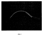
- the protective device was constructed of a stainless-steel hypotube ( FIG. 5 ).
- a 57 kg Yucatan pig was anesthetized, and after obtaining vascular access in the right jugular vein, the femoral vein, and the femoral artery, an annuloplasty wire (0.014 conventional percutaneous transluminal coronary angioplasty (PTCA) wire) was positioned around the mitral annulus to form a cerclage using the method described herein in which tensioning material passes through the coronary sinus over a coronary artery.
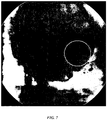
- FIG. 6 shows the left coronary angiogram of the subject with the wire in position, but before tension was applied.
- the protective device was positioned over the left circumflex artery branch, the coronary constriction was reduced to 1.5mm of minimal luminal diameter of left circumflex artery when the same tension was applied to the wire ( FIG. 8 ).
- the protective device protected the coronary artery from extrinsic compression during trans-sinus annuloplasty.
- the pressure in the left circumflex artery was measured using a conventional coronary pressure wire (Radi pressure wire).
- a 65 kg Yucatan pig was anesthetized, and after obtaining vascular access in the right jugular vein, the femoral vein, and the femoral artery, an annuloplasty wire (0.014 conventional PTCA wire) was positioned around the mitral annulus to form a cerclage essentially as described in Example 1.
- the pressure wire was positioned at a site in the left circumflex artery that was distal to the point where the cerclage passed over the coronary artery.
- Distal coronary pressure was measured while tension was applied with and without the protective device in place over the left circumflex artery branch.
- the protective device ameliorated the reduction in distal coronary artery pressure caused by the tension in the cerclage.
- This Example demonstrates the efficacy of another alternate embodiment of the protective device.
- the protective device was modified to augment the height of the central curve, and thereby further protect the coronary artery from compression during annuloplasty.
- a 74 kg Yucatan pig was anesthetized, and after obtaining vascular access in the right jugular vein, the femoral vein, and the femoral artery, an annuloplasty wire (0.014 conventional PTCA wire) was positioned around the mitral annulus to form a cerclage essentially as described in Example 1.
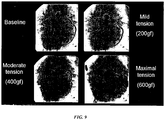
- FIG. 9 is a series of angiograms that show the effect on blood flow through the left circumflex artery when mild, moderate, and maximal tension was applied to the wire without the protective device in position.
- the protective device was then positioned over the left circumflex artery branch and the same tensions were applied to the cerclage wire. While the phenomenon of coronary pinching became more pronounced as the tension increased, use of the protective device completely abated the drop in blood pressure that was observed when the protective device was not used ( FIG. 10 ).
- the augmented height of the curve of the protective device in this embodiment improved the angiographic protection effect as compared to the protective devices of Examples 1 and 2.
- Example 4 Use of the protective device with a suture cerclage
- This Example demonstrates the efficacy of the protective device when used with a suture cerclage instead of a PTCA wire.
- a biocompatible suture material is a suitable cerclage ligature in many applications, however the metallic PTCA wire used in Examples 1-3 has different properties than a biocompatible suture.
- the device was tested during a suture-based cerclage annuloplasty.
- a 55 kg Yorkshire pig was anesthetized, and after obtaining vascular access in the right jugular vein, the femoral vein, and the femoral artery, an annuloplasty wire (0.014 conventional PTCA wire) was positioned around the mitral annulus to form a cerclage essentially as described in Example 1. This procedure was then repeating using a conventional surgical suture that was made of a non-absorbable black mono nylon with a thickness of 0.036cm (0.014 inches).
- the dimensions of the protective device were altered and the device was made from nitinol which is MR1-compatible.
- the width and height of the device were 1.361 cm (0.536”) and 0.3924cm (0.1545”) respectively, and the diameter of inner lumen and outer surface were 0.076cm (0.030”) and 0.114cm (0.045”) respectively.
- Tension was applied using the same method described in Examples 1-3. When tension was applied, a focal segment of proximal left circumflex artery was completely obstructed.
- the protective device was positioned over the left circumflex artery branch via delivering catheter and tension was applied as described above.
- This embodiment of the protective device afforded complete protection (no coronary compression) at comparable annuloplasty cerclage tensions.
- this embodiment of the protection device completely prevents coronary artery compression when used in combination with a sature cerclage.
- the protection device has been disclosed for use in a cerclage annuloplasty technique.
- the protective device can be used with any other annuloplasty device that extends even partially through the coronary sinus in a region that crosses an underlying coronary artery.
- the protective device can be used to protect against compression of coronary arteries with any coronary sinus annuloplasty device, such as the coronary sinus device in U.S. Patent No. 7,090,695 or the inflatable coronary sinus device shown in U.S. Patent No. 10/787,574 ( U.S. Patent Publication No. 2004/0254600 ).
- the protection device disclosed herein can also be used with annuloplasty devices that are implanted using an open-chest surgical repair instead of a catheter based approach.
- the protective device disclosed herein may be used to avoid that problem.
- the invention disclosed herein is not limited to a protective device for use with cerclage annuloplasty, nor is it limited to use of the device with catheter based delivery techniques.
- the protective device can be provided as an integral part of the implant or as a separate device suitable for placement between the implant and an underlying coronary artery to be protected.
- the implant When provided as an integral part of the implant, the implant is positioned in the coronary sinus so that the arch of the support extends over the underlying coronary artery.
- the protection device is provided as a separate device that is advanced through the catheter system over the tensioning material until it is positioned over the coronary artery to be protected.
Landscapes
- Health & Medical Sciences (AREA)
- Cardiology (AREA)
- Oral & Maxillofacial Surgery (AREA)
- Transplantation (AREA)
- Engineering & Computer Science (AREA)
- Biomedical Technology (AREA)
- Heart & Thoracic Surgery (AREA)
- Vascular Medicine (AREA)
- Life Sciences & Earth Sciences (AREA)
- Animal Behavior & Ethology (AREA)
- General Health & Medical Sciences (AREA)
- Public Health (AREA)
- Veterinary Medicine (AREA)
- Prostheses (AREA)
- Surgical Instruments (AREA)
Claims (14)
- Un dispositif de protection (20, 54) pour protéger un vaisseau de la compression au cours d'une annuloplastie mitrale par cathéter dans lequel un dispositif de tension d'annuloplastie s'étend au moins en partie à travers un sinus coronaire (50, 60) du coeur par-dessus une surface extérieure d'une artère coronaire (52), le dispositif (20, 54) comprenant :un dispositif de protection chirurgicalement stérile (20, 54) configuré pour passer au travers d'un cathéter transvasculaire et tenir à l'intérieur du sinus coronaire (50, 60) quand il passe par-dessus une artère coronaire (52), dans lequel un élément de tension annuloplastique (22) peut s'étendre et être placé sous tension,caractérisé par le fait que le dispositif de protection (20, 54) comprend en sus un pont central (24, 56, 58) de rigidité et dimensions suffisantes pour inhiber l'application de pression sur l'artère coronaire sous-jacente (52) quand l'élément de tension annuloplastique (22) est mis sous tension au cours d'une annuloplastie mitrale, le pont central (24, 56, 58) étant configuré pour s'étendre entre une extrémité proximale (26, 58) et une extrémité distale (28, 59) du dispositif de protection (20, 54) qui sont sensiblement colinéaires l'une avec l'autre de manière à ce que les extrémités proximale (26, 58) et distale (28, 59) forment des organes stabilisateurs.
- Le dispositif (20, 54) de la revendication 1, dans lequel les organes stabilisateurs sont des pieds stabilisateurs (30, 32).
- Le dispositif (20, 54) de la revendication 1, dans lequel le pont central (24, 56, 58) couvre une distance linéaire à sa base de 1,27 cm à 1,52 cm (0,5 pouce à 0,6 pouce).
- Le dispositif (20, 54) de la revendication 1, dans lequel le pont central (24, 56, 58) couvre une distance linéaire à sa base de 1,32 cm à 1,40 cm (0,52 pouce à 0,55 pouce).
- Le dispositif (20, 54) de la revendication 1, dans lequel le pont central (24, 56, 58) couvre une distance linéaire à sa base de 1,361 cm (0,536 pouce).
- Le dispositif (20, 54) de la revendication 1, dans lequel le pont central (24, 56, 58) a une hauteur de 0,38 cm à 0,41 cm (0,15 pouce to 0,16 pouce).
- Le dispositif (20, 54) de la revendication 1, dans lequel le pont central (24, 56, 58) a une hauteur de 0,3924 cm (0,1545 pouce).
- Le dispositif (20, 54) de la revendication 1, dans lequel le dispositif (20, 54) est tubulaire, a une première extrémité et une deuxième extrémité, et a un diamètre extérieur de 0,10 cm à 0,13 cm (0,04 à 0,05 pouce), et un diamètre intérieur de 0,064 cm à 0,089 cm (0,025 pouce à 0,035 pouce) sur toute sa longueur.
- Le dispositif (20, 54) de la revendication 8, dans lequel le dispositif (20, 54) a un diamètre extérieur de 0,114 cm (0,045 pouce) sur toute sa longueur, et le diamètre de la lumière intérieure est de 0,064 cm à 0,089 cm (0,025 pouce à 0,035 pouce) sur toute sa longueur.
- Le dispositif (20, 54) de la revendication 8, dans lequel la distance entre la première extrémité et la deuxième extrémité est de (0,536 pouce), la hauteur de la partie centrale est de 0,3924 cm (0,1545 pouce), le diamètre extérieur est de 0,114 cm (0,045 pouce), et le diamètre de la lumière intérieure est de 0,076 cm (0,030 pouce).
- Le dispositif (20, 54) de la revendication 1, le dispositif (20, 54) comprenant un matériau à mémoire de forme, de préférence le nitinol.
- Un dispositif (20, 54) selon une quelconque des revendications précédentes pour utilisation dans un procédé destiné à réparer une valve mitrale chez un patient, le procédé comprenant les étapes consistant à :introduire un élément de tension annuloplastique circonférentiel (22) au moins en partie à travers le sinus coronaire (50, 60) et par-dessus l'artère coronaire (52), l'élément de tension annuloplastique circonférentiel (22) exerçant une force de compression sur l'artère coronaire (52) ;déterminer l'endroit où le sinus coronaire (50, 60) passe par-dessus une artère coronaire (52) ; etinterposer le dispositif entre l'élément annuloplastique circonférentiel (22) et l'artère coronaire (52) à protéger, de préférence dans lequel l'étape consistant à déterminer l'endroit où le sinus coronaire (50, 60) passe au-dessus d'une artère coronaire (52) comprend l'exécution d'une angiographie de l'artère coronaire et éventuellement du sinus coronaire (50, 60) si nécessaire.
- Le dispositif (20, 54) de la revendication 12, dans lequel l'introduction de l'élément annuloplastique (22) comprend les étapes consistant à placer un élément de tension annuloplastique circonférentiel (22) à travers le sinus coronaire (50, 60), l'élément circonférentiel annuloplastique (22) s'étendant de préférence dans un plan d'annuloplastie qui est penché vers le tractus de sortie ventriculaire par comparaison à un plan d'annuloplastie de valve mitrale,
et placer l'élément de tension (22) sous tension, l'introduction de l'élément circonférentiel de tension (22) à travers le sinus coronaire (50, 60) comprenant de préférence les étapes consistant à :introduire l'élément de tension (22) dans le sinus coronaire (50, 60) à travers un cathéter ventriculaire ;placer le dispositif de protection (20, 54) sur l'élément de tension (22) par-dessus l'artère coronaire (52) ; etaugmenter la tension sur l'élément de tension (22) pour réduire une circonférence de l'anneau de valve mitrale, améliorant ainsi la fonction de la valve mitrale chez le sujet tout en protégeant l'écoulement continu du sang dans l'artère coronaire (52), l'introduction de l'élément de tension (22) au moins en partie autour de l'anneau de valve mitrale comprenant de préférence l'étape consistant à faire avancer un cathéter endovasculaire à travers le système vasculaire du sujet jusqu'au coeur, et à introduire l'élément de tension (22) et le dispositif (20, 54) depuis le cathéter en direction antégrade vers le sinus coronaire (50, 60) à travers un ostium de sinus coronaire, ou en direction rétrograde à travers une trajectoire annuloplastique de cerclage, l'élément de tension (22) étant de préférence une ligature, la ligature comprenant de préférence un matériau de suture. - Le dispositif (20, 54) de la revendication 12, dans lequel l'introduction de l'élément annuloplastique circonférentiel (22) au moins en partie à travers le sinus coronaire (50, 60) et par-dessus l'artère coronaire (52) comprend les étapes consistant à :insérer par voie percutanée un cathéter de guidage dans le système vasculaire d'un sujet, le cathéter de guidage ayant une extrémité proximale, une extrémité distale et une lumière ;faire avancer l'extrémité distale du cathéter de guidage à travers le système vasculaire pour positionner l'extrémité distale du cathéter de guidage en position adjacente à un sinus coronaire (50, 60) ; et(a) faire avancer un fil à travers le cathéter jusque dans le sinus coronaire (50, 60) jusqu'à une branche de veine coronaire telle qu'une veine perforante septale proximale, et ensuite à travers le tissu myocardique ou fibreux du coeur jusqu'à l'atrium droit au ventricule droit ;échanger le fil pour introduire du matériau de tension à travers le sinus coronaire (50, 60), et appliquer une tension sur le matériau de tension pour modifier la forme de la valve mitrale et réduire la régurgitation mitrale ; ou(b) faire avancer un fil à travers le cathéter jusque dans le sinus coronaire (50, 60) jusqu'à une branche de veine coronaire telle qu'une veine cardiaque antérolatérale, et ensuite à travers le tissu myocardique ou fibreux du coeur à travers la chambre ventriculaire gauche, et plus loin à travers le myocarde jusque dans la cavité ventriculaire droite ou atriale droite ;échanger le fil pour introduire du matériau de tension à travers le sinus coronaire (50, 60), et appliquer une tension sur le matériau de tension pour modifier la forme du coeur ou des valves et réduire un remodelage cardiaque indésirable ou une régurgitation valvulaire, de préférence comprenant en sus l'étape consistant à déterminer l'endroit où le matériau de tension dans le sinus coronaire (50, 60) passe par-dessus une artère coronaire (52) du coeur, et faire avancer le dispositif de protection (20, 54) à travers le cathéter pour le positionner entre le matériau de tension et l'artère coronaire (52).
Applications Claiming Priority (3)
| Application Number | Priority Date | Filing Date | Title |
|---|---|---|---|
| US85871606P | 2006-11-14 | 2006-11-14 | |
| US93261107P | 2007-05-31 | 2007-05-31 | |
| PCT/US2007/023876 WO2008060553A1 (fr) | 2006-11-14 | 2007-11-13 | Annuloplastie de valve mitrale réalisée par transcathéter dans le sinus coronaire et dispositif de protection de l'artère coronaire et du myocarde |
Publications (2)
| Publication Number | Publication Date |
|---|---|
| EP2091465A1 EP2091465A1 (fr) | 2009-08-26 |
| EP2091465B1 true EP2091465B1 (fr) | 2018-01-31 |
Family
ID=39226618
Family Applications (1)
| Application Number | Title | Priority Date | Filing Date |
|---|---|---|---|
| EP07861997.0A Active EP2091465B1 (fr) | 2006-11-14 | 2007-11-13 | Dispositif de protection de l'artère coronaire et du myocarde |
Country Status (3)
| Country | Link |
|---|---|
| US (2) | US8211171B2 (fr) |
| EP (1) | EP2091465B1 (fr) |
| WO (1) | WO2008060553A1 (fr) |
Cited By (15)
| Publication number | Priority date | Publication date | Assignee | Title |
|---|---|---|---|---|
| US10856984B2 (en) | 2017-08-25 | 2020-12-08 | Neovasc Tiara Inc. | Sequentially deployed transcatheter mitral valve prosthesis |
| US10940001B2 (en) | 2012-05-30 | 2021-03-09 | Neovasc Tiara Inc. | Methods and apparatus for loading a prosthesis onto a delivery system |
| US11311376B2 (en) | 2019-06-20 | 2022-04-26 | Neovase Tiara Inc. | Low profile prosthetic mitral valve |
| US11357622B2 (en) | 2016-01-29 | 2022-06-14 | Neovase Tiara Inc. | Prosthetic valve for avoiding obstruction of outflow |
| US11389291B2 (en) | 2013-04-04 | 2022-07-19 | Neovase Tiara Inc. | Methods and apparatus for delivering a prosthetic valve to a beating heart |
| US11413139B2 (en) | 2011-11-23 | 2022-08-16 | Neovasc Tiara Inc. | Sequentially deployed transcatheter mitral valve prosthesis |
| US11419720B2 (en) | 2010-05-05 | 2022-08-23 | Neovasc Tiara Inc. | Transcatheter mitral valve prosthesis |
| US11464631B2 (en) | 2016-11-21 | 2022-10-11 | Neovasc Tiara Inc. | Methods and systems for rapid retraction of a transcatheter heart valve delivery system |
| US11491006B2 (en) | 2019-04-10 | 2022-11-08 | Neovasc Tiara Inc. | Prosthetic valve with natural blood flow |
| US11497602B2 (en) | 2012-02-14 | 2022-11-15 | Neovasc Tiara Inc. | Methods and apparatus for engaging a valve prosthesis with tissue |
| US11602429B2 (en) | 2019-04-01 | 2023-03-14 | Neovasc Tiara Inc. | Controllably deployable prosthetic valve |
| US11737872B2 (en) | 2018-11-08 | 2023-08-29 | Neovasc Tiara Inc. | Ventricular deployment of a transcatheter mitral valve prosthesis |
| US11779742B2 (en) | 2019-05-20 | 2023-10-10 | Neovasc Tiara Inc. | Introducer with hemostasis mechanism |
| US11998447B2 (en) | 2019-03-08 | 2024-06-04 | Neovasc Tiara Inc. | Retrievable prosthesis delivery system |
| US12109111B2 (en) | 2015-12-15 | 2024-10-08 | Neovasc Tiara Inc. | Transseptal delivery system |
Families Citing this family (92)
| Publication number | Priority date | Publication date | Assignee | Title |
|---|---|---|---|---|
| US9943409B2 (en) * | 2006-11-14 | 2018-04-17 | The United States Of America, As Represented By The Secretary, Department Of Health And Human Services | Transcatheter coronary sinus mitral valve annuloplasty procedure and coronary artery and myocardial protection device |
| KR101116867B1 (ko) | 2009-08-28 | 2012-03-06 | 김준홍 | 관상정맥동과 삼천판막의 조직보호기구, 매듭 전달 기구 및 이들을 포함하는 승모판막 서클라지 시술용 장치 |
| KR101231140B1 (ko) * | 2011-08-12 | 2013-02-07 | 부산대학교 산학협력단 | 승모판막 서클라지 시술용 장치 |
| US9579200B2 (en) | 2010-09-15 | 2017-02-28 | The United States Of America, As Represented By The Secretary, Department Of Health & Human Services | Methods and devices for transcatheter cerclage annuloplasty |
| BR112013007253B1 (pt) * | 2010-09-29 | 2021-10-05 | Taupnumedical Co.,Ltd | Dispositivo de proteção tecidual para seio coronariano e válvula tricúspide, dispositivo de distribuição de nó e dispositivo para cerclagem de válvula mitral, contendo o mesmo |
| CA3035048C (fr) | 2010-12-23 | 2021-05-04 | Mark Deem | Systeme de reparation et remplacement de valvule mitrale |
| US8454656B2 (en) | 2011-03-01 | 2013-06-04 | Medtronic Ventor Technologies Ltd. | Self-suturing anchors |
| AU2012272855C1 (en) | 2011-06-21 | 2018-04-05 | Twelve, Inc. | Prosthetic heart valve devices and associated systems and methods |
| AU2012325809B2 (en) | 2011-10-19 | 2016-01-21 | Twelve, Inc. | Devices, systems and methods for heart valve replacement |
| US9655722B2 (en) | 2011-10-19 | 2017-05-23 | Twelve, Inc. | Prosthetic heart valve devices, prosthetic mitral valves and associated systems and methods |
| US11202704B2 (en) | 2011-10-19 | 2021-12-21 | Twelve, Inc. | Prosthetic heart valve devices, prosthetic mitral valves and associated systems and methods |
| CA2849030C (fr) | 2011-10-19 | 2020-10-27 | Twelve, Inc. | Dispositifs de valvules cardiaques prothetiques, valvules mitrales prothetiques et systemes et procedes associes |
| US9039757B2 (en) | 2011-10-19 | 2015-05-26 | Twelve, Inc. | Prosthetic heart valve devices, prosthetic mitral valves and associated systems and methods |
| US9763780B2 (en) | 2011-10-19 | 2017-09-19 | Twelve, Inc. | Devices, systems and methods for heart valve replacement |
| US9579198B2 (en) | 2012-03-01 | 2017-02-28 | Twelve, Inc. | Hydraulic delivery systems for prosthetic heart valve devices and associated methods |
| JP6143425B2 (ja) * | 2012-06-11 | 2017-06-07 | 東芝メディカルシステムズ株式会社 | X線診断装置 |
| KR101296604B1 (ko) | 2012-09-05 | 2013-08-14 | 부산대학교 산학협력단 | 승모판 서클라지 시술용 시스 및 서클라지 실 |
| US10543088B2 (en) | 2012-09-14 | 2020-01-28 | Boston Scientific Scimed, Inc. | Mitral valve inversion prostheses |
| US10849755B2 (en) | 2012-09-14 | 2020-12-01 | Boston Scientific Scimed, Inc. | Mitral valve inversion prostheses |
| US9549666B2 (en) | 2012-11-10 | 2017-01-24 | Curvo Medical, Inc. | Coaxial micro-endoscope |
| US9233225B2 (en) | 2012-11-10 | 2016-01-12 | Curvo Medical, Inc. | Coaxial bi-directional catheter |
| EP2967857B1 (fr) * | 2013-03-14 | 2024-10-30 | The United States of America, as represented by The Secretary, Department of Health and Human Services | Dispositifs pour traiter la régurgitation valvulaire tricuspide fonctionnelle |
| WO2014189974A1 (fr) | 2013-05-20 | 2014-11-27 | Twelve, Inc. | Dispositifs de valvule cardiaque pouvant être implantée, dispositifs de réparation de valve mitrale, et systèmes et procédés associés |
| KR101467373B1 (ko) * | 2013-05-23 | 2014-12-10 | 부산대학교 산학협력단 | 승모판막 서클라지 시술을 위한 심근 보호용 스토퍼 및 이를 구비한 승모판막 서클라지 시술장치 |
| WO2014200764A1 (fr) | 2013-06-12 | 2014-12-18 | The United States Of America, As Represented By The Secretary, Department Of Health & Human Services | Systèmes de mise en place d'implants circulaires et procédés |
| WO2015010027A1 (fr) * | 2013-07-19 | 2015-01-22 | Volcano Corporation | Dispositifs, systèmes et procédés d'évaluation de vaisseaux |
| WO2015028986A1 (fr) * | 2013-08-29 | 2015-03-05 | June-Hong Kim | Système de capture de fil du tractus d'évacuation du ventricule droit en annuloplastie avec cerclage de la valvule mitrale |
| KR20150026766A (ko) | 2013-08-29 | 2015-03-11 | 김준홍 | 승모판막 서클라지 시술용 카테터 및 이를 이용한 유도방법 |
| KR101563172B1 (ko) * | 2014-05-20 | 2015-10-27 | (주) 타우피엔유메디칼 | 승모판막 서클라지 시술용 조직보호기구 |
| KR101581021B1 (ko) | 2014-05-28 | 2015-12-29 | (주) 타우피엔유메디칼 | 코일 스프링을 이용한 승모판막 서클라지 시술용 조직보호기구 및 이의 제조방법 |
| KR101581025B1 (ko) | 2014-06-16 | 2015-12-29 | (주) 타우피엔유메디칼 | 아치형 관상동맥 보호구가 일체화된 승모판막 서클라지 시술용 서클라지 로프 |
| KR20150144568A (ko) | 2014-06-17 | 2015-12-28 | (주) 타우피엔유메디칼 | 삼천판막 역류증 시술용 조직보호기구 |
| KR20160002107A (ko) | 2014-06-30 | 2016-01-07 | (주) 타우피엔유메디칼 | 탄성부를 갖는 승모판막 서클라지 시술용 조직보호기구 |
| US9180005B1 (en) | 2014-07-17 | 2015-11-10 | Millipede, Inc. | Adjustable endolumenal mitral valve ring |
| KR20160011381A (ko) | 2014-07-22 | 2016-02-01 | (주) 타우피엔유메디칼 | 승모판막 서클라지 와이어의 고정장치 및 방법 |
| KR20160026289A (ko) | 2014-08-29 | 2016-03-09 | (주) 타우피엔유메디칼 | 승모판막 서클라지 시술에서 심장내 관상동맥 보호구 일체형 로프와 가이드와이어의 교환용 카테터, 장치 및 교환 방법 |
| KR101677193B1 (ko) * | 2014-08-29 | 2016-11-17 | (주) 타우피엔유메디칼 | 승모판막 서클라지 관상정맥동 성형술에서 루프를 형성하기 위한 루프용 로프 |
| KR20160029548A (ko) | 2014-09-05 | 2016-03-15 | (주) 타우피엔유메디칼 | 삼첨판막 손상 방지용 카테터 |
| CN107530166B (zh) | 2015-02-13 | 2020-01-31 | 魅尔皮德股份有限公司 | 使用旋转锚固件的瓣膜置换 |
| JP7111610B2 (ja) | 2015-08-21 | 2022-08-02 | トゥエルヴ, インコーポレイテッド | 埋込可能な心臓弁デバイス、僧帽弁修復デバイス、ならびに関連するシステム及び方法 |
| US10335275B2 (en) | 2015-09-29 | 2019-07-02 | Millipede, Inc. | Methods for delivery of heart valve devices using intravascular ultrasound imaging |
| CN111329541B (zh) | 2015-11-17 | 2023-09-19 | 波士顿科学国际有限公司 | 用于使心脏瓣环重新定形的可植入装置和输送系统 |
| EP3448316B1 (fr) | 2016-04-29 | 2023-03-29 | Medtronic Vascular Inc. | Dispositifs de valve cardiaque prothétiques avec fils d'ancrage |
| KR102654995B1 (ko) * | 2016-05-06 | 2024-04-04 | 더 유나이티드 스테이츠 오브 어메리카, 애즈 리프리젠티드 바이 더 세크러테리, 디파트먼트 오브 헬쓰 앤드 휴먼 서비씨즈 | 고리성형술 절차들, 관련된 기기들 및 방법들 |
| US12544227B2 (en) | 2016-05-06 | 2026-02-10 | Transmural Systems Llc | Annuloplasty procedures, related devices and methods |
| US11980545B2 (en) | 2016-05-06 | 2024-05-14 | Transmural Systems Llc | Annuloplasty procedures, related devices and methods |
| US11007059B2 (en) | 2016-05-06 | 2021-05-18 | Transmural Systems Llc | Annuloplasty procedures, related devices and methods |
| US11039923B2 (en) | 2016-05-06 | 2021-06-22 | Transmural Systems Llc | Annuloplasty procedures, related devices and methods |
| US20200146854A1 (en) * | 2016-05-16 | 2020-05-14 | Elixir Medical Corporation | Methods and devices for heart valve repair |
| US11097057B2 (en) | 2016-07-22 | 2021-08-24 | Intuitive Surgical Operations, Inc. | Cannulas having wall strengthening features, and related systems and methods |
| KR101805679B1 (ko) | 2017-02-01 | 2017-12-06 | (주) 타우피엔유메디칼 | 삼첨판막 역류증 시술용 기구 |
| EP3579789B1 (fr) | 2017-02-10 | 2026-04-01 | Boston Scientific Scimed, Inc. | Dispositif implantable permettant de remodeler un anneau de valvule cardiaque |
| US10433961B2 (en) | 2017-04-18 | 2019-10-08 | Twelve, Inc. | Delivery systems with tethers for prosthetic heart valve devices and associated methods |
| US10575950B2 (en) | 2017-04-18 | 2020-03-03 | Twelve, Inc. | Hydraulic systems for delivering prosthetic heart valve devices and associated methods |
| US10702378B2 (en) | 2017-04-18 | 2020-07-07 | Twelve, Inc. | Prosthetic heart valve device and associated systems and methods |
| US10792151B2 (en) | 2017-05-11 | 2020-10-06 | Twelve, Inc. | Delivery systems for delivering prosthetic heart valve devices and associated methods |
| US10646338B2 (en) | 2017-06-02 | 2020-05-12 | Twelve, Inc. | Delivery systems with telescoping capsules for deploying prosthetic heart valve devices and associated methods |
| US10709591B2 (en) | 2017-06-06 | 2020-07-14 | Twelve, Inc. | Crimping device and method for loading stents and prosthetic heart valves |
| US10729541B2 (en) | 2017-07-06 | 2020-08-04 | Twelve, Inc. | Prosthetic heart valve devices and associated systems and methods |
| US10786352B2 (en) | 2017-07-06 | 2020-09-29 | Twelve, Inc. | Prosthetic heart valve devices and associated systems and methods |
| EP3672532B1 (fr) * | 2017-08-26 | 2022-08-03 | Transmural Systems LLC | Système de stimulation cardiaque implantable |
| US11026791B2 (en) | 2018-03-20 | 2021-06-08 | Medtronic Vascular, Inc. | Flexible canopy valve repair systems and methods of use |
| US11285003B2 (en) | 2018-03-20 | 2022-03-29 | Medtronic Vascular, Inc. | Prolapse prevention device and methods of use thereof |
| WO2019195860A2 (fr) | 2018-04-04 | 2019-10-10 | Vdyne, Llc | Dispositifs et procédés d'ancrage d'une valvule cardiaque transcathéter |
| KR102089363B1 (ko) * | 2018-04-09 | 2020-03-16 | (주) 타우피엔유메디칼 | 승모판막 시술용 와이어 연결장치 |
| US11344413B2 (en) | 2018-09-20 | 2022-05-31 | Vdyne, Inc. | Transcatheter deliverable prosthetic heart valves and methods of delivery |
| US12186187B2 (en) | 2018-09-20 | 2025-01-07 | Vdyne, Inc. | Transcatheter deliverable prosthetic heart valves and methods of delivery |
| US11278437B2 (en) | 2018-12-08 | 2022-03-22 | Vdyne, Inc. | Compression capable annular frames for side delivery of transcatheter heart valve replacement |
| US11071627B2 (en) | 2018-10-18 | 2021-07-27 | Vdyne, Inc. | Orthogonally delivered transcatheter heart valve frame for valve in valve prosthesis |
| US10595994B1 (en) | 2018-09-20 | 2020-03-24 | Vdyne, Llc | Side-delivered transcatheter heart valve replacement |
| US10321995B1 (en) | 2018-09-20 | 2019-06-18 | Vdyne, Llc | Orthogonally delivered transcatheter heart valve replacement |
| US11109969B2 (en) | 2018-10-22 | 2021-09-07 | Vdyne, Inc. | Guidewire delivery of transcatheter heart valve |
| US10653522B1 (en) | 2018-12-20 | 2020-05-19 | Vdyne, Inc. | Proximal tab for side-delivered transcatheter heart valve prosthesis |
| US11253359B2 (en) | 2018-12-20 | 2022-02-22 | Vdyne, Inc. | Proximal tab for side-delivered transcatheter heart valves and methods of delivery |
| WO2020146842A1 (fr) | 2019-01-10 | 2020-07-16 | Vdyne, Llc | Crochet d'ancrage pour prothèse de valvule cardiaque transcathéter à distribution latérale |
| US11273032B2 (en) | 2019-01-26 | 2022-03-15 | Vdyne, Inc. | Collapsible inner flow control component for side-deliverable transcatheter heart valve prosthesis |
| US11185409B2 (en) | 2019-01-26 | 2021-11-30 | Vdyne, Inc. | Collapsible inner flow control component for side-delivered transcatheter heart valve prosthesis |
| CA3132162A1 (fr) | 2019-03-05 | 2020-09-10 | Vdyne, Inc. | Dispositifs de regulation de regurgitation tricuspide pour prothese de valvule cardiaque transcatheter orthogonale |
| US10758346B1 (en) | 2019-03-14 | 2020-09-01 | Vdyne, Inc. | A2 clip for side-delivered transcatheter mitral valve prosthesis |
| US11076956B2 (en) | 2019-03-14 | 2021-08-03 | Vdyne, Inc. | Proximal, distal, and anterior anchoring tabs for side-delivered transcatheter mitral valve prosthesis |
| US11173027B2 (en) | 2019-03-14 | 2021-11-16 | Vdyne, Inc. | Side-deliverable transcatheter prosthetic valves and methods for delivering and anchoring the same |
| US10631983B1 (en) | 2019-03-14 | 2020-04-28 | Vdyne, Inc. | Distal subannular anchoring tab for side-delivered transcatheter valve prosthesis |
| KR102228627B1 (ko) | 2019-04-05 | 2021-03-16 | (주) 타우피엔유메디칼 | 접이식 관상동맥 보호구가 결합된 와이어 장치. |
| CN114072106B (zh) | 2019-05-04 | 2025-09-19 | 维迪内股份有限公司 | 用于在自体瓣环中部署侧面递送的假体心脏瓣膜的束紧装置和方法 |
| KR102240798B1 (ko) | 2019-05-31 | 2021-04-15 | (주) 타우피엔유메디칼 | 크기조절 및 각도조절이 가능한 삼첨판막 역류증 시술용 기구 |
| EP4480458B1 (fr) | 2019-08-20 | 2026-08-12 | VDyne, Inc. | Dispositifs d'administration pour valvules prothétiques transcathéter à pose latérale |
| CN114630665B (zh) | 2019-08-26 | 2025-06-17 | 维迪内股份有限公司 | 可侧面输送的经导管假体瓣膜及其输送和锚定方法 |
| WO2021146515A1 (fr) | 2020-01-17 | 2021-07-22 | Vdyne, Inc. | Éléments de stabilité ventriculaire pour valvules cardiaques prothétiques à administration latérale et procédés d'administration |
| CN115190781A (zh) * | 2020-02-20 | 2022-10-14 | Tau心脏公司 | 用于减少三尖瓣返流的经导管系统和方法 |
| US11872357B2 (en) | 2020-11-09 | 2024-01-16 | Agile Devices, Inc. | Devices for steering catheters |
| CN115737201B (zh) * | 2021-09-03 | 2026-04-21 | 瀚芯医疗科技(深圳)有限公司 | 二尖瓣环缩装置 |
| AU2023358759A1 (en) | 2022-10-14 | 2025-05-15 | Vdyne, Inc. | Devices and methods for delivering a prosthetic heart valve using supra-annular support |
Family Cites Families (38)
| Publication number | Priority date | Publication date | Assignee | Title |
|---|---|---|---|---|
| CA1303298C (fr) | 1986-08-06 | 1992-06-16 | Alain Carpentier | Prothese souple pour soutenir les valvules cardiaques |
| US4917698A (en) | 1988-12-22 | 1990-04-17 | Baxter International Inc. | Multi-segmented annuloplasty ring prosthesis |
| WO1990009153A1 (fr) | 1989-02-13 | 1990-08-23 | Baxter International Inc. | Anneau d'annuloplastie selectivement flexible |
| US5350420A (en) | 1989-07-31 | 1994-09-27 | Baxter International Inc. | Flexible annuloplasty ring and holder |
| US5041130A (en) | 1989-07-31 | 1991-08-20 | Baxter International Inc. | Flexible annuloplasty ring and holder |
| US5290300A (en) | 1989-07-31 | 1994-03-01 | Baxter International Inc. | Flexible suture guide and holder |
| US5064431A (en) | 1991-01-16 | 1991-11-12 | St. Jude Medical Incorporated | Annuloplasty ring |
| US5201880A (en) | 1992-01-27 | 1993-04-13 | Pioneering Technologies, Inc. | Mitral and tricuspid annuloplasty rings |
| US5972030A (en) | 1993-02-22 | 1999-10-26 | Heartport, Inc. | Less-invasive devices and methods for treatment of cardiac valves |
| US5450860A (en) | 1993-08-31 | 1995-09-19 | W. L. Gore & Associates, Inc. | Device for tissue repair and method for employing same |
| US5476528A (en) | 1993-12-20 | 1995-12-19 | Tennessee Valley Authority | System for improving material release profiles |
| CH691846A5 (fr) * | 1997-06-20 | 2001-11-15 | Ecole Polytech | Implant de dilatation intravasculaire à déflecteur. |
| US6024764A (en) * | 1997-08-19 | 2000-02-15 | Intermedics, Inc. | Apparatus for imparting physician-determined shapes to implantable tubular devices |
| JP2000169384A (ja) | 1998-12-09 | 2000-06-20 | Yuusu Techno Corporation:Kk | 血糖値上昇抑制乃至下降用組成物 |
| US7192442B2 (en) | 1999-06-30 | 2007-03-20 | Edwards Lifesciences Ag | Method and device for treatment of mitral insufficiency |
| US6402781B1 (en) | 2000-01-31 | 2002-06-11 | Mitralife | Percutaneous mitral annuloplasty and cardiac reinforcement |
| US20020128701A1 (en) * | 2000-04-28 | 2002-09-12 | Winters R. Edward | Low profile expandable hoop support device for flexible tubes |
| US20060106279A1 (en) * | 2004-05-14 | 2006-05-18 | Ample Medical, Inc. | Devices, systems, and methods for reshaping a heart valve annulus, including the use of a bridge implant having an adjustable bridge stop |
| US8956407B2 (en) * | 2000-09-20 | 2015-02-17 | Mvrx, Inc. | Methods for reshaping a heart valve annulus using a tensioning implant |
| US20050222489A1 (en) * | 2003-10-01 | 2005-10-06 | Ample Medical, Inc. | Devices, systems, and methods for reshaping a heart valve annulus, including the use of a bridge implant |
| US6800090B2 (en) | 2001-05-14 | 2004-10-05 | Cardiac Dimensions, Inc. | Mitral valve therapy device, system and method |
| US6726716B2 (en) | 2001-08-24 | 2004-04-27 | Edwards Lifesciences Corporation | Self-molding annuloplasty ring |
| DE60236755D1 (de) * | 2001-10-04 | 2010-07-29 | Neovasc Medical Ltd | Flussverringerndes implantat |
| US7144363B2 (en) * | 2001-10-16 | 2006-12-05 | Extensia Medical, Inc. | Systems for heart treatment |
| US6949122B2 (en) | 2001-11-01 | 2005-09-27 | Cardiac Dimensions, Inc. | Focused compression mitral valve device and method |
| US6764510B2 (en) * | 2002-01-09 | 2004-07-20 | Myocor, Inc. | Devices and methods for heart valve treatment |
| US7485143B2 (en) * | 2002-11-15 | 2009-02-03 | Abbott Cardiovascular Systems Inc. | Apparatuses and methods for heart valve repair |
| US20040098116A1 (en) * | 2002-11-15 | 2004-05-20 | Callas Peter L. | Valve annulus constriction apparatus and method |
| WO2004045378A2 (fr) | 2002-11-15 | 2004-06-03 | The Government Of The United States Of America As Represented By The Secretary Of Health And Human Services | Procede et dispositif de reparation par catheter de valvules cardiaques |
| US20040254600A1 (en) | 2003-02-26 | 2004-12-16 | David Zarbatany | Methods and devices for endovascular mitral valve correction from the left coronary sinus |
| US20040220657A1 (en) * | 2003-05-02 | 2004-11-04 | Cardiac Dimensions, Inc., A Washington Corporation | Tissue shaping device with conformable anchors |
| US20060184242A1 (en) | 2003-10-20 | 2006-08-17 | Samuel Lichtenstein | Method and apparatus for percutaneous reduction of anterior-posterior diameter of mitral valve |
| US7794496B2 (en) | 2003-12-19 | 2010-09-14 | Cardiac Dimensions, Inc. | Tissue shaping device with integral connector and crimp |
| US7357815B2 (en) | 2005-04-21 | 2008-04-15 | Micardia Corporation | Dynamically adjustable implants and methods for reshaping tissue |
| US7500989B2 (en) | 2005-06-03 | 2009-03-10 | Edwards Lifesciences Corp. | Devices and methods for percutaneous repair of the mitral valve via the coronary sinus |
| CN100445488C (zh) * | 2005-08-01 | 2008-12-24 | 邱则有 | 一种现浇砼成型用空腔构件 |
| US20070073391A1 (en) | 2005-09-28 | 2007-03-29 | Henry Bourang | System and method for delivering a mitral valve repair device |
| KR101116867B1 (ko) * | 2009-08-28 | 2012-03-06 | 김준홍 | 관상정맥동과 삼천판막의 조직보호기구, 매듭 전달 기구 및 이들을 포함하는 승모판막 서클라지 시술용 장치 |
-
2007
- 2007-11-13 WO PCT/US2007/023876 patent/WO2008060553A1/fr not_active Ceased
- 2007-11-13 US US12/514,990 patent/US8211171B2/en active Active
- 2007-11-13 EP EP07861997.0A patent/EP2091465B1/fr active Active
-
2012
- 2012-05-10 US US13/468,761 patent/US9271833B2/en active Active
Cited By (25)
| Publication number | Priority date | Publication date | Assignee | Title |
|---|---|---|---|---|
| US12611303B2 (en) | 2010-05-05 | 2026-04-28 | Neovasc Tiara Inc. | Transcatheter mitral valve prosthesis |
| US11419720B2 (en) | 2010-05-05 | 2022-08-23 | Neovasc Tiara Inc. | Transcatheter mitral valve prosthesis |
| US11413139B2 (en) | 2011-11-23 | 2022-08-16 | Neovasc Tiara Inc. | Sequentially deployed transcatheter mitral valve prosthesis |
| US12053369B2 (en) | 2011-11-23 | 2024-08-06 | Neovasc Tiara Inc. | Sequentially deployed transcatheter mitral valve prosthesis |
| US12138159B2 (en) | 2012-02-14 | 2024-11-12 | Neovasc Tiara Inc. | Methods and apparatus for engaging a valve prosthesis with tissue |
| US11497602B2 (en) | 2012-02-14 | 2022-11-15 | Neovasc Tiara Inc. | Methods and apparatus for engaging a valve prosthesis with tissue |
| US11617650B2 (en) | 2012-05-30 | 2023-04-04 | Neovasc Tiara Inc. | Methods and apparatus for loading a prosthesis onto a delivery system |
| US11389294B2 (en) | 2012-05-30 | 2022-07-19 | Neovasc Tiara Inc. | Methods and apparatus for loading a prosthesis onto a delivery system |
| US10940001B2 (en) | 2012-05-30 | 2021-03-09 | Neovasc Tiara Inc. | Methods and apparatus for loading a prosthesis onto a delivery system |
| US11389291B2 (en) | 2013-04-04 | 2022-07-19 | Neovase Tiara Inc. | Methods and apparatus for delivering a prosthetic valve to a beating heart |
| US12109111B2 (en) | 2015-12-15 | 2024-10-08 | Neovasc Tiara Inc. | Transseptal delivery system |
| US12193932B2 (en) | 2016-01-29 | 2025-01-14 | Neovasc Tiara Inc. | Prosthetic valve for avoiding obstruction of outflow |
| US11357622B2 (en) | 2016-01-29 | 2022-06-14 | Neovase Tiara Inc. | Prosthetic valve for avoiding obstruction of outflow |
| US11464631B2 (en) | 2016-11-21 | 2022-10-11 | Neovasc Tiara Inc. | Methods and systems for rapid retraction of a transcatheter heart valve delivery system |
| US12201524B2 (en) | 2016-11-21 | 2025-01-21 | Neovasc Tiara Inc. | Methods and systems for rapid retraction of a transcatheter heart valve delivery system |
| US11793640B2 (en) | 2017-08-25 | 2023-10-24 | Neovasc Tiara Inc. | Sequentially deployed transcatheter mitral valve prosthesis |
| US10856984B2 (en) | 2017-08-25 | 2020-12-08 | Neovasc Tiara Inc. | Sequentially deployed transcatheter mitral valve prosthesis |
| US11737872B2 (en) | 2018-11-08 | 2023-08-29 | Neovasc Tiara Inc. | Ventricular deployment of a transcatheter mitral valve prosthesis |
| US11998447B2 (en) | 2019-03-08 | 2024-06-04 | Neovasc Tiara Inc. | Retrievable prosthesis delivery system |
| US11602429B2 (en) | 2019-04-01 | 2023-03-14 | Neovasc Tiara Inc. | Controllably deployable prosthetic valve |
| US12036117B2 (en) | 2019-04-10 | 2024-07-16 | Neovasc Tiara Inc. | Prosthetic valve with natural blood flow |
| US11491006B2 (en) | 2019-04-10 | 2022-11-08 | Neovasc Tiara Inc. | Prosthetic valve with natural blood flow |
| US11779742B2 (en) | 2019-05-20 | 2023-10-10 | Neovasc Tiara Inc. | Introducer with hemostasis mechanism |
| US11931254B2 (en) | 2019-06-20 | 2024-03-19 | Neovasc Tiara Inc. | Low profile prosthetic mitral valve |
| US11311376B2 (en) | 2019-06-20 | 2022-04-26 | Neovase Tiara Inc. | Low profile prosthetic mitral valve |
Also Published As
| Publication number | Publication date |
|---|---|
| EP2091465A1 (fr) | 2009-08-26 |
| WO2008060553A1 (fr) | 2008-05-22 |
| US20100049314A1 (en) | 2010-02-25 |
| US9271833B2 (en) | 2016-03-01 |
| US8211171B2 (en) | 2012-07-03 |
| US20120232574A1 (en) | 2012-09-13 |
Similar Documents
| Publication | Publication Date | Title |
|---|---|---|
| US11925558B2 (en) | Coronary sinus mitral valve annuloplasty procedure and coronary artery and myocardial protection device | |
| US8211171B2 (en) | Transcatheter coronary sinus mitral valve annuloplasty procedure and coronary artery and myocardial protection device | |
| US12544228B2 (en) | Annuloplasty procedures, related devices and methods | |
| JP7530539B2 (ja) | インプラント | |
| WO2017151292A1 (fr) | Procédure d'annuloplastie de valvule mitrale de sinus coronaire transcathéter et dispositif de protection d'artère coronaire et de myocarde | |
| US11259926B2 (en) | Cardiac annuloplasty and pacing procedures, related devices and methods | |
| US11039923B2 (en) | Annuloplasty procedures, related devices and methods | |
| US11007059B2 (en) | Annuloplasty procedures, related devices and methods | |
| US20250325370A1 (en) | Cardiac annuloplasty procedures, related devices and methods | |
| US20150289976A1 (en) | Devices, Systems, and Methods for Reshaping a Heart Valve Annulus, Including the Use of a Bridge Implant Having an Adjustable Bridge Stop | |
| US12544227B2 (en) | Annuloplasty procedures, related devices and methods |
Legal Events
| Date | Code | Title | Description |
|---|---|---|---|
| PUAI | Public reference made under article 153(3) epc to a published international application that has entered the european phase |
Free format text: ORIGINAL CODE: 0009012 |
|
| 17P | Request for examination filed |
Effective date: 20090611 |
|
| AK | Designated contracting states |
Kind code of ref document: A1 Designated state(s): AT BE BG CH CY CZ DE DK EE ES FI FR GB GR HU IE IS IT LI LT LU LV MC MT NL PL PT RO SE SI SK TR |
|
| DAX | Request for extension of the european patent (deleted) | ||
| 17Q | First examination report despatched |
Effective date: 20120123 |
|
| GRAP | Despatch of communication of intention to grant a patent |
Free format text: ORIGINAL CODE: EPIDOSNIGR1 |
|
| RIC1 | Information provided on ipc code assigned before grant |
Ipc: A61F 2/06 20130101ALI20170717BHEP Ipc: A61M 25/00 20060101ALI20170717BHEP Ipc: A61F 2/24 20060101AFI20170717BHEP |
|
| INTG | Intention to grant announced |
Effective date: 20170822 |
|
| GRAS | Grant fee paid |
Free format text: ORIGINAL CODE: EPIDOSNIGR3 |
|
| GRAA | (expected) grant |
Free format text: ORIGINAL CODE: 0009210 |
|
| AK | Designated contracting states |
Kind code of ref document: B1 Designated state(s): AT BE BG CH CY CZ DE DK EE ES FI FR GB GR HU IE IS IT LI LT LU LV MC MT NL PL PT RO SE SI SK TR |
|
| REG | Reference to a national code |
Ref country code: GB Ref legal event code: FG4D Ref country code: CH Ref legal event code: EP |
|
| REG | Reference to a national code |
Ref country code: AT Ref legal event code: REF Ref document number: 966661 Country of ref document: AT Kind code of ref document: T Effective date: 20180215 |
|
| REG | Reference to a national code |
Ref country code: IE Ref legal event code: FG4D |
|
| REG | Reference to a national code |
Ref country code: DE Ref legal event code: R096 Ref document number: 602007053863 Country of ref document: DE |
|
| REG | Reference to a national code |
Ref country code: CH Ref legal event code: NV Representative=s name: ISLER AND PEDRAZZINI AG, CH |
|
| REG | Reference to a national code |
Ref country code: NL Ref legal event code: MP Effective date: 20180131 |
|
| REG | Reference to a national code |
Ref country code: LT Ref legal event code: MG4D |
|
| REG | Reference to a national code |
Ref country code: AT Ref legal event code: MK05 Ref document number: 966661 Country of ref document: AT Kind code of ref document: T Effective date: 20180131 |
|
| PG25 | Lapsed in a contracting state [announced via postgrant information from national office to epo] |
Ref country code: LT Free format text: LAPSE BECAUSE OF FAILURE TO SUBMIT A TRANSLATION OF THE DESCRIPTION OR TO PAY THE FEE WITHIN THE PRESCRIBED TIME-LIMIT Effective date: 20180131 Ref country code: FI Free format text: LAPSE BECAUSE OF FAILURE TO SUBMIT A TRANSLATION OF THE DESCRIPTION OR TO PAY THE FEE WITHIN THE PRESCRIBED TIME-LIMIT Effective date: 20180131 Ref country code: NL Free format text: LAPSE BECAUSE OF FAILURE TO SUBMIT A TRANSLATION OF THE DESCRIPTION OR TO PAY THE FEE WITHIN THE PRESCRIBED TIME-LIMIT Effective date: 20180131 Ref country code: ES Free format text: LAPSE BECAUSE OF FAILURE TO SUBMIT A TRANSLATION OF THE DESCRIPTION OR TO PAY THE FEE WITHIN THE PRESCRIBED TIME-LIMIT Effective date: 20180131 |
|
| PG25 | Lapsed in a contracting state [announced via postgrant information from national office to epo] |
Ref country code: IS Free format text: LAPSE BECAUSE OF FAILURE TO SUBMIT A TRANSLATION OF THE DESCRIPTION OR TO PAY THE FEE WITHIN THE PRESCRIBED TIME-LIMIT Effective date: 20180531 Ref country code: BG Free format text: LAPSE BECAUSE OF FAILURE TO SUBMIT A TRANSLATION OF THE DESCRIPTION OR TO PAY THE FEE WITHIN THE PRESCRIBED TIME-LIMIT Effective date: 20180430 Ref country code: AT Free format text: LAPSE BECAUSE OF FAILURE TO SUBMIT A TRANSLATION OF THE DESCRIPTION OR TO PAY THE FEE WITHIN THE PRESCRIBED TIME-LIMIT Effective date: 20180131 Ref country code: GR Free format text: LAPSE BECAUSE OF FAILURE TO SUBMIT A TRANSLATION OF THE DESCRIPTION OR TO PAY THE FEE WITHIN THE PRESCRIBED TIME-LIMIT Effective date: 20180501 Ref country code: LV Free format text: LAPSE BECAUSE OF FAILURE TO SUBMIT A TRANSLATION OF THE DESCRIPTION OR TO PAY THE FEE WITHIN THE PRESCRIBED TIME-LIMIT Effective date: 20180131 Ref country code: SE Free format text: LAPSE BECAUSE OF FAILURE TO SUBMIT A TRANSLATION OF THE DESCRIPTION OR TO PAY THE FEE WITHIN THE PRESCRIBED TIME-LIMIT Effective date: 20180131 Ref country code: PL Free format text: LAPSE BECAUSE OF FAILURE TO SUBMIT A TRANSLATION OF THE DESCRIPTION OR TO PAY THE FEE WITHIN THE PRESCRIBED TIME-LIMIT Effective date: 20180131 |
|
| PG25 | Lapsed in a contracting state [announced via postgrant information from national office to epo] |
Ref country code: IT Free format text: LAPSE BECAUSE OF FAILURE TO SUBMIT A TRANSLATION OF THE DESCRIPTION OR TO PAY THE FEE WITHIN THE PRESCRIBED TIME-LIMIT Effective date: 20180131 Ref country code: EE Free format text: LAPSE BECAUSE OF FAILURE TO SUBMIT A TRANSLATION OF THE DESCRIPTION OR TO PAY THE FEE WITHIN THE PRESCRIBED TIME-LIMIT Effective date: 20180131 Ref country code: RO Free format text: LAPSE BECAUSE OF FAILURE TO SUBMIT A TRANSLATION OF THE DESCRIPTION OR TO PAY THE FEE WITHIN THE PRESCRIBED TIME-LIMIT Effective date: 20180131 |
|
| REG | Reference to a national code |
Ref country code: DE Ref legal event code: R097 Ref document number: 602007053863 Country of ref document: DE |
|
| PG25 | Lapsed in a contracting state [announced via postgrant information from national office to epo] |
Ref country code: DK Free format text: LAPSE BECAUSE OF FAILURE TO SUBMIT A TRANSLATION OF THE DESCRIPTION OR TO PAY THE FEE WITHIN THE PRESCRIBED TIME-LIMIT Effective date: 20180131 Ref country code: SK Free format text: LAPSE BECAUSE OF FAILURE TO SUBMIT A TRANSLATION OF THE DESCRIPTION OR TO PAY THE FEE WITHIN THE PRESCRIBED TIME-LIMIT Effective date: 20180131 Ref country code: CZ Free format text: LAPSE BECAUSE OF FAILURE TO SUBMIT A TRANSLATION OF THE DESCRIPTION OR TO PAY THE FEE WITHIN THE PRESCRIBED TIME-LIMIT Effective date: 20180131 |
|
| PLBE | No opposition filed within time limit |
Free format text: ORIGINAL CODE: 0009261 |
|
| STAA | Information on the status of an ep patent application or granted ep patent |
Free format text: STATUS: NO OPPOSITION FILED WITHIN TIME LIMIT |
|
| 26N | No opposition filed |
Effective date: 20181102 |
|
| PG25 | Lapsed in a contracting state [announced via postgrant information from national office to epo] |
Ref country code: SI Free format text: LAPSE BECAUSE OF FAILURE TO SUBMIT A TRANSLATION OF THE DESCRIPTION OR TO PAY THE FEE WITHIN THE PRESCRIBED TIME-LIMIT Effective date: 20180131 |
|
| REG | Reference to a national code |
Ref country code: DE Ref legal event code: R082 Ref document number: 602007053863 Country of ref document: DE Representative=s name: WEIDNER STERN JESCHKE PATENTANWAELTE PARTNERSC, DE |
|
| PG25 | Lapsed in a contracting state [announced via postgrant information from national office to epo] |
Ref country code: LU Free format text: LAPSE BECAUSE OF NON-PAYMENT OF DUE FEES Effective date: 20181113 Ref country code: MC Free format text: LAPSE BECAUSE OF FAILURE TO SUBMIT A TRANSLATION OF THE DESCRIPTION OR TO PAY THE FEE WITHIN THE PRESCRIBED TIME-LIMIT Effective date: 20180131 |
|
| REG | Reference to a national code |
Ref country code: BE Ref legal event code: MM Effective date: 20181130 |
|
| REG | Reference to a national code |
Ref country code: IE Ref legal event code: MM4A |
|
| PG25 | Lapsed in a contracting state [announced via postgrant information from national office to epo] |
Ref country code: IE Free format text: LAPSE BECAUSE OF NON-PAYMENT OF DUE FEES Effective date: 20181113 |
|
| PG25 | Lapsed in a contracting state [announced via postgrant information from national office to epo] |
Ref country code: BE Free format text: LAPSE BECAUSE OF NON-PAYMENT OF DUE FEES Effective date: 20181130 |
|
| PG25 | Lapsed in a contracting state [announced via postgrant information from national office to epo] |
Ref country code: MT Free format text: LAPSE BECAUSE OF NON-PAYMENT OF DUE FEES Effective date: 20181113 |
|
| PG25 | Lapsed in a contracting state [announced via postgrant information from national office to epo] |
Ref country code: TR Free format text: LAPSE BECAUSE OF FAILURE TO SUBMIT A TRANSLATION OF THE DESCRIPTION OR TO PAY THE FEE WITHIN THE PRESCRIBED TIME-LIMIT Effective date: 20180131 |
|
| PG25 | Lapsed in a contracting state [announced via postgrant information from national office to epo] |
Ref country code: PT Free format text: LAPSE BECAUSE OF FAILURE TO SUBMIT A TRANSLATION OF THE DESCRIPTION OR TO PAY THE FEE WITHIN THE PRESCRIBED TIME-LIMIT Effective date: 20180131 |
|
| PG25 | Lapsed in a contracting state [announced via postgrant information from national office to epo] |
Ref country code: HU Free format text: LAPSE BECAUSE OF FAILURE TO SUBMIT A TRANSLATION OF THE DESCRIPTION OR TO PAY THE FEE WITHIN THE PRESCRIBED TIME-LIMIT; INVALID AB INITIO Effective date: 20071113 Ref country code: CY Free format text: LAPSE BECAUSE OF FAILURE TO SUBMIT A TRANSLATION OF THE DESCRIPTION OR TO PAY THE FEE WITHIN THE PRESCRIBED TIME-LIMIT Effective date: 20180131 |
|
| P01 | Opt-out of the competence of the unified patent court (upc) registered |
Effective date: 20240507 |
|
| REG | Reference to a national code |
Ref country code: CH Ref legal event code: U11 Free format text: ST27 STATUS EVENT CODE: U-0-0-U10-U11 (AS PROVIDED BY THE NATIONAL OFFICE) Effective date: 20251201 |
|
| PGFP | Annual fee paid to national office [announced via postgrant information from national office to epo] |
Ref country code: DE Payment date: 20251119 Year of fee payment: 19 |
|
| PGFP | Annual fee paid to national office [announced via postgrant information from national office to epo] |
Ref country code: GB Payment date: 20251121 Year of fee payment: 19 |
|
| PGFP | Annual fee paid to national office [announced via postgrant information from national office to epo] |
Ref country code: FR Payment date: 20251121 Year of fee payment: 19 |
|
| PGFP | Annual fee paid to national office [announced via postgrant information from national office to epo] |
Ref country code: CH Payment date: 20251201 Year of fee payment: 19 |