EP2681820B1 - Joint de cables ht isolés au papier imprégné ou papier-polypropylène stratifié (ppl) imprégné - Google Patents
Joint de cables ht isolés au papier imprégné ou papier-polypropylène stratifié (ppl) imprégné Download PDFInfo
- Publication number
- EP2681820B1 EP2681820B1 EP11707346.0A EP11707346A EP2681820B1 EP 2681820 B1 EP2681820 B1 EP 2681820B1 EP 11707346 A EP11707346 A EP 11707346A EP 2681820 B1 EP2681820 B1 EP 2681820B1
- Authority
- EP
- European Patent Office
- Prior art keywords
- impregnated
- layer
- insulation
- cable
- layers
- Prior art date
- Legal status (The legal status is an assumption and is not a legal conclusion. Google has not performed a legal analysis and makes no representation as to the accuracy of the status listed.)
- Active
Links
Images


Classifications
-
- H—ELECTRICITY
- H02—GENERATION; CONVERSION OR DISTRIBUTION OF ELECTRIC POWER
- H02G—INSTALLATION OF ELECTRIC CABLES OR LINES, OR OF COMBINED OPTICAL AND ELECTRIC CABLES OR LINES
- H02G15/00—Cable fittings
- H02G15/08—Cable junctions
- H02G15/18—Cable junctions protected by sleeves, e.g. for communication cable
- H02G15/184—Cable junctions protected by sleeves, e.g. for communication cable with devices for relieving electrical stress
-
- H—ELECTRICITY
- H02—GENERATION; CONVERSION OR DISTRIBUTION OF ELECTRIC POWER
- H02G—INSTALLATION OF ELECTRIC CABLES OR LINES, OR OF COMBINED OPTICAL AND ELECTRIC CABLES OR LINES
- H02G15/00—Cable fittings
- H02G15/20—Cable fittings for cables filled with or surrounded by gas or oil
- H02G15/24—Cable junctions
-
- H—ELECTRICITY
- H02—GENERATION; CONVERSION OR DISTRIBUTION OF ELECTRIC POWER
- H02G—INSTALLATION OF ELECTRIC CABLES OR LINES, OR OF COMBINED OPTICAL AND ELECTRIC CABLES OR LINES
- H02G1/00—Methods or apparatus specially adapted for installing, maintaining, repairing or dismantling electric cables or lines
- H02G1/14—Methods or apparatus specially adapted for installing, maintaining, repairing or dismantling electric cables or lines for joining or terminating cables
-
- Y—GENERAL TAGGING OF NEW TECHNOLOGICAL DEVELOPMENTS; GENERAL TAGGING OF CROSS-SECTIONAL TECHNOLOGIES SPANNING OVER SEVERAL SECTIONS OF THE IPC; TECHNICAL SUBJECTS COVERED BY FORMER USPC CROSS-REFERENCE ART COLLECTIONS [XRACs] AND DIGESTS
- Y10—TECHNICAL SUBJECTS COVERED BY FORMER USPC
- Y10T—TECHNICAL SUBJECTS COVERED BY FORMER US CLASSIFICATION
- Y10T29/00—Metal working
- Y10T29/49—Method of mechanical manufacture
- Y10T29/49002—Electrical device making
- Y10T29/49117—Conductor or circuit manufacturing
- Y10T29/49194—Assembling elongated conductors, e.g., splicing, etc.
- Y10T29/49195—Assembling elongated conductors, e.g., splicing, etc. with end-to-end orienting
Definitions
- the present invention relates to a joint for high voltage (HV) impregnated cables, as well as a power supply line comprising at least one of such joints, and a method of jointing HV impregnated cables.
- HV high voltage
- the invention relates to joints for HV cables for direct current (DC) and alternate current (AC) transport, preferably for terrestrial (possibly underground) applications.
- High voltage electric power networks or transmission systems are used e.g. to transmit electric power from a power generating plant to a user, such as a city, a factory or other entity.
- Such networks may comprise impregnated cables.
- Impregnated cables are usually used for carrying high voltage direct current (HVDC).
- HVDC cables are mainly used for submarine applications because of the long span lengths involved, which render the use of AC cables impractical due to the high losses for capacitive current.
- Terrestrial applications of HVDC cables are often limited to the land portions of submarine connections due to high transportation and laying costs.
- each cable portion may be about one kilometre long only, which means that a joint is required correspondingly often.
- Jointing portions of impregnated cables according to the state of the art is a time-consuming and expensive operation because it involves the reconstruction of all of the cable layers, and in particular of the insulation layer.
- U.S. 3,017,306 discloses the construction of the insulation in joints for high tension electric cables that are insulated with impregnated paper.
- the bared conductors are mechanically and electrically connected by means of a ferrule; then, after having removed the desired length of metallic sheath from the cable ends to be jointed, a portion of the insulation is removed from the cable conductors so as to leave a pencilled-down or step-profile of insulation on the conductors, and then, the insulation is reconstructed by means of paper tapes or tubes, generally to a diameter greater than that of the original cable insulation.
- an auxiliary tube of paper which paper may be impregnated with oil insulation or other suitable insulation and of small thickness.
- the space between the auxiliary tubes is then filled either with an auxiliary paper tube or with a series of paper tapes or tubes up to the external diameter of said auxiliary paper tubes, so as to obtain a uniform cylindrical surface.
- On this surface a single preformed outer paper tube is assembled. Thereafter, the excess portions of the paper tubes are removed.
- a continuous electric screening may be applied on the outside of the outer paper tube by winding thereon a wire or metal woven tape in close coil formation, which winding is then connected to the metal sheath of the cable.
- GB 916 946 A and DE 912 593 C each disclose a joint for electric cables wherein it is shown that a portion of the insulation is removed from the cable conductors so as to leave a step-profile of insulation on the conductors, formed of several steps of decreasing diameter towards the free end of the cable conductor.
- WO 2008/087151 A1 and U.S. 4,822,952 disclose joints wherein a portion of the insulation is removed from the cable conductors with a one-step profile.
- the space left by the removed insulation layer is filled with a central connector and with high-permittivity mastic material; the second document does not relate to impregnated cables and the space left by the removed insulation layer is filled with a semiconductive conductor shield member.
- U.S. 1,979,150 discloses another cable joint.
- a low tapering degree is imparted to the cable insulation during its removal mainly because of the necessity of creating, after the insulation reconstruction, pathways long enough so as to prevent the propagation of possible discharges.
- the insulation is typically removed manually.
- each joint usually requires about a working week to be completed.
- the joint itself can have a length of up to 8 meters that implies sheltering and cost problems.
- the reconstruction of the insulation also takes place manually, by tightly winding bobbins of a stretch paper strip.
- the overall jointing operation is to be carried out in a controlled environment, e.g. at a controlled humidity, at least up to the protection of the insulating layer.
- a hut or similar shelter has to be raised about the joint.
- the Applicant faced the technical problem of providing a jointing technique which is accurate and cost-effective.
- the Applicant understood that an acceptable electric field can be attained in an impregnated paper insulation joint even without removing the cable insulation according to a profile with a low tapering degree.
- the Applicant found that the provision of a stratified impregnated insulation overlapping the original impregnated insulation can have a further beneficial effect i.e. that of avoiding the reconstruction of other cable layers removed for baring the insulation and the conductor, typically metal layer/s and polymeric jacket/s, hereinafter referred to as "protecting layers".
- the removed protecting layers can be functionally replaced by positioning of a metal casing containing an impregnating viscous compound, which casing advantageously includes a volume compensating device, preferably enclosed within the casing.
- the metal casing provides protection to the cable joint and retains the viscous compound impregnating the insulating layers.
- the present invention relates to a method of jointing two high voltage impregnated cables, each comprising a conductive core, made of a conductor wrapped in an inner semiconducting layer, a cable insulation layer, impregnated with a viscous compound, radially external to the conductive core, an outer semiconducting layer radially external to the cable insulation layer and at least one protecting layer radially external to the outer semiconducting layer, the method comprising the steps of:
- the viscous compound impregnating the cable insulating layer can be the same as or different from the viscous compound impregnating the stratified insulation, but the two viscous compounds have, preferably, substantially the same viscosity.
- cutting essentially perpendicularly to the longitudinal axis it is meant that a cut is made with cut face flat or slightly tapered to form, at each radial position, an angle preferably not greater than 2°with a plane perpendicular to the longitudinal axis.
- the cutting for removal of said impregnated cable insulation layer is effected at a distance from the end of the cable suitable for the electrical and mechanical connection of the conductors to be joined.
- the step of mechanically and electrically connecting the conductors of the cables to be joined is carried out increasing the outer diameter of the conductive connection with respect to the outer diameter of said conductors. This simplifies the connection procedure, avoiding the collapsing operation of the welded zone and/or of a connecting ferrule which would be required to have an outer diameter substantially equal to that of the connected conductors.
- the step of filling the space left by the removed impregnated cable insulation layer with a conductive insert preferably comprises arranging a metal insert having substantially the same outer diameter as the outer diameter of the impregnated cable insulation layer.
- the step of applying a stratified insulation preferably comprises the step of providing rolls of impregnated insulation at both sides of the intermediate semiconducting layer, said first rolls having substantially the same outer diameter as said intermediate semiconducting layer so to form an even cylindrical surface.
- the step of applying a stratified insulation advantageously comprises the step of arranging at least one further layer of impregnated insulation material over the first rolls of impregnated insulation and the intermediate semiconducting layer.
- the method further comprises the step of shaving the stratified impregnated insulation at the longitudinal edges to obtain an even surface with a sigmoid profile.
- the step of electrically screening the joint is advantageously carried out by wrapping the stratified insulation - and the underlying layers and portions, as a consequence - with a layer of semiconductive material (hereinafter referred to as "external semiconducting layer”) substantially analogous to the outer semiconducting layer of each cable to be joined.
- the method of the invention further comprises a step of providing a volume compensating device.
- the invention in another aspect, relates to a joint for splicing two HV impregnated cables comprising respective conductive cores made of conductors wrapped in inner semiconducting layers, cable insulation layers, impregnated by a viscous compound, radially external to the conductive cores, outer semiconducting layers surrounding the cable insulation layers, and protecting layers radially external to the outer semiconducting layers, the joint having a longitudinal axis and comprising:
- the joint splices two high voltage direct current cables.
- the conductive insert comprises a metal insert.
- Said metal insert is advantageously made in two semi-cylindrical hollow halves.
- the metal insert is preferably made of aluminium, copper or a composite thereof.
- the intermediate semiconducting layer has edges with a tapering degree of at most 1:10, preferably of at most 1:15.
- the maximum tapering degree suitable for the intermediate semiconducting layer depends on many factors such as the length of the joint, the kind of semiconducting material used for making such layer, the electric field generated in the spliced cables.
- the intermediate semiconducting layer is made by a roll of carbon paper.
- the intermediate semiconducting layer overlaps portions of cable insulating layers to an extent suitable to cover the interface between such layers and the conductive insert.
- Such extent can vary from few, for example, 5 mm to 80 mm or more.
- the impregnated stratified insulation can comprise at least one roll of wrapped sheet of impregnated insulation material, preferably at least two, more preferably at least three.
- said at least one roll has edges with a tapering degree of at most 1:10, preferably of at most 1:15, as said in connection with the intermediate semiconducting layer construction.
- the tapering degree of the rolls of the stratified insulation preferably increases while increasing the radial distance of the rolls from the longitudinal axis of the joint.
- edges of at least one roll of one layer of the impregnated stratified insulation are longitudinally offset with respect to the edges of at least one roll of a radially adjacent layer. This increases the electrical strength of the stratified impregnated insulation.
- the innermost layer of the impregnated stratified insulation comprises two rolls of impregnated insulation material positioned at both sides of the intermediate semiconducting layer and having substantially the same outer diameter thereof.
- windings of stretch paper are interposed in the spaces between edges of longitudinally adjacent rolls.
- the joint of the invention comprises a volume compensating device operatively connected to the metal casing.
- the volume compensating device is positioned within said metal casing.
- the metal casing is composed by two halves joined, preferably, substantially at the middle longitudinal plane of the joint.
- the invention in another further aspect, relates to a power supply line comprising at least one joint as disclosed above.
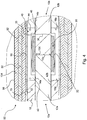
- FIG. 1 shows the structure of a typical mass-impregnated HVDC cable 10.
- Cable 10 is formed of a conductor 12 sized for current transport, and made, for example, of copper or aluminium.
- Conductor 12 is surrounded by an inner semiconducting layer 14 made, for example, of carbon paper tapes.
- Conductor 12 and inner semiconducting layer 14 form together the cable conductive core 13.
- PPL paper/polypropylene laminate
- the viscosity of the impregnating compound is, for this kind of cable, typically of about 900-1500 cSt at 60°C (for example, T2015 Impregnating Compound marketed by H&R ChemPharm Ltd., UK).
- Sheath 20 is a continuous tube having the function of confining the impregnating viscous compound; it also has the function of electrostatically screening the conductor 12.
- Inner polymeric jacket 22, metallic tape reinforcement 24, and outer polymeric jacket 26 are provided for mechanical protection.
- Inner and outer polymeric jacket 22, 26 can be made of polyethylene.
- Cable layers 20, 22, 24, 26 can be collectively referred to as "protecting layers”.
- a jointing zone of each cable end 10a, 10b is prepared by stripping off the layers 14-26 so as to leave an exposed portion of a suitable length of each layer, as will be understood from the further description hereinbelow.
- the cable insulation layer 16 is cut essentially perpendicular to the longitudinal axis X of the cable ends 10a, 10b and stripped off for a predetermined length.
- the cut face 16a of the cable insulation layer 16 may be flat, preferably, or slightly tapered, and will form, at the radially outer position, an angle preferably not greater than 2° with a plane perpendicular to the longitudinal axis X (an angle of about 88° to 92° with the longitudinal axis X).
- the cut can be made with a cutting edge at a distance from the surfaces 10c, 10d of the cable ends 10a, 10b so as to allow the electrical and mechanical connection of the conductors 12a,12b.
- the length of removed cable insulation layer 16 should be as short as possible both to easily take the insulation layer off and, more importantly, to expedite the subsequent jointing steps.
- the length of removed cable insulation layer 16, for each cable end can be 10% greater than the length suitable for performing the connection of the conductors 12a,12b. The tapered, pencil-like removal of insulation layer is avoided.
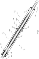
- a metal casing 100 ( Fig. 2 ), formed of two halves, is temporarily slid around both cable ends 10a, 10b, away from the jointing zone.
- conductors 12a, 12b are electrically and mechanically connected at their exposed lengths.
- the connection is preferably accomplished through a conductive connector or ferrule 30.
- Ferrule 30 is a tubular body having, at a longitudinally intermediate position, an internally protruding annular flange 32 so as to form two seats, each for receiving a respective one of the ends of the exposed conductors 12a, 12b abutting onto the flange 32.
- connection of the conductors 12a,12b through the ferrule 30 takes place dispensing with a step of collapsing the ferrule, which would be required to make it have an outer diameter substantially equal to those of the conductors 12a,12b.
- Conductors 12a,12b can also be welded to each other, e.g. through an arc welding process, without any ferrule, and again without the need of a subsequent collapsing step.
- Metal insert 40 is inserted between the opposed cut faces 16a,16b of insulation 16.
- Metal insert 40 can be composed of two semitubular halves each having, at the longitudinal ends, internally protruding annular flanges 42. The two halves are suitably joined together, for example with a pin-and-hole connection at 44.
- Metal insert 40 may be arranged around the ferrule 30 to encase it, leaving an air gap 46 all around ferrule 30. Gap 46 may also be filled with an insulator, e.g. the viscous compound used for impregnating the insulation layer 16.
- an insulator e.g. the viscous compound used for impregnating the insulation layer 16.
- An example of viscous compound suitable for the present invention is T2015 Impregnating Compound (H&R ChemPharm Ltd., UK).
- Metal insert 40 abuts with its flanges 42 onto the inner semiconducting layer 14a,14b, which extends into the gap 46.
- the exposed conductors 12a,12b also extend into the air gap 46.
- Metal insert 40 is suitably electrically connected with the conductors 12a,12b by a metal link 36, e.g. a metal thread inserted in a hole 35 and optionally wound around one of the conductors 12a, 12b.
- a metal link 36 e.g. a metal thread inserted in a hole 35 and optionally wound around one of the conductors 12a, 12b.
- the outer diameter of metal insert 40 is substantially the same as the outer diameter of insulation layers 16 of the cable ends 10a, 10b.
- each flange 42 may be in contact with the cut face 16a of the cable insulation layer 16 or may leave a small air gap in between.
- the longitudinally outer face 42b of each flange 42 may be perpendicular to the longitudinal axis X of symmetry of metal insert 40, or may be depart from being perpendicular in much the same manner as disclosed above in connection with the cut of the insulation layer 16.
- the jointing zone of cable ends 10a, 10b is prepared so that the cable insulation layer 16 is removed for a length essentially equal to half the length of the metal insert 40, and the exposed portion of conductor 12 of each cable end 10a 10b has a length slightly longer (for example 10% longer) than half the length of ferrule 30 but shorter than half the inner length of metal insert 40.
- Metal insert 40 can be made of the same conductive material as conductors 12a, 12b, e.g. copper or aluminium. In view of the above disclosed geometry and feature (metal link 36), metal insert 40 is at the same electric voltage as conductor 12 and inner semiconducting layer 14.
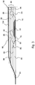
- a layer 50 of semiconducting paper is then formed around the metal insert 40 and the nearby terminal portion of exposed cable insulation layer 16.
- This intermediate semiconducting layer 50 is formed, for example, by winding several turns of a sheet of carbon paper having the shape of an isosceles trapezium, wherein the slant of the edges of the sheet is so selected, with respect to the outer diameter of the cable insulation layer 16 and of the metal insert 40, that the adjacent turns of semiconducting paper will be increasingly shorter as the diameter of the layer 50 increases.
- intermediate semiconducting layer 50 results to be tapered as shown at 52, with a "tapering degree" of for example, 1:15 thickness to length ratio.
- intermediate semiconducting layer 50 is electrically shielding the electric field gradient.
- the low tapering degree of its edges 52 aids to provide an electric field gradient sustainable by the thickness of a stratified impregnated insulation discussed below with reference to Fig.3 .
- the intermediate semiconducting layer 50 overlaps a portion of 50 mm of each cable insulation layer 16.
- two rolls 60 of impregnated insulating paper are similarly formed from sheets having the shape of a right-angled trapezium, wherein the side adjacent to the intermediate semiconducting layer 50 is the tapered one.
- the slant of the tapered side is such that the longitudinal end 62 of impregnated insulating roll 60 has also a tapering degree of, e.g., 1:15.
- the other longitudinal end 64 of impregnated insulating roll 60, formed from the right angle side of the trapezium, is essentially perpendicular to longitudinal axis X.
- Insulating rolls 60 have the same thickness as the intermediate semiconducting layer 50. Insulating paper rolls 60 are each formed at a short distance from intermediate semiconducting layer 50 onto the exposed surface of the cable insulation layer 16, the distance increasing as the diameter increases due to the tapered shape of rolls 50 and 60. Each space between intermediate semiconducting layer 50 and one insulating paper roll 60 is filled by tightly wrapping an impregnated stretch paper tape 70 for several turns longitudinally offset back and forth, until the outer diameter of rolls 50 and 60 is reached, having thus formed an essentially cylindrical surface with an essentially uniform outer diameter.
- a plurality of superposed insulating layers 80 is then constructed about the cylindrical surface formed by intermediate semiconducting layer 50, insulating paper rolls 60 and stretch paper wrappings 70.
- sheets of impregnated insulating paper are used forming more than one layer of rolls of paper, each layer comprising one or more rolls.
- the edges of rolls of one layer - for example rolls 84, 82 - are longitudinally offset with respect to the edges of rolls of a radially adjacent layer - for example rolls 94, 92.
- each roll 84, 82, 94, 92, 104 is preferably formed from a sheet having the shape of an isosceles trapezium (rolls 82, 92, 102) or of a right-angled trapezium (rolls 84, 94, 104), and the spaces between rolls of a same layer are filled with stretch paper 86, 96 similarly to wrappings 70.
- each roll 82, 84, 94, 92, 104 can have a tapering degree of at most 1:10, for minimizing the risk of short circuits. Such tapering degree can increase while increasing the distance of the roll from the longitudinal axis of the cable. If, for example, the tapering degree of the intermediate semiconducting layer 50 and of the insulating rolls 60 is of 1:15, the tapering degree of rolls 84 and 82 can be of 1:13, and that of rolls 92,94 can be of 1:12 and so on.
- a layer of the stratified insulation comprises a central roll 82 formed from an isosceles trapezium, longitudinally centred with respect to the underlying intermediate semiconducting layer 50, and two lateral rolls 84, each formed from a right-angled trapezium.
- the spaces between roll 82 and each roll 84 are filled with stretch paper 86, and are preferably offset with respect to stretch paper 70 of the "underlying" layer. This offset construction aids in electrically containing the electric field gradient.
- Another layer laid radially outside of the above-mentioned one comprises a central roll 92 formed from an isosceles trapezium, and two lateral rolls 94, each formed from a right-angled trapezium.
- the spaces between roll 92 and each roll 94 are filled with stretch paper 96, and are offset with respect to stretch paper 86 of the underlying layer.
- Another further layer laid radially outside of just mentioned layer comprises a single roll 104 formed from an isosceles or right-angled trapezium.
- the stratified insulation is composed by the plurality of superposed insulating layers 80 plus the insulating rolls 60 and the impregnated stretch paper tape 70.
- the longitudinally external edges of the stratified insulation are then "shaved" with a suitable cutting edge, so as to form a smooth outer surface having a sigmoid shape that joins the maximum outer diameter of the stratified insulation with the outer diameter of the cable insulation layer 16.
- An external semiconducting layer 98 is then arranged about (and radially outside of) the stratified insulation, and about the nearby portions of exposed original cable insulation layer 16 until longitudinally reaching and being at some extent superimposed to the exposed outer semiconducting layers 18 of the cables.
- the electrical screening function of the outer semiconducting layer 18 is performed by the external semiconducting layer 98.
- Metal casing 100 previously temporarily slid around both cable ends 10a, 10b, away from the jointing zone, is slid at the jointing zone and electrically and mechanically connected to the lead sheaths 20 of each of the cable ends 10a, 10b, thus reconstructing the electrical continuity of lead sheath 20 and grounding.
- Casing 100 forms essentially a hollow, preferably cylindrical, shield, so as to form, once so mechanically connected to the lead sheaths 20, an enclosed space for protecting the stratified insulation and for containing the viscous compound for impregnating the stratified insulation and cable insulation layer 16.
- Metal casing 100 is made of two portions 101a, 101b each having a tubular wall 102a, 102b having an inner diameter larger than the outer diameter of the stratified insulation.
- An annular flange 106 protrudes radially outwards from the tubular wall 102a, 102b of each portion 101a, 101b at the end of engagement with the other portion 101b, 101a.
- annular flange 110 radially protrudes inwards from the tubular wall 102a, 102b, and an annular flange 112 protrudes radially outwards from a tubular sleeve 114.
- the two tubular walls 102a, 102b are first moved away from each other. Each sleeve 114 is then welded to the underlying exposed lead sheath 20. At least one volume compensating device 130 better disclosed below was inserted in connection with one of the two opposite protruding flanges 112 before the sliding of the casing portions over the cable ends to be joined. The two tubular walls 102a, 102b are then slid towards each other, until the longitudinally inner flanges 106 contact each other and each of the longitudinally outer flanges 110 contact the flanges 112 protruding from the sleeves 114.
- Metal casing 100 further comprises a lug 182 for ground connection.
- the radially outward protruding flanges 106 of the two casing portions 101a, 101b are electrically and mechanically connected, such as through bolt and nut connections 108.
- a sealing gasket (not shown) is preferably provided between the flanges 106.
- the contacting flanges 110, 112 are similarly electrically and mechanically connected, such as through bolt and nut connections 116.
- a sealing gasket 118 is preferably provided between the flanges 110, 112, such as in an annular groove 120 of flange 112.
- Casing 100 comprises two plugs 122, 124 preferably placed at diametrically opposed positions; plug 122 and plug 124 protrude outwards from cylindrical surface 102a, 102b.
- a viscous compound preferably the same as that impregnating the original cable insulation layer 16 and the material constituting the stratified insulation, or at least a viscous compound having substantially the same viscosity, is filled under pressure into casing 100 from plug 122 until it spills from the plug 124.
- the above described sealing gaskets avoid leak of the viscous compound.
- casing 100 comprises a volume compensating device 130 to account for the volume changes of the viscous compound as the cable operating temperature changes.
- volume compensating device 130 comprises a two-walled cylindrical bellows 130. More specifically, volume compensating device 130 comprises a first annular disk 132 which is fixed on the longitudinally inner face of flange 112 that protrudes from sleeve 114 on one end of casing 100 (the left end in FIG. 2 ) such as with screws 134, an axially freely moving second annular disk 136, and two concentric bellows shaped walls 138 and 140 longitudinally extending from the first to the second annular disks 132, 136. Walls 138, 140 are preferably made of stainless steel.
- a cylindrical spacer 142 is preferably fixed to moving disk 136 and cantilever projects toward the other disk 132 between the two bellows shaped walls 138, 140, so as to limit the shortest length of bellows 130.
- An abutment annular wall 144 is also preferably provided to similarly limit the maximum length of bellows 130.
- annular wall 144 projects radially outwards from a sleeve 146 fixed to the first annular disk 132 of volume compensating device 130, which sleeve 146 is slid about sleeve 114 of casing 100.
- the stroke of bellows 130 as allowed by spacer 142 and abutment wall 144 is suitably sized so as to maintain the volume within casing 100 and thus the pressure of the viscous compound within the expected ranges.
- the temperature of the viscous compound should be e.g. of 50-100°C to lower its viscosity and to have a compound suitably fluid to be pumped into the space delimited by casing 100.
- the stand-by temperature when cable 10 is not transporting any electrical current, corresponds to the environmental temperature, and can be e.g. as low as 5°C to 10°C or even lower.
- the viscous compound undergoes a volume decrease and could leave some portion of the paper insulation not suitably impregnated, possibly causing subsequent impairment in the insulation performance.
- its pressure should not be allowed to fall below e.g. 3 bar, while a maximum allowed pressure, at the moment of pouring into the metal casing 100, should be e.g. of 15 bar.
- the temperature can reach up to 55°C at the maximum in the case of impregnated paper insulation 16, of about 85°C in the case of impregnated PPL insulation 16.
- the cable layers radially outer with respect to the lead sheath 20, such as inner polymeric jacket 22, metallic tape reinforcement 24, and outer polymeric jacket 26, which have been removed at the joint, are not reconstructed at all according to the invention.
- a suitable heat shrinkable sheath (not shown) may be provided on each side of the casing 100 from the outer polymeric jacket 26 to a position very near the adjacent end of the casing 100, or even a single heat shrinkable sheath extending about the casing 100 itself from the outer polymeric jacket 26 of one cable end 10a to the outer polymeric jacket 26 of the other cable end 10b.
- Table 1 below sets forth preferred ranges of sizes of an exemplary embodiment of cable joint according to the invention. These figures are provided solely as a guide and to allow the improvement with respect to prior art joints to be appreciated. Any adjustment to the figures below in view of the specific cable size and type, as well as in view of the environmental conditions, is within the common knowledge of a skilled person in the light of the above disclosure.
- the dual walled bellows 130 may be replaced by another volume compensating device, e.g. comprising an external circuit, including a reservoir, for the viscous compound.
- another volume compensating device e.g. comprising an external circuit, including a reservoir, for the viscous compound.
- the above disclosed metal casing 100 may also be used, possibly with the volume compensating device 130, when the impregnated insulation layer of the cable is reconstructed according to the prior art.
- the above disclosed technique for insulating the joint which advantageously avoids the pencil-like removal of the original impregnated insulation layer and considerably shortens the length of the joint, may be advantageously used also when the lead alloy sheath 20 and the layers radially outer thereto are reconstructed in a conventional way, without using the metal casing 100.
Landscapes
- Cable Accessories (AREA)
- Processing Of Terminals (AREA)
- Gas Or Oil Filled Cable Accessories (AREA)
Claims (16)
- Procédé de jonction de deux câbles haute tension imprégnés (10, 10a, 10b), comprenant chacun une âme conductrice (13), fabriquée à partir d'un conducteur (12, 12a, 12b) enveloppé dans une couche semi-conductrice interne (14, 14a, 14b), une couche d'isolation de câble (16), imprégnée d'un composé visqueux, radialement extérieure par rapport à l'âme conductrice (13), une couche semi-conductrice externe (18) radialement extérieure par rapport à la couche d'isolation de câble (16) et au moins une couche de protection (20, 22, 24, 26) radialement extérieure par rapport à la couche semi-conductrice externe (18), le procédé comprenant les étapes de :- exposition d'une longueur de ladite couche d'isolation de câble (16) imprégnée de chaque extrémité de câble (10a, 10b) par retrait de l'au moins une couche de protection (20, 22, 24, 26) et de la couche semi-conductrice externe (18),- exposition d'une longueur terminale du conducteur (12, 12a, 12b) de chaque extrémité de câble (10a, 10b) par découpage, avec une coupe essentiellement perpendiculaire à l'axe longitudinal (X) de chaque câble, de l'épaisseur entière d'une partie de ladite couche d'isolation de câble (16) imprégnée et par retrait de la couche semi-conductrice interne (14, 14a, 14b),- raccordement mécanique et électrique (30, 36) desdits conducteurs (12, 12a, 12b),- remplissage de l'espace laissé par la couche d'isolation de câble (16) imprégnée retirée avec une garniture conductrice (40), laissant au plus un entrefer entre la couche d'isolation de câble (16) imprégnée et la garniture conductrice (40),- fourniture d'une couche semi-conductrice intermédiaire (50) pour entourer la garniture conductrice (40) et s'aboutant sur des parties de couches d'isolation de câble (16) adjacentes à la garniture conductrice (40),- application d'une isolation stratifiée (60, 70, 80), imprégnée d'un composé visqueux, chevauchant longitudinalement la longueur exposée de la couche d'isolation de câble (16) imprégnée de chaque extrémité de câble (10a, 10b) et recouvrant la couche semi-conductrice intermédiaire (50),- blindage électrique (98) des conducteurs (12, 12a, 12b), et- confinement étanche (100) du composé visqueux.
- Procédé selon la revendication 1, dans lequel l'étape de remplissage de l'espace laissé par la couche d'isolation de câble (16) imprégnée retirée avec une garniture conductrice (40) comprend l'agencement d'une garniture de métal (40) ayant sensiblement le même diamètre extérieur que le diamètre extérieur de la couche d'isolation de câble (16) imprégnée.
- Procédé selon la revendication 1, dans lequel l'étape d'application d'une isolation stratifiée (60, 70, 80) comprend l'étape de fourniture de rouleaux (60) d'isolation imprégnée des deux côtés de la couche semi-conductrice intermédiaire (50), lesdits rouleaux (60) ayant sensiblement le même diamètre extérieur que ladite couche semi-conductrice intermédiaire (50) de manière à former une surface cylindrique régulière.
- Procédé selon la revendication 3, dans lequel l'étape d'application d'une isolation stratifiée (60, 70, 80) comprend l'étape d'agencement d'au moins une couche supplémentaire (80) de matériau d'isolation imprégné sur les rouleaux (60) d'isolation imprégnée et la couche semi-conductrice intermédiaire (50).
- Procédé selon la revendication 1, comprenant en outre l'étape d'arasage de l'isolation imprégnée stratifiée (60, 70, 80) au niveau des bords longitudinaux pour obtenir une surface régulière ayant un profil sigmoïde.
- Procédé selon la revendication 1, dans lequel l'étape de blindage électrique du joint est réalisée en enveloppant l'isolation stratifiée (60, 70, 80) avec une couche de matériau semi-conducteur (98).
- Procédé selon la revendication 1, comprenant en outre une étape de fourniture d'un dispositif de compensation de volume (130).
- Joint pour l'épissage de deux câbles HT imprégnés (10, 10a, 10b) comprenant des âmes conductrices (13) respectives fabriquées à partir de conducteurs (12, 12a, 12b) enveloppés dans des couches semi-conductrices internes (14, 14a, 14b), des couches d'isolation de câble (16), imprégnées d'un composé visqueux, radialement extérieures par rapport aux âmes conductrices (13), des couches semi-conductrices externes (18) entourant les couches d'isolation de câble (16), et des couches de protection (20, 22, 24, 26) radialement extérieures par rapport aux couches semi-conductrices externes (18), le joint ayant un axe longitudinal (X) et comprenant :- des conducteurs raccordés mécaniquement et électriquement (12, 12a, 12b, 30) ;- des couches d'isolation de câble (16) imprégnées ayant des faces coupées essentiellement perpendiculaires à l'axe longitudinal du joint sur l'épaisseur entière des couches d'isolation de câble (16), et étant plus courtes que les conducteurs (12, 12a, 12b) respectifs ;- une garniture conductrice (40) interposée entre les faces des couches d'isolation de câble (16) imprégnées, laissant au plus un entrefer entre la garniture conductrice (40) et les faces des couches d'isolation de câble (16) imprégnées ;- une couche semi-conductrice intermédiaire (50) entourant la garniture conductrice (40) et s'aboutant sur des parties de couches d'isolation de câble (16) adjacentes à la garniture conductrice (40) ;- une isolation stratifiée (60, 70, 80), imprégnée d'un composé visqueux, chevauchant longitudinalement les couches d'isolation de câble (16) imprégnées et recouvrant la couche semi-conductrice intermédiaire (50) ;- une couche semi-conductrice externe (98) enveloppant l'isolation stratifiée (60, 70, 80) imprégnée et les couches d'isolation de câble (16) imprégnées ;- un boîtier métallique (100) renfermant la couche semi-conductrice externe (98) et s'étendant sur les couches semi-conductrices externes (18) ; et- un composé visqueux contenu dans ledit boîtier métallique (100).
- Joint selon la revendication 8, dans lequel le joint épisse deux câbles haute tension de courant continu (10, 10a, 10b).
- Joint selon la revendication 8, dans lequel la couche semi-conductrice intermédiaire (50) a des bords (52) présentant un degré d'amincissement d'au plus 1/10.
- Joint selon la revendication 8, dans lequel la couche semi-conductrice intermédiaire (50) chevauche des parties de couches d'isolation de câble (16) sur une zone recouvrant l'interface entre ces couches (16) et la garniture conductrice (40).
- Joint selon la revendication 8, dans lequel l'isolation stratifiée (60, 70, 80) imprégnée comprend au moins deux rouleaux (60) de feuille enroulée de matériau d'isolation imprégné.
- Joint selon la revendication 12, dans lequel l'isolation stratifiée (60, 70, 80) imprégnée comprend au moins trois rouleaux (60, 82, 84, 92, 94, 104) de feuille enroulée de matériau d'isolation imprégné, dans lequel les bords d'un rouleau (60, 82, 84, 92, 94, 104) d'une couche de l'isolation stratifiée (60, 70, 80) imprégnée sont longitudinalement décalés par rapport aux bords d'un rouleau (60, 82, 84, 92, 94, 104) d'une couche radialement adjacente.
- Joint selon l'une quelconque des revendications 12 et 13, dans lequel des enroulements de papier étirable (70, 86, 96) sont interposés dans les espaces entre des bords de rouleaux longitudinalement adjacents (50, 60, 82, 84, 92, 94, 104).
- Joint selon la revendication 8, comprenant un dispositif de compensation de volume (130) positionné à l'intérieur du boîtier métallique (100).
- Ligne d'alimentation comprenant au moins un joint selon la revendication 8.
Applications Claiming Priority (1)
| Application Number | Priority Date | Filing Date | Title |
|---|---|---|---|
| PCT/EP2011/000982 WO2012116712A1 (fr) | 2011-03-01 | 2011-03-01 | Junction pour câbles ht isolés par du papier imprégné ou un stratifié de papier-polypropylène (ppl) |
Publications (2)
| Publication Number | Publication Date |
|---|---|
| EP2681820A1 EP2681820A1 (fr) | 2014-01-08 |
| EP2681820B1 true EP2681820B1 (fr) | 2017-09-13 |
Family
ID=44625328
Family Applications (1)
| Application Number | Title | Priority Date | Filing Date |
|---|---|---|---|
| EP11707346.0A Active EP2681820B1 (fr) | 2011-03-01 | 2011-03-01 | Joint de cables ht isolés au papier imprégné ou papier-polypropylène stratifié (ppl) imprégné |
Country Status (12)
| Country | Link |
|---|---|
| US (1) | US9306382B2 (fr) |
| EP (1) | EP2681820B1 (fr) |
| CN (1) | CN103608990B (fr) |
| AU (1) | AU2011360724B2 (fr) |
| BR (1) | BR112013022018B1 (fr) |
| CA (1) | CA2828496C (fr) |
| DK (1) | DK2681820T3 (fr) |
| ES (1) | ES2651944T3 (fr) |
| NO (1) | NO2681820T3 (fr) |
| NZ (1) | NZ614028A (fr) |
| RU (1) | RU2558371C2 (fr) |
| WO (1) | WO2012116712A1 (fr) |
Families Citing this family (11)
| Publication number | Priority date | Publication date | Assignee | Title |
|---|---|---|---|---|
| KR102183193B1 (ko) | 2014-02-25 | 2020-11-26 | 엘에스전선 주식회사 | 종단접속부를 구비한 전력케이블 |
| KR102258894B1 (ko) * | 2014-08-19 | 2021-06-01 | 엘에스전선 주식회사 | 고점도 절연유 함침 케이블의 중간접속함 |
| EP3128630B1 (fr) * | 2015-08-04 | 2024-02-21 | Nexans | Procédé pour la séparation électrique de la gaine métallique d'un câble mi hvdc |
| DE102018116416A1 (de) * | 2018-07-06 | 2020-01-09 | Nkt Gmbh & Co. Kg | Verbindungsmuffe |
| RU188619U1 (ru) * | 2018-10-25 | 2019-04-18 | Приватное акционерное общество "Украинский научно-исследовательский институт кабельной промышленности" | Секция электрическая кабельная |
| EP3647796B1 (fr) * | 2018-10-30 | 2023-06-07 | Prysmian S.p.A. | Raccord de câble rétrécissable et capteur de tension |
| US20240047956A1 (en) * | 2018-11-07 | 2024-02-08 | Ls Cable & System Ltd. | Jointing system of power cable |
| KR102735373B1 (ko) * | 2018-11-07 | 2024-11-28 | 엘에스전선 주식회사 | 전력케이블의 중간접속 시스템 |
| FR3104873B1 (fr) | 2019-12-16 | 2023-05-26 | Tangram Image Sensor | Terminal communiquant avec imageur perfectionné |
| EP4164075A1 (fr) | 2021-10-06 | 2023-04-12 | Nexans | Raccordements de câbles pour systèmes de câble humides ou semi-humides |
| EP4297209A1 (fr) * | 2022-06-22 | 2023-12-27 | NKT HV Cables AB | Procédé de connexion de conducteurs dans un accessoire de câble préfabriqué |
Family Cites Families (16)
| Publication number | Priority date | Publication date | Assignee | Title |
|---|---|---|---|---|
| US1979150A (en) * | 1931-05-02 | 1934-10-30 | Italiana Pirelli Soc | Feeding joint |
| DE912593C (de) | 1938-07-21 | 1954-05-31 | Siemens Ag | Verfahren zur Isolierung der Verbindungsstellen in OEl- und Massekabelmuffen |
| US3017306A (en) * | 1955-10-13 | 1962-01-16 | Pirelli | Construction of the insulation in joints for high tension electric cables |
| GB916946A (en) | 1959-08-26 | 1963-01-30 | Pirelli | Improvements in or relating to the construction of joints and sealing ends for high-tension electric cables |
| US4051298A (en) * | 1974-05-09 | 1977-09-27 | General Electric Company | Strippable composite of polymeric materials for use in insulated electrical conductors, a method of forming the same and products thereof |
| US4133970A (en) * | 1975-12-30 | 1979-01-09 | Joslyn Mfg. And Supply Co. | Electrical insulation system |
| US4822952A (en) * | 1985-08-21 | 1989-04-18 | Cable Technology Laboratories, Inc. | Electrical cable joint and electrical cable termination and methods of making same |
| JPH04212208A (ja) * | 1990-09-13 | 1992-08-03 | Furukawa Electric Co Ltd:The | ゴム・プラスチック絶縁電力ケーブルとその接続部、ならびに、それらの製造方法 |
| WO1992008265A1 (fr) | 1990-10-25 | 1992-05-14 | Minnesota Mining And Manufacturing Company | Joint de transition pour cables remplis d'huile |
| IL111241A (en) * | 1993-10-18 | 1998-02-22 | Raychem Corp | Closure for high voltage cable connections |
| JP3024627B2 (ja) * | 1998-02-03 | 2000-03-21 | 住友電気工業株式会社 | 海底ソリッドケーブル |
| RU2190913C1 (ru) | 2001-02-07 | 2002-10-10 | Закрытое акционерное общество "АББ Москабель" | Соединительная муфта для силового кабеля с изоляцией из сшитого полиэтилена и способ монтажа муфты |
| FR2911441B1 (fr) * | 2007-01-16 | 2015-08-07 | Prysmian En Cables Et Systemes France | Dispositif de protection pour cable electrique a isolation a base de papier impregne |
| ATE554522T1 (de) | 2008-02-13 | 2012-05-15 | Nexans | Vorrichtung für eine verbindungsstelle zwischen zwei elektrischen hochspannungskabeln mit unterschiedlichen durchmessern |
| EP2197080A1 (fr) * | 2008-12-09 | 2010-06-16 | ABB Research Ltd. | Joint flexible avec materiau résistive de transformation d'un champ électrique pour câbles à courant continu à haute tension et méthode pour la connexion de ces câbles |
| WO2010149229A1 (fr) * | 2009-06-26 | 2010-12-29 | Abb Research Ltd | Câble électrique |
-
2011
- 2011-03-01 RU RU2013143964/07A patent/RU2558371C2/ru active
- 2011-03-01 NO NO11707346A patent/NO2681820T3/no unknown
- 2011-03-01 CN CN201180068775.7A patent/CN103608990B/zh active Active
- 2011-03-01 NZ NZ614028A patent/NZ614028A/en unknown
- 2011-03-01 CA CA2828496A patent/CA2828496C/fr active Active
- 2011-03-01 WO PCT/EP2011/000982 patent/WO2012116712A1/fr not_active Ceased
- 2011-03-01 EP EP11707346.0A patent/EP2681820B1/fr active Active
- 2011-03-01 DK DK11707346.0T patent/DK2681820T3/en active
- 2011-03-01 BR BR112013022018A patent/BR112013022018B1/pt active IP Right Grant
- 2011-03-01 US US14/001,789 patent/US9306382B2/en active Active
- 2011-03-01 ES ES11707346.0T patent/ES2651944T3/es active Active
- 2011-03-01 AU AU2011360724A patent/AU2011360724B2/en active Active
Non-Patent Citations (1)
| Title |
|---|
| None * |
Also Published As
| Publication number | Publication date |
|---|---|
| CN103608990B (zh) | 2017-03-29 |
| RU2558371C2 (ru) | 2015-08-10 |
| US9306382B2 (en) | 2016-04-05 |
| BR112013022018A2 (pt) | 2017-08-01 |
| WO2012116712A1 (fr) | 2012-09-07 |
| CA2828496A1 (fr) | 2012-09-07 |
| AU2011360724A1 (en) | 2013-08-29 |
| CA2828496C (fr) | 2018-01-23 |
| RU2013143964A (ru) | 2015-04-10 |
| AU2011360724B2 (en) | 2016-09-29 |
| BR112013022018B1 (pt) | 2019-12-03 |
| NO2681820T3 (fr) | 2018-02-10 |
| CN103608990A (zh) | 2014-02-26 |
| US20140124263A1 (en) | 2014-05-08 |
| ES2651944T3 (es) | 2018-01-30 |
| DK2681820T3 (en) | 2017-12-11 |
| NZ614028A (en) | 2015-01-30 |
| EP2681820A1 (fr) | 2014-01-08 |
Similar Documents
| Publication | Publication Date | Title |
|---|---|---|
| AU2011360724B2 (en) | Joint for HV cables insulated with impregnated paper or paper-polypropylene laminate (PPL) | |
| JP4139564B2 (ja) | 予め組み立てられた電気スプライスコンポーネント | |
| US20160036213A1 (en) | Cold Shrinkable Termination, Cold Shrinkable Termination Assembly And Method For Manufacturing The Same | |
| US3051770A (en) | Normal joint for high tension cables and process of making the same | |
| US20170222423A1 (en) | Covering processing tool and covering processing method | |
| US11476598B2 (en) | Partly pre-assembled cable joint | |
| JP6802084B2 (ja) | 超電導ケーブルの接続構造、及び超電導ケーブル用接続部材 | |
| EP3186474A1 (fr) | Système et procédé pour former des terminaisons d'extrémité d'un câble à isolant minéral | |
| CN106856666B (zh) | 高压输电线 | |
| US3539703A (en) | High voltage termination apparatus for high voltage cables and pipetype transmission lines | |
| KR101625812B1 (ko) | 튜브형 절연 디바이스, 고전압 전력 장치 및 절연된 고전압 전력 케이블을 제공하기 위한 방법 | |
| JPS6241535Y2 (fr) | ||
| US1773715A (en) | Joint for cables | |
| US2016004A (en) | Electric cable installation | |
| JP7844782B2 (ja) | ケーブル接続構造、電力ケーブル、およびケーブル接続構造の製造方法 | |
| US1905691A (en) | Joint for high tension underground cables | |
| RU235284U1 (ru) | Гибридная кабельная муфта для кабелей среднего напряжения | |
| US1819882A (en) | Insulated cable joint | |
| US4453098A (en) | Coupling unit for connection of high-voltage generator winding lead-out and cable | |
| JP2026084306A (ja) | ケーブル接続構造、連結電力ケーブル、およびケーブル接続構造の製造方法 | |
| JPS6320085B2 (fr) | ||
| US1760546A (en) | Insulating joint for cable sheaths | |
| JP2025088918A (ja) | ケーブル接続構造、連結電力ケーブル、およびケーブル接続構造の製造方法 | |
| EP2954603B1 (fr) | Dispositif d'isolation tubulaire, agencement d'alimentation à haute tension et procédé permettant de fournir un câble d'alimentation haute tension isolé | |
| JP5496592B2 (ja) | 地中ケーブル接続部保護管 |
Legal Events
| Date | Code | Title | Description |
|---|---|---|---|
| PUAI | Public reference made under article 153(3) epc to a published international application that has entered the european phase |
Free format text: ORIGINAL CODE: 0009012 |
|
| 17P | Request for examination filed |
Effective date: 20130828 |
|
| AK | Designated contracting states |
Kind code of ref document: A1 Designated state(s): AL AT BE BG CH CY CZ DE DK EE ES FI FR GB GR HR HU IE IS IT LI LT LU LV MC MK MT NL NO PL PT RO RS SE SI SK SM TR |
|
| DAX | Request for extension of the european patent (deleted) | ||
| GRAP | Despatch of communication of intention to grant a patent |
Free format text: ORIGINAL CODE: EPIDOSNIGR1 |
|
| INTG | Intention to grant announced |
Effective date: 20170410 |
|
| RAP1 | Party data changed (applicant data changed or rights of an application transferred) |
Owner name: PRYSMIAN S.P.A. |
|
| GRAS | Grant fee paid |
Free format text: ORIGINAL CODE: EPIDOSNIGR3 |
|
| GRAA | (expected) grant |
Free format text: ORIGINAL CODE: 0009210 |
|
| AK | Designated contracting states |
Kind code of ref document: B1 Designated state(s): AL AT BE BG CH CY CZ DE DK EE ES FI FR GB GR HR HU IE IS IT LI LT LU LV MC MK MT NL NO PL PT RO RS SE SI SK SM TR |
|
| REG | Reference to a national code |
Ref country code: GB Ref legal event code: FG4D |
|
| REG | Reference to a national code |
Ref country code: CH Ref legal event code: EP |
|
| REG | Reference to a national code |
Ref country code: IE Ref legal event code: FG4D |
|
| REG | Reference to a national code |
Ref country code: AT Ref legal event code: REF Ref document number: 929010 Country of ref document: AT Kind code of ref document: T Effective date: 20171015 |
|
| REG | Reference to a national code |
Ref country code: DE Ref legal event code: R096 Ref document number: 602011041525 Country of ref document: DE |
|
| REG | Reference to a national code |
Ref country code: DK Ref legal event code: T3 Effective date: 20171207 |
|
| REG | Reference to a national code |
Ref country code: SE Ref legal event code: TRGR |
|
| REG | Reference to a national code |
Ref country code: NL Ref legal event code: FP |
|
| REG | Reference to a national code |
Ref country code: LT Ref legal event code: MG4D |
|
| REG | Reference to a national code |
Ref country code: ES Ref legal event code: FG2A Ref document number: 2651944 Country of ref document: ES Kind code of ref document: T3 Effective date: 20180130 |
|
| PG25 | Lapsed in a contracting state [announced via postgrant information from national office to epo] |
Ref country code: HR Free format text: LAPSE BECAUSE OF FAILURE TO SUBMIT A TRANSLATION OF THE DESCRIPTION OR TO PAY THE FEE WITHIN THE PRESCRIBED TIME-LIMIT Effective date: 20170913 Ref country code: LT Free format text: LAPSE BECAUSE OF FAILURE TO SUBMIT A TRANSLATION OF THE DESCRIPTION OR TO PAY THE FEE WITHIN THE PRESCRIBED TIME-LIMIT Effective date: 20170913 |
|
| REG | Reference to a national code |
Ref country code: AT Ref legal event code: MK05 Ref document number: 929010 Country of ref document: AT Kind code of ref document: T Effective date: 20170913 |
|
| REG | Reference to a national code |
Ref country code: NO Ref legal event code: T2 Effective date: 20170913 |
|
| PG25 | Lapsed in a contracting state [announced via postgrant information from national office to epo] |
Ref country code: RS Free format text: LAPSE BECAUSE OF FAILURE TO SUBMIT A TRANSLATION OF THE DESCRIPTION OR TO PAY THE FEE WITHIN THE PRESCRIBED TIME-LIMIT Effective date: 20170913 Ref country code: BG Free format text: LAPSE BECAUSE OF FAILURE TO SUBMIT A TRANSLATION OF THE DESCRIPTION OR TO PAY THE FEE WITHIN THE PRESCRIBED TIME-LIMIT Effective date: 20171213 Ref country code: LV Free format text: LAPSE BECAUSE OF FAILURE TO SUBMIT A TRANSLATION OF THE DESCRIPTION OR TO PAY THE FEE WITHIN THE PRESCRIBED TIME-LIMIT Effective date: 20170913 Ref country code: GR Free format text: LAPSE BECAUSE OF FAILURE TO SUBMIT A TRANSLATION OF THE DESCRIPTION OR TO PAY THE FEE WITHIN THE PRESCRIBED TIME-LIMIT Effective date: 20171214 |
|
| REG | Reference to a national code |
Ref country code: FR Ref legal event code: PLFP Year of fee payment: 8 |
|
| PG25 | Lapsed in a contracting state [announced via postgrant information from national office to epo] |
Ref country code: CZ Free format text: LAPSE BECAUSE OF FAILURE TO SUBMIT A TRANSLATION OF THE DESCRIPTION OR TO PAY THE FEE WITHIN THE PRESCRIBED TIME-LIMIT Effective date: 20170913 Ref country code: RO Free format text: LAPSE BECAUSE OF FAILURE TO SUBMIT A TRANSLATION OF THE DESCRIPTION OR TO PAY THE FEE WITHIN THE PRESCRIBED TIME-LIMIT Effective date: 20170913 Ref country code: PL Free format text: LAPSE BECAUSE OF FAILURE TO SUBMIT A TRANSLATION OF THE DESCRIPTION OR TO PAY THE FEE WITHIN THE PRESCRIBED TIME-LIMIT Effective date: 20170913 |
|
| PG25 | Lapsed in a contracting state [announced via postgrant information from national office to epo] |
Ref country code: IS Free format text: LAPSE BECAUSE OF FAILURE TO SUBMIT A TRANSLATION OF THE DESCRIPTION OR TO PAY THE FEE WITHIN THE PRESCRIBED TIME-LIMIT Effective date: 20180113 Ref country code: AT Free format text: LAPSE BECAUSE OF FAILURE TO SUBMIT A TRANSLATION OF THE DESCRIPTION OR TO PAY THE FEE WITHIN THE PRESCRIBED TIME-LIMIT Effective date: 20170913 Ref country code: EE Free format text: LAPSE BECAUSE OF FAILURE TO SUBMIT A TRANSLATION OF THE DESCRIPTION OR TO PAY THE FEE WITHIN THE PRESCRIBED TIME-LIMIT Effective date: 20170913 Ref country code: SK Free format text: LAPSE BECAUSE OF FAILURE TO SUBMIT A TRANSLATION OF THE DESCRIPTION OR TO PAY THE FEE WITHIN THE PRESCRIBED TIME-LIMIT Effective date: 20170913 Ref country code: SM Free format text: LAPSE BECAUSE OF FAILURE TO SUBMIT A TRANSLATION OF THE DESCRIPTION OR TO PAY THE FEE WITHIN THE PRESCRIBED TIME-LIMIT Effective date: 20170913 |
|
| REG | Reference to a national code |
Ref country code: DE Ref legal event code: R097 Ref document number: 602011041525 Country of ref document: DE |
|
| PLBE | No opposition filed within time limit |
Free format text: ORIGINAL CODE: 0009261 |
|
| STAA | Information on the status of an ep patent application or granted ep patent |
Free format text: STATUS: NO OPPOSITION FILED WITHIN TIME LIMIT |
|
| 26N | No opposition filed |
Effective date: 20180614 |
|
| REG | Reference to a national code |
Ref country code: CH Ref legal event code: PL |
|
| PG25 | Lapsed in a contracting state [announced via postgrant information from national office to epo] |
Ref country code: SI Free format text: LAPSE BECAUSE OF FAILURE TO SUBMIT A TRANSLATION OF THE DESCRIPTION OR TO PAY THE FEE WITHIN THE PRESCRIBED TIME-LIMIT Effective date: 20170913 Ref country code: MC Free format text: LAPSE BECAUSE OF FAILURE TO SUBMIT A TRANSLATION OF THE DESCRIPTION OR TO PAY THE FEE WITHIN THE PRESCRIBED TIME-LIMIT Effective date: 20170913 |
|
| REG | Reference to a national code |
Ref country code: BE Ref legal event code: MM Effective date: 20180331 |
|
| REG | Reference to a national code |
Ref country code: IE Ref legal event code: MM4A |
|
| PG25 | Lapsed in a contracting state [announced via postgrant information from national office to epo] |
Ref country code: LU Free format text: LAPSE BECAUSE OF NON-PAYMENT OF DUE FEES Effective date: 20180301 |
|
| PG25 | Lapsed in a contracting state [announced via postgrant information from national office to epo] |
Ref country code: IE Free format text: LAPSE BECAUSE OF NON-PAYMENT OF DUE FEES Effective date: 20180301 |
|
| PG25 | Lapsed in a contracting state [announced via postgrant information from national office to epo] |
Ref country code: CH Free format text: LAPSE BECAUSE OF NON-PAYMENT OF DUE FEES Effective date: 20180331 Ref country code: BE Free format text: LAPSE BECAUSE OF NON-PAYMENT OF DUE FEES Effective date: 20180331 Ref country code: LI Free format text: LAPSE BECAUSE OF NON-PAYMENT OF DUE FEES Effective date: 20180331 |
|
| PG25 | Lapsed in a contracting state [announced via postgrant information from national office to epo] |
Ref country code: MT Free format text: LAPSE BECAUSE OF NON-PAYMENT OF DUE FEES Effective date: 20180301 |
|
| PG25 | Lapsed in a contracting state [announced via postgrant information from national office to epo] |
Ref country code: TR Free format text: LAPSE BECAUSE OF FAILURE TO SUBMIT A TRANSLATION OF THE DESCRIPTION OR TO PAY THE FEE WITHIN THE PRESCRIBED TIME-LIMIT Effective date: 20170913 |
|
| PG25 | Lapsed in a contracting state [announced via postgrant information from national office to epo] |
Ref country code: HU Free format text: LAPSE BECAUSE OF FAILURE TO SUBMIT A TRANSLATION OF THE DESCRIPTION OR TO PAY THE FEE WITHIN THE PRESCRIBED TIME-LIMIT; INVALID AB INITIO Effective date: 20110301 Ref country code: PT Free format text: LAPSE BECAUSE OF FAILURE TO SUBMIT A TRANSLATION OF THE DESCRIPTION OR TO PAY THE FEE WITHIN THE PRESCRIBED TIME-LIMIT Effective date: 20170913 |
|
| PG25 | Lapsed in a contracting state [announced via postgrant information from national office to epo] |
Ref country code: CY Free format text: LAPSE BECAUSE OF FAILURE TO SUBMIT A TRANSLATION OF THE DESCRIPTION OR TO PAY THE FEE WITHIN THE PRESCRIBED TIME-LIMIT Effective date: 20170913 Ref country code: MK Free format text: LAPSE BECAUSE OF NON-PAYMENT OF DUE FEES Effective date: 20170913 |
|
| PG25 | Lapsed in a contracting state [announced via postgrant information from national office to epo] |
Ref country code: AL Free format text: LAPSE BECAUSE OF FAILURE TO SUBMIT A TRANSLATION OF THE DESCRIPTION OR TO PAY THE FEE WITHIN THE PRESCRIBED TIME-LIMIT Effective date: 20170913 |
|
| PGFP | Annual fee paid to national office [announced via postgrant information from national office to epo] |
Ref country code: ES Payment date: 20250401 Year of fee payment: 15 |
|
| PGFP | Annual fee paid to national office [announced via postgrant information from national office to epo] |
Ref country code: SE Payment date: 20260327 Year of fee payment: 16 |
|
| PGFP | Annual fee paid to national office [announced via postgrant information from national office to epo] |
Ref country code: GB Payment date: 20260327 Year of fee payment: 16 |
|
| PGFP | Annual fee paid to national office [announced via postgrant information from national office to epo] |
Ref country code: NO Payment date: 20260327 Year of fee payment: 16 Ref country code: DE Payment date: 20260327 Year of fee payment: 16 Ref country code: DK Payment date: 20260325 Year of fee payment: 16 |
|
| PGFP | Annual fee paid to national office [announced via postgrant information from national office to epo] |
Ref country code: FI Payment date: 20260325 Year of fee payment: 16 Ref country code: IT Payment date: 20260319 Year of fee payment: 16 |
|
| PGFP | Annual fee paid to national office [announced via postgrant information from national office to epo] |
Ref country code: NL Payment date: 20260326 Year of fee payment: 16 |
|
| PGFP | Annual fee paid to national office [announced via postgrant information from national office to epo] |
Ref country code: FR Payment date: 20260325 Year of fee payment: 16 |