EP2682200A1 - Dispositif d'application de charge, matrice de moulage-pressage et procédé moulé-pressé - Google Patents
Dispositif d'application de charge, matrice de moulage-pressage et procédé moulé-pressé Download PDFInfo
- Publication number
- EP2682200A1 EP2682200A1 EP12752433.8A EP12752433A EP2682200A1 EP 2682200 A1 EP2682200 A1 EP 2682200A1 EP 12752433 A EP12752433 A EP 12752433A EP 2682200 A1 EP2682200 A1 EP 2682200A1
- Authority
- EP
- European Patent Office
- Prior art keywords
- press
- plate
- load
- coned disc
- applying device
- Prior art date
- Legal status (The legal status is an assumption and is not a legal conclusion. Google has not performed a legal analysis and makes no representation as to the accuracy of the status listed.)
- Granted
Links
Images


Classifications
-
- B—PERFORMING OPERATIONS; TRANSPORTING
- B21—MECHANICAL METAL-WORKING WITHOUT ESSENTIALLY REMOVING MATERIAL; PUNCHING METAL
- B21D—WORKING OR PROCESSING OF SHEET METAL OR METAL TUBES, RODS OR PROFILES WITHOUT ESSENTIALLY REMOVING MATERIAL; PUNCHING METAL
- B21D22/00—Shaping without cutting, by stamping, spinning, or deep-drawing
- B21D22/02—Stamping using rigid devices or tools
-
- B—PERFORMING OPERATIONS; TRANSPORTING
- B21—MECHANICAL METAL-WORKING WITHOUT ESSENTIALLY REMOVING MATERIAL; PUNCHING METAL
- B21D—WORKING OR PROCESSING OF SHEET METAL OR METAL TUBES, RODS OR PROFILES WITHOUT ESSENTIALLY REMOVING MATERIAL; PUNCHING METAL
- B21D24/00—Special deep-drawing arrangements in, or in connection with, presses
- B21D24/02—Die-cushions
-
- B—PERFORMING OPERATIONS; TRANSPORTING
- B21—MECHANICAL METAL-WORKING WITHOUT ESSENTIALLY REMOVING MATERIAL; PUNCHING METAL
- B21D—WORKING OR PROCESSING OF SHEET METAL OR METAL TUBES, RODS OR PROFILES WITHOUT ESSENTIALLY REMOVING MATERIAL; PUNCHING METAL
- B21D22/00—Shaping without cutting, by stamping, spinning, or deep-drawing
- B21D22/20—Deep-drawing
- B21D22/22—Deep-drawing with devices for holding the edge of the blanks
-
- B—PERFORMING OPERATIONS; TRANSPORTING
- B21—MECHANICAL METAL-WORKING WITHOUT ESSENTIALLY REMOVING MATERIAL; PUNCHING METAL
- B21D—WORKING OR PROCESSING OF SHEET METAL OR METAL TUBES, RODS OR PROFILES WITHOUT ESSENTIALLY REMOVING MATERIAL; PUNCHING METAL
- B21D24/00—Special deep-drawing arrangements in, or in connection with, presses
- B21D24/04—Blank holders; Mounting means therefor
- B21D24/06—Mechanically spring-loaded blank holders
-
- B—PERFORMING OPERATIONS; TRANSPORTING
- B21—MECHANICAL METAL-WORKING WITHOUT ESSENTIALLY REMOVING MATERIAL; PUNCHING METAL
- B21D—WORKING OR PROCESSING OF SHEET METAL OR METAL TUBES, RODS OR PROFILES WITHOUT ESSENTIALLY REMOVING MATERIAL; PUNCHING METAL
- B21D24/00—Special deep-drawing arrangements in, or in connection with, presses
- B21D24/10—Devices controlling or operating blank holders independently, or in conjunction with dies
- B21D24/12—Devices controlling or operating blank holders independently, or in conjunction with dies mechanically
-
- F—MECHANICAL ENGINEERING; LIGHTING; HEATING; WEAPONS; BLASTING
- F16—ENGINEERING ELEMENTS AND UNITS; GENERAL MEASURES FOR PRODUCING AND MAINTAINING EFFECTIVE FUNCTIONING OF MACHINES OR INSTALLATIONS; THERMAL INSULATION IN GENERAL
- F16F—SPRINGS; SHOCK-ABSORBERS; MEANS FOR DAMPING VIBRATION
- F16F1/00—Springs
- F16F1/02—Springs made of steel or other material having low internal friction; Wound, torsion, leaf, cup, ring or the like springs, the material of the spring not being relevant
- F16F1/32—Belleville-type springs
Definitions
- the present invention relates to a load-applying device for a press-forming die, and the load-applying device applies a load to a die member which is included in the press-forming die used when a metal plate is press-formed. Moreover, the present invention relates to a press-forming die to which the load-applying device is incorporated, and a press-forming method.
- the load-applying device according to the present invention is disposed in the press-forming die and can simply adjust both of a stroke and an application load.
- Patent Document 1 a technology is suggested in which an elastic body such as a spring is disposed in a die member included in a press-forming die and thus, a blank holding force is increased in the last period of press-forming.
- Patent Document 2 a technology is suggested in which a coned disc spring capable of generating a high load even at a low stroke is provided as the spring disposed in the die member included in the press-forming die and thus, a blank holding force which is increased in the last period of press-forming is higher.
- the use of the coned disc spring is effective.
- the increment of the blank holding force is adjusted with the kind and the laminating number of sheets of the coned disc spring, and an application load to the blank holding die member becomes a desired value.
- the coned disc springs are laminated, the obtained application load can be changed.
- the entire length of the laminated coned disc spring is also changed. Accordingly, adjusting both ofthe stroke and the application load to a desired value is not easy.
- a load-applying device capable of easily adjusting both of the stroke and the application load is preferable.
- the load-applying device which can be disposed in the press-forming die as one set of components, is preferable.
- An object of the present invention is to provide a load-applying device which applies a load to at least one of a plurality of die members included in a press-forming die, can easily adjust both of a stroke and an application load, and can be disposed in the press-forming die.
- the gist of the present invention is as follows.
- a desired combination of a stroke and an application load can be obtained without preparing a plurality of kinds of springs.
- the load-applying device of a press-forming die can be disposed in the press-forming die as one set of components. Accordingly, a desired load can be applied to a place in which a load is required in the entire press-forming die.
- the inventors found that a lamination coned disc spring was inserted between two plates in a state where the spring is slightly compressed, and by using a reaction force generated when the lamination coned disc spring was further compressed, a load could be easily and stably applied to a press-forming die compared to the related art.
- FIGS. 1A to 1C are longitudinal cross-sectional views showing a state where a load-applying device 1 for a press-forming die according to an embodiment of the present invention is applied to a press-forming die 100 for performing drawing.
- FIG. 1A shows a state where a metal plate 105 is placed on the press-forming die 100.
- FIG. 1B shows a state during the drawing of the metal plate 105.
- FIG. 1C shows a state immediately before the drawing of the metal plate 105 is completed.
- the press-forming die 100 includes a plurality of die members, that is, a punch die member 110, a dice die member 120, and a blank holding die member 130.
- the load-applying device I according to the present embodiment is mounted on the punch die member 110.
- the metal plate 105 to be drawn is placed on the blank holding die member 130.
- the dice die member 120 is lowered, and the drawing of the metal plate 105 starts.
- a portion of the load-applying device 1 according to the present embodiment is pushed by the blank holding die member 130 immediately before the drawing is completed.
- a load shown by a white arrow in FIG. 1C is applied to the blank holding die member 130 included in the press-forming die 100.
- a local additional load separate from the drawing load can be applied to the blank holding die member 130 immediately before the drawing is completed.
- the load-applying device 1 according to the present embodiment is used for the application of the additional load.
- a blank holding force can be sufficiently applied to the metal plate 105. As a result, quality of a press-formed part is improved.
- the load-applying device 1 is not limited to the example shown in FIGS. 1A to 1C , and may be also applied to other uses.
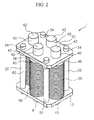
- FIG. 2 is a perspective view showing an example of a schematic configuration of the load-applying device 1 according to the present embodiment.
- FIG. 3 is an exploded view of the load-applying device 1 according to the present embodiment.
- the load-applying device 1 includes a first plate 10, a second plate 20, gap fixing members 30, rods 40, and lamination coned disc springs 60.
- Each of the rods 40 includes a first end 41, a second end 42, and a flange 45.
- the flange 45 is provided between the first end 41 and the second end 42.
- the flange 45 may be integrally formed to the rod 40 by cutting or the like, and a separate flange 45 may be fixed to a rod-shaped member by welding or the like.
- the rods 40 are inserted to center holes 62 of the plurality of coned disc springs from the first ends 41, and thus, the plurality of coned disc springs are laminated, and lamination coned disc springs 60 are configured.
- the first ends 41 of the rods 40 are inserted to first through holes 14 provided in the first plate 10. Moreover, the first plate 10 abuts the lamination coned disc spring 60.
- the second ends 42 of the rods 40 are inserted to second through holes 24 provided in the second plate 20. Moreover, the second plate 20 abuts the flanges 45.
- the lamination coned disc springs 60 are interposed between the first plate 10 and the second plate 20 via the flanges 45. In this state, a biasing force from the lamination coned disc springs 60 is not applied between the first plate 10 and the flange 45.
- the gap fixing members 30 are disposed between the first plate 10 and the second plate 20. Moreover, the first plate 10 and the second plate 20 are fastened in a mutually approaching direction by bolts 33 which are inserted to through holes 32 provided in the gap fixing members 30.
- the first plate 10, the second plate 20, and the lamination coned disc springs 60 are fixed by the gap fixing members 30 via the flanges 45 in a state where the lamination coned disc springs 60 are slightly compressed.
- the gap fixing members 30 are detachably provided between the first plate 10 and the second plate 20 and fix a gap between the first plate 10 and the second plate 20 so as to maintain gaps in which the lamination coned disc springs 60 bias the flanges 45 to the second plate 20.
- the lamination coned disc springs 60 can be compressed between the first plate 10 and the flanges 45 of the rods 40, and thus, a reaction force can be obtained.
- FIG. 4 is an explanation view for easily illustrating positional relationships of the rods 40, flanges 45, and the second plate 20 when the second plate 20 is a semitransparent state in the load-applying device 1 according to the embodiment of the present invention.
- each of the gap fixing members 30 is set to apply the biasing force. That is, the entire length of each of the gap fixing members 30 is set so that the flanges 45 are biased to the second plate 20 by the lamination coned disc springs 60.
- each of the gap fixing members 30 is determined to be (a lamination height in a state where the lamination coned disc spring 60 is not compressed at all) + (a thickness of the flange 45) - (a compressed length ofthe lamination coned disc spring 60 when the flange 45 is biased to the second plate 20 by the lamination coned disc spring 60).
- FIGS. 5A and 5B are a top view and an offset cross-sectional view of the load-applying device 1 according to the present embodiment respectively.
- FIG. 5A is the top view.
- FIG. 5B is the offset cross-sectional view taken along line A-A of FIG. 5A .
- the compressed length of the lamination coned disc spring 60 when flange 45 is biased to the second plate 20 by the lamination coned disc spring 60 is preferably within a range of 5 to 20% with respect to the compressed length when the lamination coned disc spring 60 is completely compressed. If the range is less than 5%, the biasing force is insufficient, and since lamination coned disc springs move mutually, it is not preferable. On other hand, if the range exceeds 20%, when the press-forming ends and the load-applying device 1 according to the present embodiment does not apply the load to the die member, since the lamination coned disc springs 60 apply excessive dynamic loads to the first plate 10 and the second plate 20, and thus, it is not preferable.
- a fixing method is not particularly limited.
- bolts 33 are inserted to through holes 22 provided in the second plate 20 and through holes 32 provided in the gap fixing members 30.
- male screws provided in the bolts 33 are screwed to female screws 12 provided in the first plate 10, and washers 34 provided in the bolts 33 and the second plate 20 are fastened.
- Washers 31 of the gap fixing members 30 are disposed to stably support the first plate 10 and the second plate 20. However, the washers 31 may be omitted.
- one lamination coned disc spring 60 is configured by laminating the coned disc springs.
- the number ofthe laminated coned disc springs is not limited to 36.
- the number of the coned disc springs may be appropriately selected to obtain desired stroke and application load in the entire load-applying device 1 according to the present embodiment.
- a lamination method of the coned disc springs may also be appropriately selected.
- there is a serial lamination method in which all coned disc springs configuring one row of the lamination coned disc springs are arranged in the same posture a parallel-serial lamination method in which some coned disc springs are arranged in reverse postures, or the like.
- a lamination height is increased and a repulsive force (application load) is increased compared to the serial lamination method as the number of the coned disc springs arranged in the reverse posture is increased.
- the load-applying device 1 In the operation of the load-applying device 1, there is a case where the first ends 41 of the rods 40 are pushed and operated and a case where the second ends 42 are pushed and operated.
- the "push" means that first ends 41 or the second ends 42 are moved in the directions in which the laminated coned disc springs 60 are compressed.
- the direction in which each of the lamination coned disc springs 60 is compressed is an axial center direction of the rod 40 which is inserted to the lamination coned disc spring 60.
- the case where the second ends 42 are pushed will be described.
- FIGS. 6A and 6B are cross-sectional views taken along line B-B of FIG. 5A .
- FIG. 6A shows a state where the flanges 45 are biased to the second plate 20.
- FIG. 6B shows a state where the lamination coned disc springs 60 are pushed from the state of FIG. 6A .
- the second ends 42 are pushed by the die member to which the load is to be applied.
- the first plate 10 is mounted on the punch die member 110, and the blank holding die member 130 pushes the second ends 42 of the rods 40.
- the operation of the load-applying device 1 of the present embodiment will be described.
- a state (hereinafter, may be also referred to as a "normal state") in which the flanges 45 are biased to the second plate 20 becomes, that is, the entire length of the lamination coned disc spring 60 becomes L.
- the blank holding die member 130 pushes the second ends 42 of the rods 40 in the direction, in which the lamination coned disc springs 60 are compressed, by a length P from the normal state.
- a reaction force shown by a white arrow of FIG. 6B is generated.
- the reaction force acts on the blank holding die member 130 while the blank holding die member 130 pushes the second ends 42.
- the reaction force acting on the blank holding die member 130 is the application load.
- the length P of FIG. 6B is a stroke.
- the application load per one rod 40 is represented by k x P.
- k is a spring constant of the entire lamination coned disc spring 60 in one rod 40.
- k is the spring constant of the entire of 36 coned disc springs which are laminated.
- FIGS. 7A and 7B are views showing the load-applying device 1 according to the present embodiment when rod length adjustment members 47 detachable to the second ends 42 of the rods 40 are mounted.
- FIGS. 7A and 7B are views showing when the detachable rod length adjustment members 47 are mounted in the cross-sectional view taken along line B-B of FIG. 5A .
- FIG. 7A shows a state where the flanges 45 are biased to the second plate 20.
- FIG. 7B shows a state where the lamination coned disc springs 60 are pushed from the state of FIG. 7A .
- the entire length (hereinafter, referred to as "the entire length in a normal state") of the load-applying device 1 according to the present embodiment in the normal state can be changed by changing the length of L in the normal state.
- a plurality of kinds of gap fixing members 30 having different lengths D (refer to FIG. 5B ) described above may be prepared.
- the plurality of kinds of rod length adjustment members 47 having different thicknesses S and the plurality of kinds of gap fixing members 30 having different lengths D are prepared respectively, and thus, a desired combination of the stroke and the application load can be obtained.
- a detachable first plate thickness adjustment member may be mounted on a surface opposite to the second plate side in the first plate 10.
- a detachable flange thickness adjustment member may be mounted on each of the flanges 45. Also in the flange thickness adjustment member, if a plurality of kinds of flange thickness adjustment members having different thicknesses are prepared, a desired combination of the stroke and the application load can be more easily obtained.
- the load applied to the press-forming die and the stroke can be easily adjusted.
- the number of the rods 30 and the lamination coned disc springs is not limited to four, and may be one or more.
- each of the rod length adjustment members having thicknesses different from one another is detachably mounted on the second end 42 side of each rod, and thus, the load-applying device can be easily applied to even a position corresponding to an inclined surface of the die.
- an end of each of the rod length adjustment member contacting the inclined surface of the die has a hemisphere shape or a shape which comes into surface contact with the inclined surface the die, and thus, the load can be more appropriately applied.
- the first ends 41 of the rods 40 may be pushed by the blank holding die member 130.
- Example is an example of conditions which are adopted for conforming enablement and effects of the present invention, and the present invention is not limited to the example of the conditions.
- the present invention can adopt various conditions as long as the object of the present invention can be achieved without departing from the gist of the present invention.
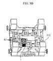
- FIGS. 8A and 8B are views showing an example in which one load-applying device 1 shown in FIG. 4 is disposed in a press-forming die 100A.
- FIG. 8A is an exploded view of the press-forming die 100A
- FIG. 8B is a perspective view when the disposition state of the load-applying device 1 shown in FIG. 4 is viewed from the dice die member 120 side.
- the press-forming die 100A shown in FIG. 8A includes the punch die member 110, the dice die member 120, and the blank holding die member 130. Moreover, the blank holding die member 130 is divided into three divided die members for blank holding 132a, 132b, and 132c.
- one load-applying device 1 is disposed on the punch die member 110 so that, in the last period of the press-forming, a local load is applied only to the divided die member for blank holding 132c among the die members for blank holding 132a, 132b, and 132c divided into three.
- the divided die member for blank holding 132c pushes the second ends 42 of four rods 40 in the last period of the press-forming, the divided die member for blank holding 132c receives the reaction force of the lamination coned disc spring 60, and the application load is applied to the divided die member for blank holding 132c.
- the second ends 42 of the rods 40 are pushed, and thus, the first ends 41 further protrude.
- Concave portions (dashed lines) are provided in the punch die member 110 so that the first ends 41 do not interfere with the punch die member 110 due to the protrusion of the first ends.
- the concave portions are provided, the first plate 10 is fixed to the punch die member 110, and thus, the load-applying device 1 is disposed in the punch die member 110.
- FIGS. 9A and 9B are views showing an example in which four load-applying devices 1 (1a-1, la-2, 1b, 1c) shown in FIG. 4 is disposed in a press-forming die 100B.
- FIG. 9A is an exploded view of the press-forming die 100B.
- FIG. 9B is a perspective view when the disposition state of the load-applying device 1 shown in FIG. 4 is viewed from the dice die member 120 side.
- the press-forming die 100A shown in FIG. 9A and the press-forming die 100B shown in FIG. 8A are the same as each other.
- rod length adjustment members 47 are detachably mounted on the rods 40 of the load-applying device 1 shown in FIG. 4 .
- the load-applying devices 1a-1 and 1a-2 apply the application load to the divided die member for blank holding 132a.
- the load-applying devices 1b applies the application load to the divided die member for blank holding 132b.
- the load-applying devices 1c applies the application load to the divided die member for blank holding 132c.
- the divided die member for blank holding 132a pushes the second ends 42 of eight rods 40 having two load-applying devices 1a-1 and 1a-2 in the last period of the press-forming, the divided die member for blank holding 132a receives the reaction force from the lamination coned disc spring 60, and the application load is applied to the divided die member for blank holding 132a.
- the divided die member for blank holding 132b pushes rod length adjustment members 47 which are mounted on the second ends 42 of four rods 40 included in the load-applying devices 1b in the last period of the press-forming, the divided die member for blank holding 132b receives the reaction force from the lamination coned disc spring 60, and the application load is applied to the divided die member for blank holding 132b.
- the load-applying device 1c is disposed in the punch die member 110.
- the metal plate is press-formed by the press-forming die 100B in which four load-applying devices 1 (1a-1, I a-2, 1b, and 1c) are disposed, lengths D (mm) of the gap fixing members 30, the thicknesses S (mm) of the rod length adjustment members, strokes (mm), and application loads (MPa) are shown in Table 1.
- the thickness S of the rod length adjustment member being 0 mm means a state where the rod length adjustment member 47 is not mounted, that is, the state shown in FIGS. 6A and 6B .
- the load-applying devices 1 were disposed in the press-forming die 100, and as the additional load separate from the press-forming load, the load having the necessary magnitude could be applied to the die member in which a local load application is required in the last period of the press-forming among the plurality of die members included in the press-forming die 100.
- Comparative Examples A to C the steel sheets A to C were formed in the state where the load-applying device was removed in the die structure shown in FIG. 8A , and a hat-shaped cross-sectional member shown in FIG. 10 was press-formed.
- a target value of a distance P was set to 75 mm
- a target value of a distance Q was set to 110 mm.
- the steel sheets A to C was formed using the die structure shown in FIG. 8A , and the hat-shaped cross-sectional member having the shape shown in FIG. 10 was press-formed.
- the steel sheets A to C were formed using the die structure shown in FIG. 9A , and the hat-shaped cross-sectional member having the shape shown in FIG. 10 was press-formed.
- Example 2A Steel Sheet A Four ( FIG. 9A ) 75.8 112.5
- Example 2B Steel Sheet B Four ( FIG. 9A ) 77.8 113.6
- Example 2C Steel Sheet C Four ( FIG. 9A ) 79.4 116.3
- both of the stroke and the application load can be easily adjusted. Accordingly, the load-applying device for a press-forming die is disposed at an appropriate position of the press-forming die, values of both of the stroke and the application load are combined to desired values, the local load is applied to a specific die member included in the press-forming die, and quality of the press-formed part can be improved. Therefore, the present invention has high industrial values.
Landscapes
- Engineering & Computer Science (AREA)
- Mechanical Engineering (AREA)
- Shaping Metal By Deep-Drawing, Or The Like (AREA)
Applications Claiming Priority (2)
| Application Number | Priority Date | Filing Date | Title |
|---|---|---|---|
| JP2011042770 | 2011-02-28 | ||
| PCT/JP2012/054582 WO2012117967A1 (fr) | 2011-02-28 | 2012-02-24 | Dispositif d'application de charge, matrice de moulage-pressage et procédé moulé-pressé |
Publications (3)
| Publication Number | Publication Date |
|---|---|
| EP2682200A1 true EP2682200A1 (fr) | 2014-01-08 |
| EP2682200A4 EP2682200A4 (fr) | 2017-02-01 |
| EP2682200B1 EP2682200B1 (fr) | 2021-07-21 |
Family
ID=46757904
Family Applications (1)
| Application Number | Title | Priority Date | Filing Date |
|---|---|---|---|
| EP12752433.8A Active EP2682200B1 (fr) | 2011-02-28 | 2012-02-24 | Dispositif d'application de charge, matrice de moulage-pressage et procédé moulé-pressé |
Country Status (6)
| Country | Link |
|---|---|
| US (1) | US9481021B2 (fr) |
| EP (1) | EP2682200B1 (fr) |
| JP (1) | JP5866336B2 (fr) |
| CN (1) | CN103402667A (fr) |
| CA (1) | CA2828189C (fr) |
| WO (1) | WO2012117967A1 (fr) |
Families Citing this family (4)
| Publication number | Priority date | Publication date | Assignee | Title |
|---|---|---|---|---|
| US20140137624A1 (en) * | 2012-08-15 | 2014-05-22 | Kenneth L. Smedberg | Die cushion system and method |
| CN106111814B (zh) * | 2016-08-09 | 2019-02-01 | 机械科学研究总院 | 拉延模具 |
| WO2021201038A1 (fr) * | 2020-03-30 | 2021-10-07 | Tdk株式会社 | Appareil de maintien d'outil de poinçonnage, appareil de positionnement d'outil de poinçonnage, appareil de transfert de multi-composant et procédé de fabrication de réseau d'éléments |
| CN114472651A (zh) * | 2022-02-11 | 2022-05-13 | 杭州宇乘五金科技有限公司 | 一种具有分拣功能的碟簧强压模具 |
Family Cites Families (18)
| Publication number | Priority date | Publication date | Assignee | Title |
|---|---|---|---|---|
| US1827440A (en) * | 1929-01-30 | 1931-10-13 | Marquette Tool & Mfg Co | Spring cushion for presses |
| US2084456A (en) * | 1935-01-07 | 1937-06-22 | Fredrich J Rode | Bolster pin holder |
| US2387266A (en) * | 1941-11-17 | 1945-10-23 | Holland Co | Vehicle suspension |
| US2708110A (en) * | 1953-09-25 | 1955-05-10 | Murray G Clay | Belleville variety compression springs |
| US2821380A (en) * | 1953-10-28 | 1958-01-28 | Alco Products Inc | Spring group |
| US3942354A (en) * | 1974-11-14 | 1976-03-09 | Dayton Progress Corporation | Die unit with quick change features |
| JPS6471530A (en) | 1987-09-09 | 1989-03-16 | Kobe Steel Ltd | Fluid pressure molding processing equipment |
| JPH0715610Y2 (ja) | 1989-02-08 | 1995-04-12 | 三住商事株式会社 | プレス加工装置における皺押え台支持機構 |
| JPH03207531A (ja) | 1990-01-08 | 1991-09-10 | Miyama Kogyo Kk | 金属絞り加工装置 |
| JPH10305332A (ja) | 1996-08-23 | 1998-11-17 | Isao Takatsuka | 複数のバネをセットした圧力ユニット |
| ES2146518B1 (es) * | 1997-07-15 | 2001-02-16 | Muller Carranza Luis | Mejoras introducidas en las guias para columnas de muelles de discos conicos superpuestos. |
| JP3772965B2 (ja) | 2001-04-27 | 2006-05-10 | トヨタ自動車株式会社 | プレス金型およびプレス加工方法 |
| US7243521B2 (en) * | 2002-11-14 | 2007-07-17 | Komatsu Ltd. | Cushion pin, wear plate, load supporting device, die cushion, press machine and pressing method |
| JP2004237347A (ja) | 2003-02-07 | 2004-08-26 | Saidaiji Sangyo Kk | プレス成形方法及びプレス成形装置 |
| JP2004344925A (ja) | 2003-05-22 | 2004-12-09 | Nippon Steel Corp | プレス成形金型装置およびプレス成形方法 |
| US7854425B2 (en) * | 2005-12-21 | 2010-12-21 | Halliburton Energy Services, Inc. | Belleville spring guide system |
| JP4771177B2 (ja) | 2008-02-22 | 2011-09-14 | 財団法人北九州産業学術推進機構 | 絞り加工におけるダイナミック制御可能なしわ押さえ機構 |
| CN201279549Y (zh) | 2008-10-06 | 2009-07-29 | 广州普什精密模具有限公司 | 用于汽车座椅后座盆冲压件双浮动拉延的模具 |
-
2012
- 2012-02-24 JP JP2013502290A patent/JP5866336B2/ja active Active
- 2012-02-24 CN CN2012800104692A patent/CN103402667A/zh active Pending
- 2012-02-24 CA CA2828189A patent/CA2828189C/fr active Active
- 2012-02-24 US US14/001,343 patent/US9481021B2/en active Active
- 2012-02-24 WO PCT/JP2012/054582 patent/WO2012117967A1/fr not_active Ceased
- 2012-02-24 EP EP12752433.8A patent/EP2682200B1/fr active Active
Non-Patent Citations (1)
| Title |
|---|
| See references of WO2012117967A1 * |
Also Published As
| Publication number | Publication date |
|---|---|
| JP5866336B2 (ja) | 2016-02-17 |
| US9481021B2 (en) | 2016-11-01 |
| US20130327115A1 (en) | 2013-12-12 |
| CA2828189A1 (fr) | 2012-09-07 |
| JPWO2012117967A1 (ja) | 2014-07-07 |
| CA2828189C (fr) | 2016-09-06 |
| WO2012117967A1 (fr) | 2012-09-07 |
| EP2682200A4 (fr) | 2017-02-01 |
| CN103402667A (zh) | 2013-11-20 |
| EP2682200B1 (fr) | 2021-07-21 |
Similar Documents
| Publication | Publication Date | Title |
|---|---|---|
| EP2682200A1 (fr) | Dispositif d'application de charge, matrice de moulage-pressage et procédé moulé-pressé | |
| EP3213833B1 (fr) | Dispositif comprenant une presse, un outil et un système de protection d'outil destiné à travailler des pièces en tôle | |
| US12202026B2 (en) | Press brake | |
| US20180369893A1 (en) | Wedge drive | |
| KR101855884B1 (ko) | 캠 유니트를 이용한 펀칭장치 및 이를 이용한 펀칭방법 | |
| US20150258702A1 (en) | Auxiliary plate for sheet-member processing device and sheet-member processing device using the same | |
| US20100229619A1 (en) | Press brake for bending sheets | |
| US10773293B2 (en) | Hydraulic punch device | |
| US8245557B2 (en) | Press brake for bending sheets | |
| MX2021008959A (es) | Metodo de formacion por prensado y aparato de prensado. | |
| CN112338050A (zh) | 一种铜排冲孔模具的使用方法 | |
| CN213999723U (zh) | 一种钢丝皮带冲孔装置 | |
| CN111069434B (zh) | 冲压模具及其工作方法 | |
| US11565302B2 (en) | Press working apparatus, and setting method and maintenance method thereof | |
| CN213052279U (zh) | 一种铝合金钣金件的冲压成型装置 | |
| WO2001034319A1 (fr) | Presse d'emboutissage et procede d'emboutissage de pieces en tole | |
| US7269893B2 (en) | Tool for piercing nut | |
| CN217748907U (zh) | 高精度冲孔机 | |
| CN220717487U (zh) | 上模结构及新能源汽车零件的冲压模具 | |
| US12076776B2 (en) | Press brake and method of operating press brake | |
| KR900000136B1 (ko) | 범용프레스로서 화인브랭킹 하는 방법과 그 장치 | |
| KR20190000885U (ko) | 바이스 증강장치의 가압스프링 | |
| JP6879607B1 (ja) | 転造加工装置 | |
| EP1449598A1 (fr) | Tablier porte-outil supplémentaire pour compenser la flexion du tablier supérieur ou inférieur d'une presse plieuse | |
| CN209318540U (zh) | 侧冲模具 |
Legal Events
| Date | Code | Title | Description |
|---|---|---|---|
| PUAI | Public reference made under article 153(3) epc to a published international application that has entered the european phase |
Free format text: ORIGINAL CODE: 0009012 |
|
| 17P | Request for examination filed |
Effective date: 20130926 |
|
| AK | Designated contracting states |
Kind code of ref document: A1 Designated state(s): AL AT BE BG CH CY CZ DE DK EE ES FI FR GB GR HR HU IE IS IT LI LT LU LV MC MK MT NL NO PL PT RO RS SE SI SK SM TR |
|
| DAX | Request for extension of the european patent (deleted) | ||
| RA4 | Supplementary search report drawn up and despatched (corrected) |
Effective date: 20170105 |
|
| RIC1 | Information provided on ipc code assigned before grant |
Ipc: B21D 24/12 20060101AFI20161223BHEP Ipc: B21D 24/02 20060101ALI20161223BHEP |
|
| STAA | Information on the status of an ep patent application or granted ep patent |
Free format text: STATUS: EXAMINATION IS IN PROGRESS |
|
| 17Q | First examination report despatched |
Effective date: 20181120 |
|
| RAP1 | Party data changed (applicant data changed or rights of an application transferred) |
Owner name: NIPPON STEEL CORPORATION Owner name: H-ONE CO., LTD. |
|
| GRAP | Despatch of communication of intention to grant a patent |
Free format text: ORIGINAL CODE: EPIDOSNIGR1 |
|
| STAA | Information on the status of an ep patent application or granted ep patent |
Free format text: STATUS: GRANT OF PATENT IS INTENDED |
|
| INTG | Intention to grant announced |
Effective date: 20210211 |
|
| GRAS | Grant fee paid |
Free format text: ORIGINAL CODE: EPIDOSNIGR3 |
|
| GRAA | (expected) grant |
Free format text: ORIGINAL CODE: 0009210 |
|
| STAA | Information on the status of an ep patent application or granted ep patent |
Free format text: STATUS: THE PATENT HAS BEEN GRANTED |
|
| RAP1 | Party data changed (applicant data changed or rights of an application transferred) |
Owner name: H-ONE CO., LTD. |
|
| AK | Designated contracting states |
Kind code of ref document: B1 Designated state(s): AL AT BE BG CH CY CZ DE DK EE ES FI FR GB GR HR HU IE IS IT LI LT LU LV MC MK MT NL NO PL PT RO RS SE SI SK SM TR |
|
| REG | Reference to a national code |
Ref country code: GB Ref legal event code: FG4D |
|
| REG | Reference to a national code |
Ref country code: CH Ref legal event code: EP |
|
| REG | Reference to a national code |
Ref country code: DE Ref legal event code: R096 Ref document number: 602012076156 Country of ref document: DE |
|
| REG | Reference to a national code |
Ref country code: AT Ref legal event code: REF Ref document number: 1412126 Country of ref document: AT Kind code of ref document: T Effective date: 20210815 |
|
| REG | Reference to a national code |
Ref country code: IE Ref legal event code: FG4D |
|
| REG | Reference to a national code |
Ref country code: LT Ref legal event code: MG9D |
|
| REG | Reference to a national code |
Ref country code: NL Ref legal event code: MP Effective date: 20210721 |
|
| REG | Reference to a national code |
Ref country code: AT Ref legal event code: MK05 Ref document number: 1412126 Country of ref document: AT Kind code of ref document: T Effective date: 20210721 |
|
| PG25 | Lapsed in a contracting state [announced via postgrant information from national office to epo] |
Ref country code: FI Free format text: LAPSE BECAUSE OF FAILURE TO SUBMIT A TRANSLATION OF THE DESCRIPTION OR TO PAY THE FEE WITHIN THE PRESCRIBED TIME-LIMIT Effective date: 20210721 Ref country code: ES Free format text: LAPSE BECAUSE OF FAILURE TO SUBMIT A TRANSLATION OF THE DESCRIPTION OR TO PAY THE FEE WITHIN THE PRESCRIBED TIME-LIMIT Effective date: 20210721 Ref country code: NL Free format text: LAPSE BECAUSE OF FAILURE TO SUBMIT A TRANSLATION OF THE DESCRIPTION OR TO PAY THE FEE WITHIN THE PRESCRIBED TIME-LIMIT Effective date: 20210721 Ref country code: NO Free format text: LAPSE BECAUSE OF FAILURE TO SUBMIT A TRANSLATION OF THE DESCRIPTION OR TO PAY THE FEE WITHIN THE PRESCRIBED TIME-LIMIT Effective date: 20211021 Ref country code: PT Free format text: LAPSE BECAUSE OF FAILURE TO SUBMIT A TRANSLATION OF THE DESCRIPTION OR TO PAY THE FEE WITHIN THE PRESCRIBED TIME-LIMIT Effective date: 20211122 Ref country code: RS Free format text: LAPSE BECAUSE OF FAILURE TO SUBMIT A TRANSLATION OF THE DESCRIPTION OR TO PAY THE FEE WITHIN THE PRESCRIBED TIME-LIMIT Effective date: 20210721 Ref country code: LT Free format text: LAPSE BECAUSE OF FAILURE TO SUBMIT A TRANSLATION OF THE DESCRIPTION OR TO PAY THE FEE WITHIN THE PRESCRIBED TIME-LIMIT Effective date: 20210721 Ref country code: BG Free format text: LAPSE BECAUSE OF FAILURE TO SUBMIT A TRANSLATION OF THE DESCRIPTION OR TO PAY THE FEE WITHIN THE PRESCRIBED TIME-LIMIT Effective date: 20211021 Ref country code: AT Free format text: LAPSE BECAUSE OF FAILURE TO SUBMIT A TRANSLATION OF THE DESCRIPTION OR TO PAY THE FEE WITHIN THE PRESCRIBED TIME-LIMIT Effective date: 20210721 Ref country code: SE Free format text: LAPSE BECAUSE OF FAILURE TO SUBMIT A TRANSLATION OF THE DESCRIPTION OR TO PAY THE FEE WITHIN THE PRESCRIBED TIME-LIMIT Effective date: 20210721 Ref country code: HR Free format text: LAPSE BECAUSE OF FAILURE TO SUBMIT A TRANSLATION OF THE DESCRIPTION OR TO PAY THE FEE WITHIN THE PRESCRIBED TIME-LIMIT Effective date: 20210721 |
|
| PG25 | Lapsed in a contracting state [announced via postgrant information from national office to epo] |
Ref country code: PL Free format text: LAPSE BECAUSE OF FAILURE TO SUBMIT A TRANSLATION OF THE DESCRIPTION OR TO PAY THE FEE WITHIN THE PRESCRIBED TIME-LIMIT Effective date: 20210721 Ref country code: LV Free format text: LAPSE BECAUSE OF FAILURE TO SUBMIT A TRANSLATION OF THE DESCRIPTION OR TO PAY THE FEE WITHIN THE PRESCRIBED TIME-LIMIT Effective date: 20210721 Ref country code: GR Free format text: LAPSE BECAUSE OF FAILURE TO SUBMIT A TRANSLATION OF THE DESCRIPTION OR TO PAY THE FEE WITHIN THE PRESCRIBED TIME-LIMIT Effective date: 20211022 |
|
| REG | Reference to a national code |
Ref country code: DE Ref legal event code: R097 Ref document number: 602012076156 Country of ref document: DE |
|
| PG25 | Lapsed in a contracting state [announced via postgrant information from national office to epo] |
Ref country code: DK Free format text: LAPSE BECAUSE OF FAILURE TO SUBMIT A TRANSLATION OF THE DESCRIPTION OR TO PAY THE FEE WITHIN THE PRESCRIBED TIME-LIMIT Effective date: 20210721 |
|
| PLBE | No opposition filed within time limit |
Free format text: ORIGINAL CODE: 0009261 |
|
| STAA | Information on the status of an ep patent application or granted ep patent |
Free format text: STATUS: NO OPPOSITION FILED WITHIN TIME LIMIT |
|
| PG25 | Lapsed in a contracting state [announced via postgrant information from national office to epo] |
Ref country code: SM Free format text: LAPSE BECAUSE OF FAILURE TO SUBMIT A TRANSLATION OF THE DESCRIPTION OR TO PAY THE FEE WITHIN THE PRESCRIBED TIME-LIMIT Effective date: 20210721 Ref country code: SK Free format text: LAPSE BECAUSE OF FAILURE TO SUBMIT A TRANSLATION OF THE DESCRIPTION OR TO PAY THE FEE WITHIN THE PRESCRIBED TIME-LIMIT Effective date: 20210721 Ref country code: RO Free format text: LAPSE BECAUSE OF FAILURE TO SUBMIT A TRANSLATION OF THE DESCRIPTION OR TO PAY THE FEE WITHIN THE PRESCRIBED TIME-LIMIT Effective date: 20210721 Ref country code: EE Free format text: LAPSE BECAUSE OF FAILURE TO SUBMIT A TRANSLATION OF THE DESCRIPTION OR TO PAY THE FEE WITHIN THE PRESCRIBED TIME-LIMIT Effective date: 20210721 Ref country code: CZ Free format text: LAPSE BECAUSE OF FAILURE TO SUBMIT A TRANSLATION OF THE DESCRIPTION OR TO PAY THE FEE WITHIN THE PRESCRIBED TIME-LIMIT Effective date: 20210721 Ref country code: AL Free format text: LAPSE BECAUSE OF FAILURE TO SUBMIT A TRANSLATION OF THE DESCRIPTION OR TO PAY THE FEE WITHIN THE PRESCRIBED TIME-LIMIT Effective date: 20210721 |
|
| 26N | No opposition filed |
Effective date: 20220422 |
|
| PG25 | Lapsed in a contracting state [announced via postgrant information from national office to epo] |
Ref country code: IT Free format text: LAPSE BECAUSE OF FAILURE TO SUBMIT A TRANSLATION OF THE DESCRIPTION OR TO PAY THE FEE WITHIN THE PRESCRIBED TIME-LIMIT Effective date: 20210721 |
|
| REG | Reference to a national code |
Ref country code: DE Ref legal event code: R119 Ref document number: 602012076156 Country of ref document: DE |
|
| PG25 | Lapsed in a contracting state [announced via postgrant information from national office to epo] |
Ref country code: MC Free format text: LAPSE BECAUSE OF FAILURE TO SUBMIT A TRANSLATION OF THE DESCRIPTION OR TO PAY THE FEE WITHIN THE PRESCRIBED TIME-LIMIT Effective date: 20210721 |
|
| REG | Reference to a national code |
Ref country code: CH Ref legal event code: PL |
|
| REG | Reference to a national code |
Ref country code: BE Ref legal event code: MM Effective date: 20220228 |
|
| PG25 | Lapsed in a contracting state [announced via postgrant information from national office to epo] |
Ref country code: LU Free format text: LAPSE BECAUSE OF NON-PAYMENT OF DUE FEES Effective date: 20220224 |
|
| PG25 | Lapsed in a contracting state [announced via postgrant information from national office to epo] |
Ref country code: FR Free format text: LAPSE BECAUSE OF NON-PAYMENT OF DUE FEES Effective date: 20220228 |
|
| PG25 | Lapsed in a contracting state [announced via postgrant information from national office to epo] |
Ref country code: LI Free format text: LAPSE BECAUSE OF NON-PAYMENT OF DUE FEES Effective date: 20220228 Ref country code: IE Free format text: LAPSE BECAUSE OF NON-PAYMENT OF DUE FEES Effective date: 20220224 Ref country code: DE Free format text: LAPSE BECAUSE OF NON-PAYMENT OF DUE FEES Effective date: 20220901 Ref country code: CH Free format text: LAPSE BECAUSE OF NON-PAYMENT OF DUE FEES Effective date: 20220228 |
|
| PG25 | Lapsed in a contracting state [announced via postgrant information from national office to epo] |
Ref country code: BE Free format text: LAPSE BECAUSE OF NON-PAYMENT OF DUE FEES Effective date: 20220228 |
|
| PG25 | Lapsed in a contracting state [announced via postgrant information from national office to epo] |
Ref country code: HU Free format text: LAPSE BECAUSE OF FAILURE TO SUBMIT A TRANSLATION OF THE DESCRIPTION OR TO PAY THE FEE WITHIN THE PRESCRIBED TIME-LIMIT; INVALID AB INITIO Effective date: 20120224 |
|
| PG25 | Lapsed in a contracting state [announced via postgrant information from national office to epo] |
Ref country code: MK Free format text: LAPSE BECAUSE OF FAILURE TO SUBMIT A TRANSLATION OF THE DESCRIPTION OR TO PAY THE FEE WITHIN THE PRESCRIBED TIME-LIMIT Effective date: 20210721 Ref country code: CY Free format text: LAPSE BECAUSE OF FAILURE TO SUBMIT A TRANSLATION OF THE DESCRIPTION OR TO PAY THE FEE WITHIN THE PRESCRIBED TIME-LIMIT Effective date: 20210721 |
|
| PG25 | Lapsed in a contracting state [announced via postgrant information from national office to epo] |
Ref country code: TR Free format text: LAPSE BECAUSE OF FAILURE TO SUBMIT A TRANSLATION OF THE DESCRIPTION OR TO PAY THE FEE WITHIN THE PRESCRIBED TIME-LIMIT Effective date: 20210721 |
|
| PG25 | Lapsed in a contracting state [announced via postgrant information from national office to epo] |
Ref country code: MT Free format text: LAPSE BECAUSE OF FAILURE TO SUBMIT A TRANSLATION OF THE DESCRIPTION OR TO PAY THE FEE WITHIN THE PRESCRIBED TIME-LIMIT Effective date: 20210721 |
|
| PGFP | Annual fee paid to national office [announced via postgrant information from national office to epo] |
Ref country code: GB Payment date: 20260226 Year of fee payment: 15 |