EP2682483A2 - Procédé d'injection de fil métallurgique peu profond et commande de profondeur associée - Google Patents
Procédé d'injection de fil métallurgique peu profond et commande de profondeur associée Download PDFInfo
- Publication number
- EP2682483A2 EP2682483A2 EP13175467.3A EP13175467A EP2682483A2 EP 2682483 A2 EP2682483 A2 EP 2682483A2 EP 13175467 A EP13175467 A EP 13175467A EP 2682483 A2 EP2682483 A2 EP 2682483A2
- Authority
- EP
- European Patent Office
- Prior art keywords
- lance
- outlet
- location data
- metallurgical
- wire
- Prior art date
- Legal status (The legal status is an assumption and is not a legal conclusion. Google has not performed a legal analysis and makes no representation as to the accuracy of the status listed.)
- Withdrawn
Links
Images


Classifications
-
- C—CHEMISTRY; METALLURGY
- C21—METALLURGY OF IRON
- C21B—MANUFACTURE OF IRON OR STEEL
- C21B3/00—General features in the manufacture of pig-iron
- C21B3/02—General features in the manufacture of pig-iron by applying additives, e.g. fluxing agents
-
- C—CHEMISTRY; METALLURGY
- C21—METALLURGY OF IRON
- C21C—PROCESSING OF PIG-IRON, e.g. REFINING, MANUFACTURE OF WROUGHT-IRON OR STEEL; TREATMENT IN MOLTEN STATE OF FERROUS ALLOYS
- C21C5/00—Manufacture of carbon-steel, e.g. plain mild steel, medium carbon steel or cast steel or stainless steel
- C21C5/28—Manufacture of steel in the converter
- C21C5/42—Constructional features of converters
- C21C5/46—Details or accessories
- C21C5/4606—Lances or injectors
- C21C5/4613—Refractory coated lances; Immersion lances
-
- C—CHEMISTRY; METALLURGY
- C21—METALLURGY OF IRON
- C21C—PROCESSING OF PIG-IRON, e.g. REFINING, MANUFACTURE OF WROUGHT-IRON OR STEEL; TREATMENT IN MOLTEN STATE OF FERROUS ALLOYS
- C21C5/00—Manufacture of carbon-steel, e.g. plain mild steel, medium carbon steel or cast steel or stainless steel
- C21C5/28—Manufacture of steel in the converter
- C21C5/42—Constructional features of converters
- C21C5/46—Details or accessories
- C21C5/4606—Lances or injectors
- C21C5/462—Means for handling, e.g. adjusting, changing, coupling
-
- C—CHEMISTRY; METALLURGY
- C21—METALLURGY OF IRON
- C21C—PROCESSING OF PIG-IRON, e.g. REFINING, MANUFACTURE OF WROUGHT-IRON OR STEEL; TREATMENT IN MOLTEN STATE OF FERROUS ALLOYS
- C21C5/00—Manufacture of carbon-steel, e.g. plain mild steel, medium carbon steel or cast steel or stainless steel
- C21C5/28—Manufacture of steel in the converter
- C21C5/42—Constructional features of converters
- C21C5/46—Details or accessories
- C21C5/4673—Measuring and sampling devices
-
- C—CHEMISTRY; METALLURGY
- C21—METALLURGY OF IRON
- C21C—PROCESSING OF PIG-IRON, e.g. REFINING, MANUFACTURE OF WROUGHT-IRON OR STEEL; TREATMENT IN MOLTEN STATE OF FERROUS ALLOYS
- C21C7/00—Treating molten ferrous alloys, e.g. steel, not covered by groups C21C1/00 - C21C5/00
- C21C7/0056—Treating molten ferrous alloys, e.g. steel, not covered by groups C21C1/00 - C21C5/00 using cored wires
-
- F—MECHANICAL ENGINEERING; LIGHTING; HEATING; WEAPONS; BLASTING
- F27—FURNACES; KILNS; OVENS; RETORTS
- F27B—FURNACES, KILNS, OVENS OR RETORTS IN GENERAL; OPEN SINTERING OR LIKE APPARATUS
- F27B3/00—Hearth-type furnaces, e.g. of reverberatory type; Electric arc furnaces ; Tank furnaces
- F27B3/10—Details, accessories or equipment, e.g. dust-collectors, specially adapted for hearth-type furnaces
- F27B3/18—Arrangements of devices for charging
-
- F—MECHANICAL ENGINEERING; LIGHTING; HEATING; WEAPONS; BLASTING
- F27—FURNACES; KILNS; OVENS; RETORTS
- F27D—DETAILS OR ACCESSORIES OF FURNACES, KILNS, OVENS OR RETORTS, IN SO FAR AS THEY ARE OF KINDS OCCURRING IN MORE THAN ONE KIND OF FURNACE
- F27D19/00—Arrangements of controlling devices
-
- F—MECHANICAL ENGINEERING; LIGHTING; HEATING; WEAPONS; BLASTING
- F27—FURNACES; KILNS; OVENS; RETORTS
- F27D—DETAILS OR ACCESSORIES OF FURNACES, KILNS, OVENS OR RETORTS, IN SO FAR AS THEY ARE OF KINDS OCCURRING IN MORE THAN ONE KIND OF FURNACE
- F27D21/00—Arrangement of monitoring devices; Arrangement of safety devices
-
- F—MECHANICAL ENGINEERING; LIGHTING; HEATING; WEAPONS; BLASTING
- F27—FURNACES; KILNS; OVENS; RETORTS
- F27D—DETAILS OR ACCESSORIES OF FURNACES, KILNS, OVENS OR RETORTS, IN SO FAR AS THEY ARE OF KINDS OCCURRING IN MORE THAN ONE KIND OF FURNACE
- F27D19/00—Arrangements of controlling devices
- F27D2019/0028—Regulation
- F27D2019/0071—Regulation using position sensors
-
- F—MECHANICAL ENGINEERING; LIGHTING; HEATING; WEAPONS; BLASTING
- F27—FURNACES; KILNS; OVENS; RETORTS
- F27D—DETAILS OR ACCESSORIES OF FURNACES, KILNS, OVENS OR RETORTS, IN SO FAR AS THEY ARE OF KINDS OCCURRING IN MORE THAN ONE KIND OF FURNACE
- F27D21/00—Arrangement of monitoring devices; Arrangement of safety devices
- F27D21/0035—Devices for monitoring the weight of quantities added to the charge
- F27D2021/0042—Monitoring the level of the solid charge
Definitions
- the present invention relates to a method and system for metal production.
- a ferrous melt is typically produced in a suitable furnace and then tapped into a ladle where it is treated with one or more ingredients for refining or alloying purposes. It is well known to add calcium to the molten ferrous material at this point as a refining agent for oxide inclusion flotation, oxide inclusion morphology modification, desulfurization, etc. Unfortunately, the low density (relative to steel), volatility and reactivity of calcium severely complicate the task of providing a satisfactory process for its addition to the molten material in the ladle.
- calcium has also been added to melts in steelmaking ladles in the form of a calcium metal-containing wire (clad or unclad) continuously fed through the upper surface of the melt.
- wire feeding is that large flows of gas are not needed, as in powder injection, to propel the calcium-containing material into the molten ferrous material.
- the high volatility of calcium hinders the attainment of an efficient utilization of the calcium added in surface wire feeding.
- U.S. Patent No. 4,512,800 discloses an apparatus and method for treating molten ferrous material with processing additives in wire form such as calcium containing wires directly into a quantity of molten material using a heat-resistant lance having an outlet disposable beneath the surface of the molten material.
- wire form such as calcium containing wires directly into a quantity of molten material using a heat-resistant lance having an outlet disposable beneath the surface of the molten material.
- the wire is fed into a passage going through the lance and an inert gas is concurrently injected into the passage together with the wire to prevent clogging of the lance by solidification of molten material while agitating the molten material by gas bubble agitation.
- the present invention is directed to a method and system for dispensing an additive into a molten metal.
- a method comprises positioning an outlet of a lance below a surface of a metallurgical melt, the positioning including determining location data relative to the surface of the metallurgical melt, and dispensing an additive wire out of the outlet while the outlet is below the surface of the metallurgical melt.
- a system comprises a wire feeding apparatus, and a lance configured to receive a metallurgical wire from the wire feeding apparatus and to dispense the metallurgical wire from an outlet of the lance, the lance further configured to dispense the metallurgical wire below a surface of a metallurgical melt.
- the system further comprises a distance measuring device configured to determine location data relative to the surface of a metallurgical melt, and a displacing assembly configured to move the lance in accordance with the location data.
- the metallurgical melt includes a slag layer and a molten metal below the slag layer, and the positioning includes maintaining the outlet below an interface between the slag layer and the molten metal.
- the positioning includes maintaining the outlet at a predetermined depth below the interface based on the determined location data relative to the surface of the metallurgical melt.
- the determining of the location data includes emitting a laser beam toward the surface of the metallurgical melt.
- the determining of the location data is performed by a distance measuring assembly, and the positioning of the outlet of the lance includes sending a signal from the distance measuring assembly to a displacing assembly configured to move the lance.
- the positioning of the outlet of the lance includes moving the lance in response to the signal from the distance measuring assembly.
- the positioning of the outlet of the lance is performed in accordance with information from an encoder configured to track movement of the lance and in accordance with the location data.
- the positioning of the outlet of a lance includes moving the lance together with a wire straightener.
- An encoder is configured to track movement of the lance or movement of a position actuator of the displacing assembly.
- the displacing assembly is configured to move the lance in accordance with information from the encoder and in accordance with the location data.
- the distance measuring device is configured to emit a laser beam.
- the displacing assembly includes an electric motor and a motor control, and the motor control is configured to control the motor in accordance with the location data.
- the displacing assembly includes a hydraulic pump and a hydraulic control, and the hydraulic control is configured to control the hydraulic pump in accordance with the location data.
- the displacing assembly is configured to move the wire feeding apparatus together with the lance in accordance with the location data.
- the wire feeding apparatus includes a wire straightener.
- the displacing assembly is configured to maintain the outlet of the lance at a predetermined depth in the metallurgical melt based on the location data.
- the displacing assembly is configured to maintain the outlet of the lance at the predetermined depth from an interface between a slag layer and a molten metal of the metallurgical melt.
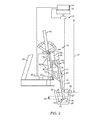
- FIG. 1 a system that includes wire feeding apparatus 10 for shallow metallurgical wire injection, and depth control lance 12 for feeding an additive wire into a quantity of molten metal below the surface of the molten metal.
- Lance 12 comprises inlet 14, outlet 16, and passage 18 provided between inlet 14 and outlet 16 for additive wire 20 being fed through lance 12.
- Wire feeding apparatus 10 includes laser device 22 (also referred to as a distance measuring device).
- Laser device 22 can include a laser emitter 23 or laser range finder.
- Laser device 22 outputs laser beam 24 to scan distance 37 from laser device 22 to top surface 26 of slag layer 27 in metallurgical vessel 30.
- Laser device 22 can have a cooling means 32 for cooling a laser emitter and associated equipment of laser device 22. Any one or a combination of range and position data from laser device 22 is sent to laser scanning unit 34.
- Laser scanning unit 34 can be a laptop computer or personal computer tower. Laser scanning unit 34 is configured to calculate the distance and/or position from top surface 26 of slag layer 27 to laser device 22. Since lance 12 is configured to be displaced along a predetermined path and the position of laser device 22 relative to lance 12 is known via encoder 44, laser scanning unit 34 can send a signal to motor control 35 (also referred to as a controller) to raise or lower lance 12 to desired penetration depth 36 into steel melt 28.
- FIG. 1 shows encoder 44 in communication with motor control 35.
- lance 12 can be performed in accordance with information from encoder 44 and laser device 22.
- lance 12 will penetrate to the same range of predetermined depth 36, for example 12 to 24 inches (30 to 61 cm), into steel melt 28 during the feeding of metallurgical wire 20. It will be appreciated that other numerical values and ranges for predetermined depth 36 may be used.
- tip 46 of lance 12 it is desired to maintain tip 46 of lance 12 at a shallow predetermined depth, 12 to 24 inches for example, in the metal or steel melt 28.
- tip 46 of lance 12 is placed in a position which is 12 to 24 inches (30 to 61 cm) below top 29 of steel melt 28.
- Top 29 of the steel melt 28 is below slag layer 27.
- Top 29 is referred to as interface 29 between slag layer 27 and steel melt 28.
- Slag layer 27 may contain lime, silica, or other material. Slag layer 27 may be added to molten metal 28 in metallurgical vessel 30 prior to dispensing of additive wire 20 into molten metal 28.
- Wire feeding apparatus 10 can have a means for displacing lance 12 along the front of structural member 40 such as motor driven chain 42 operatively coupled to motor 43, as shown in FIG. 1 or a hydraulically driven unit such as a telescoping unit ( FIG. 2 ) which can be driven in the extending and contracting positions.
- structural member 40 such as motor driven chain 42 operatively coupled to motor 43, as shown in FIG. 1 or a hydraulically driven unit such as a telescoping unit ( FIG. 2 ) which can be driven in the extending and contracting positions.
- Motor control 35 is configured to control the operation of motor 43 which displaces lance 12 along a predetermined path.
- Motor 34 is also referred to as a position actuator and can be an electric motor for example.
- Encoder 44 which can be an analog device for example, is configured to track the movement of lance 12 in both movement directions 47 relative to laser device 22 and/or relative to vessel 30. Encoder 44 is configured to sense and keep track of back and forth movements of motor 43 or lance 12.
- wire feeding apparatus 10 includes any one or both of wire straightener 48 and cone 50 to assist in the feeding of metallurgical wire 20 into wire feeding apparatus 10.
- wire feeding apparatus 10 includes proximity switch 52 configured to be activated by sensor 54 when lance 12 is in a particular designated position on wire feeding apparatus 10.
- the position of lance 12 can be driven by motor 43 configured to drive chain 42.
- wire feeding apparatus 10 includes block device 56 to prevent lance 12 from being positioned too far down in metallurgical melt 27, 28.
- Metallurgical melt refers to molten metal 28 and any slag layer 27.
- laser device 22 is mounted on structural support 40 which supports wire feeding apparatus 10.
- Laser device 22 can include moveable cover piece 58 to protect laser optics and any heat-sensitive parts of laser device 22 from heat radiated from metallurgical melt 27, 28.
- Laser device 22 can determine distance 37 of up to 40 meters from laser device 22 to a target, such as top surface 26 of slag layer 27.
- a suitable laser device such as a laser emitter or laser range finder and laser scanning unit, is available from the Ferrotron Division of Minteq International Inc. of Duisburg, Germany.
- FIG. 2 shows another embodiment of the invention in which a system includes wire feeding apparatus 10 for shallow metallurgical wire injection, and depth control lance 12 for feeding additive wire 20 into a quantity of molten metal 28 below the surface of the molten metal surface.
- Lance 12 comprises inlet 14, outlet 16, and passage 18 provided between inlet 14 and outlet 16 for additive wire 20 being fed through lance 12.
- Laser device 22 (also referred to as a distance measuring device) can be a laser emitter or laser range finder.
- Laser device 22 can be mounted at a location in the production facility which has a view of slag layer 27 in metallurgical vessel 30.
- Laser device 22 emits laser beam 24 to scan the position and/or distance from laser device 22 to top surface 26 of slag layer 27 in metallurgical vessel 30.
- the position and/or distance is referred to herein as location data of the laser device 22 relative to top surface 26 of slag layer 27.
- the location data from laser device 22 is sent to laser scanning unit 34 configured to calculate distance 37 from laser device 22 to top surface 26 of slag layer 27.
- Laser scanning unit 34 can be, for example, a laptop computer or personal computer tower. Because lance 12 is displaced along a predetermined path and the location of laser device 22 is known in the coordinate system of lance 12, laser scanning unit 34 can send a signal to hydraulic control 35 to raise or lower lance 12 such that lance tip 46 is at desired depth 36 in steel melt 28 based on distance 37 from laser device 22 to slag layer 27.
- Encoder 44 can provide the location of laser device 22 within the coordinate system of lance 12.
- FIG. 2 shows encoder 44 in communication with hydraulic control 35.
- moving lance 12 in directions 47 can be controlled by hydraulic control 35 in accordance with information from encoder 44 and laser device 22.
- the depth control system which comprises laser device 22, laser scanning unit 34, hydraulic control 35, and encoder 44, can operate as a feedback control loop.
- the position of lance 12 is adjusted automatically by the depth control system to maintain desired depth 36 while the level of interface 29 fluctuates, such as may occur during a change in the amount of molten metal 28 in vessel 30.
- Wire feeding apparatus 10 can have a displacing means for displacing lance 12 along the front of structural member 40.
- the displacing means or displacing assembly includes hydraulic control 35 (also referred to as a controller) configured to control operation of pump 43 (also referred to as a position actuator).
- Pump 43 is configured to extend and contract telescoping hydraulic cylinders 60 which displace lance 12 along a predetermined path.
- Encoder 44 is configured to track the movement of lance 12 in both directions 47 along the predetermined path.
- Encoder 44 can be an analog device.
- tip 46 of lance 12 is placed in a position which is 12 to 24 inches (30 to 61 cm) from interface 29 between steel melt 28 and slag layer 27.
- Wire feeding apparatus 10 can have a wire straightener 48 and/or cone to assist in feeding of metallurgical wire 20 into wire feeding apparatus 10.
- tip 46 of lance 12 at shallow predetermined depth 36 in the metal or steel melt 28, preferably 12 to 24 inches (30 to 61 cm) deep. It will be appreciated that other numerical values and ranges for predetermined depth 36 may be used.
- Wire feeding apparatus 10 can have proximity switch 52 configured to be activated by a sensor on lance 12 when lance 12 is in a particular designated position.
- the position of lance 12 can be driven by telescoping hydraulic cylinders 60 configured to drive carriage 62 on wire feeding apparatus 10 in both the up and down movements 47.
- laser device 22 is mounted on structure 70 in a metallurgical production facility. Lance 12 is movable relative to structure 70. Laser device 22 is configured to determine distance 37 from a target, such as top surface 26 of slag layer 27, to laser device 22. Distance 37 can be in the range of 20 to 40 meters.
- a suitable laser device 22, such as a laser emitter or laser range finder and laser scanning unit, is available from the Ferrotron Division of Minteq International Inc. of Duisburg, Germany.
- carriage 62 can have wheels 72 ( FIG. 2 ) which ride in grooves 74 ( FIG. 3 ).
- Lance fitting 76 can connect lance 12 to wire straightener 48.
- Wire feeding apparatus 10 can have an inert gas which is injected into lance 12 to prevent solidification of steel around lance 12 and assist which mixing of the metallurgical additive from metallurgical wire 20 with the steel or melt.
- Wire straightener 48 can have motor 78 which drives gears in gear box 80.
- lance 12 is made of heat resistant material. Lance 12 is configured to resist degradation and corrosion when exposed to molten metal 28, such as molten steel.
- lance 12 includes a ceramic refractory casing made of alumina or any other refractory material such as those used to cover the interior of kilns and the like.
- metallurgical wire 20 is a calcium-containing wire.
- Examples of calcium-containing wire include a tubular sheath of iron or steel having a central core filled with calcium.
- FIGS. 1 and 2 show a schematic communication line between scanning unit 34 and distance measuring device 22, a schematic communication line between controller 35 and position actuator 43, a schematic communication line between controller 35 and encoder 44, and a schematic communication line between scanning unit 34 and controller 35.
- the schematic connection lines represent any form of communication.
- the communication lines can represent physical wires, or wireless communication, or a combination thereof.
- wire straightener 48 can include a plurality of rollers between which metallurgical wire 20 is passed and straightened in preparation for delivery through passage 18 of lance 12. Rollers may be coupled to the gears in gear box 80 ( FIG. 2 ) which are driven by motor 78. Wire straightener 48 is attached to lance 12. The means for displacing the lance causes lance 12 and wire straightener 48 to move together.
- activation of motor 43 causes chain 42 to raise or lower lance 12 together with wire straightener 48.
- lance 12 and wire straightener 42 are attached to carriage 62 so that activation of pump 43 causes hydraulic cylinders 60 to raise or lower lance 12 together with wire straightener 48. In other embodiments, lance 12 and wire straightener 48 do not move together.
- a displacing assembly comprises position actuator 43 (an electric motor or a hydraulic pump, for example) and controller 35 (a motor control or a hydraulic control, for example).
- a distance measuring assembly comprises distance measuring device 22 (a laser device, for example) and scanning unit 34 (a laser scanning unit, for example). Other types of distance measuring devices are within the scope of the present invention. For example, an acoustic distance measuring device and associated acoustic scanning unit can be used instead of laser device 22 and laser scanning unit 34.
- the displacing assembly of FIG. 1 can be used in combination with the distance measuring assembly of FIG. 2
- the displacing assembly of FIG. 2 can be used in combination with the distance measuring assembly of FIG. 1 .
Landscapes
- Engineering & Computer Science (AREA)
- Chemical & Material Sciences (AREA)
- Materials Engineering (AREA)
- Metallurgy (AREA)
- Organic Chemistry (AREA)
- Manufacturing & Machinery (AREA)
- Mechanical Engineering (AREA)
- General Engineering & Computer Science (AREA)
- Furnace Charging Or Discharging (AREA)
- Treatment Of Steel In Its Molten State (AREA)
- Vertical, Hearth, Or Arc Furnaces (AREA)
- Length Measuring Devices By Optical Means (AREA)
- Waste-Gas Treatment And Other Accessory Devices For Furnaces (AREA)
Applications Claiming Priority (2)
| Application Number | Priority Date | Filing Date | Title |
|---|---|---|---|
| US201261668954P | 2012-07-06 | 2012-07-06 | |
| US13/933,768 US9187791B2 (en) | 2012-07-06 | 2013-07-02 | Shallow metallurgical wire injection method and related depth control |
Publications (2)
| Publication Number | Publication Date |
|---|---|
| EP2682483A2 true EP2682483A2 (fr) | 2014-01-08 |
| EP2682483A3 EP2682483A3 (fr) | 2016-10-12 |
Family
ID=48745828
Family Applications (1)
| Application Number | Title | Priority Date | Filing Date |
|---|---|---|---|
| EP13175467.3A Withdrawn EP2682483A3 (fr) | 2012-07-06 | 2013-07-08 | Procédé d'injection de fil métallurgique peu profond et commande de profondeur associée |
Country Status (4)
| Country | Link |
|---|---|
| US (1) | US9187791B2 (fr) |
| EP (1) | EP2682483A3 (fr) |
| JP (1) | JP2014040658A (fr) |
| ZA (1) | ZA201305068B (fr) |
Cited By (2)
| Publication number | Priority date | Publication date | Assignee | Title |
|---|---|---|---|---|
| WO2017046453A1 (fr) * | 2015-09-15 | 2017-03-23 | Outotec (Finland) Oy | Procédé et agencement permettant de surveiller les caractéristiques d'un processus de four dans un espace de four et unité de surveillance de processus |
| WO2017046451A1 (fr) * | 2015-09-15 | 2017-03-23 | Outotec (Finland) Oy | Procédé et agencement pour le réglage de caractéristiques d'un processus en four dans un espace de four et unité d'injection |
Families Citing this family (1)
| Publication number | Priority date | Publication date | Assignee | Title |
|---|---|---|---|---|
| WO2020118308A1 (fr) * | 2018-12-07 | 2020-06-11 | Mono Ceramics Inc. | Collecteur amélioré pour lance de désulfuration |
Citations (2)
| Publication number | Priority date | Publication date | Assignee | Title |
|---|---|---|---|---|
| DE2745251A1 (de) * | 1977-10-07 | 1979-04-19 | Siemens Ag | Einrichtung zur beruehrungsfreien messung der standhoehe der schmelze bei schmelzprozessen |
| US4512800A (en) | 1983-08-12 | 1985-04-23 | Pfizer Inc. | Wire injection apparatus |
Family Cites Families (11)
| Publication number | Priority date | Publication date | Assignee | Title |
|---|---|---|---|---|
| JPS4984493A (fr) * | 1972-12-18 | 1974-08-14 | ||
| US4481032A (en) * | 1983-08-12 | 1984-11-06 | Pfizer Inc. | Process for adding calcium to a bath of molten ferrous material |
| JPS613822A (ja) * | 1984-06-19 | 1986-01-09 | Nippon Kokan Kk <Nkk> | 溶鋼温度で蒸気圧が高くなる合金元素の溶鋼への添加方法 |
| JPS6447809A (en) * | 1987-08-13 | 1989-02-22 | Sumitomo Metal Ind | Method for raising temperature of molten metal in ladle |
| JPH09164474A (ja) * | 1995-12-13 | 1997-06-24 | Nippon Kokan Pipe Fittings Mfg Co Ltd | 注湯装置の溶湯レベル制御方法 |
| JP4228901B2 (ja) * | 2003-12-08 | 2009-02-25 | 住友金属工業株式会社 | 溶融金属の連続鋳造方法 |
| US8221677B2 (en) * | 2007-04-02 | 2012-07-17 | Specialty Minerals (Michigan) Inc. | Wire injection lance nozzle insert |
| JP4858295B2 (ja) * | 2007-05-09 | 2012-01-18 | 住友金属工業株式会社 | 析出物が微細分散した高強度鋼材および高強度鋼材用鋳片の連続鋳造方法 |
| US7736415B2 (en) * | 2007-09-05 | 2010-06-15 | Specialty Minerals (Michigan) Inc. | Rotary lance |
| WO2010005506A1 (fr) * | 2008-07-10 | 2010-01-14 | Specialty Minerals (Michigan) Inc. | Ensemble buse de lance d’injection de fil |
| JP5878166B2 (ja) * | 2010-04-30 | 2016-03-08 | アゲリス グループ アクチエボラグAgellis Group Ab | 冶金容器内での測定 |
-
2013
- 2013-07-02 US US13/933,768 patent/US9187791B2/en active Active
- 2013-07-05 ZA ZA2013/05068A patent/ZA201305068B/en unknown
- 2013-07-05 JP JP2013141693A patent/JP2014040658A/ja active Pending
- 2013-07-08 EP EP13175467.3A patent/EP2682483A3/fr not_active Withdrawn
Patent Citations (2)
| Publication number | Priority date | Publication date | Assignee | Title |
|---|---|---|---|---|
| DE2745251A1 (de) * | 1977-10-07 | 1979-04-19 | Siemens Ag | Einrichtung zur beruehrungsfreien messung der standhoehe der schmelze bei schmelzprozessen |
| US4512800A (en) | 1983-08-12 | 1985-04-23 | Pfizer Inc. | Wire injection apparatus |
Cited By (8)
| Publication number | Priority date | Publication date | Assignee | Title |
|---|---|---|---|---|
| WO2017046453A1 (fr) * | 2015-09-15 | 2017-03-23 | Outotec (Finland) Oy | Procédé et agencement permettant de surveiller les caractéristiques d'un processus de four dans un espace de four et unité de surveillance de processus |
| WO2017046451A1 (fr) * | 2015-09-15 | 2017-03-23 | Outotec (Finland) Oy | Procédé et agencement pour le réglage de caractéristiques d'un processus en four dans un espace de four et unité d'injection |
| CN107949760A (zh) * | 2015-09-15 | 2018-04-20 | 奥图泰(芬兰)公司 | 用于监测炉空间中的炉工艺的特征的方法和装置以及工艺监测单元 |
| EP3350527B1 (fr) | 2015-09-15 | 2019-06-19 | Outotec (Finland) Oy | Procédé et agencement permettant de surveiller les caractéristiques d'un processus de four dans un espace de four |
| CN107949760B (zh) * | 2015-09-15 | 2019-12-06 | 奥图泰(芬兰)公司 | 用于监测炉空间中的炉工艺的特征的方法和装置以及工艺监测单元 |
| EA034030B1 (ru) * | 2015-09-15 | 2019-12-20 | Оутотек (Финлэнд) Ой | Способ и устройство для регулирования характеристик технологического процесса в печном пространстве печи и инжекционный блок |
| EA035538B1 (ru) * | 2015-09-15 | 2020-07-01 | Оутотек (Финлэнд) Ой | Способ и устройство для контроля характеристик технологического процесса в печном пространстве и блок контроля за ходом технологического процесса |
| US10921061B2 (en) | 2015-09-15 | 2021-02-16 | Outotec (Finland) Oy | Method and arrangement for monitoring characteristics of a furnace process in a furnace space and process monitoring unit |
Also Published As
| Publication number | Publication date |
|---|---|
| US9187791B2 (en) | 2015-11-17 |
| ZA201305068B (en) | 2014-03-26 |
| JP2014040658A (ja) | 2014-03-06 |
| US20140008846A1 (en) | 2014-01-09 |
| EP2682483A3 (fr) | 2016-10-12 |
Similar Documents
| Publication | Publication Date | Title |
|---|---|---|
| KR100741237B1 (ko) | 직접 제련 공정의 압력 제어 방법 | |
| US9187791B2 (en) | Shallow metallurgical wire injection method and related depth control | |
| US7736415B2 (en) | Rotary lance | |
| US3701518A (en) | Oxygen lance control arrangement for basic oxygen furnace | |
| Jiang et al. | Study of plume eye in the copper bottom blown smelting furnace | |
| FI80956C (fi) | Manipulator vid ugnar och liknande. | |
| US4481032A (en) | Process for adding calcium to a bath of molten ferrous material | |
| EP0334915B1 (fr) | Procede pour chauffer de l'acier en fusion contenu dans une poche | |
| DE60131426D1 (de) | Verfahren und vorrichtung zur direkterschmelzung | |
| CN103884400B (zh) | 一种铁水罐铁水深度的测量方法及测量装置 | |
| US20130167688A1 (en) | Method of making low carbon steel using ferrous oxide and mineral carbonates | |
| KR20180132918A (ko) | 용철의 탈황 방법 및 탈황 장치 | |
| KR880000468B1 (ko) | 용융된 철의 욕에 칼슘을 첨가하는 방법 및 그 장치 | |
| US4004919A (en) | Method and apparatus for treating metal | |
| KR101569592B1 (ko) | 전기로 출강구의 탕면 레벨 측정장치 | |
| US4792125A (en) | Consumable lance | |
| US20160313113A1 (en) | Use of a Laser Measuring System and a Pulse Gas Flow to Enable a Feedback Controlled Mold Powder Application | |
| KR20010093053A (ko) | 야금식 용융 용기로부터 금속 용융체를 슬래그 없이배출하기 위한 방법 및 장치 | |
| CN114096686A (zh) | 机械搅拌式脱硫系统 | |
| HU194322B (en) | Steel producing converter | |
| JPH0665625A (ja) | 溶鋼の脱硫方法 | |
| RU97111904A (ru) | Способ выплавки стали в конвертере | |
| RU2315814C2 (ru) | Способ внепечной обработки чугуна | |
| JP2003119524A (ja) | 吹き込み用ランス装置およびこれに用いる位置検出装置 | |
| KW et al. | Fluid slag skimming from steel ladles |
Legal Events
| Date | Code | Title | Description |
|---|---|---|---|
| PUAI | Public reference made under article 153(3) epc to a published international application that has entered the european phase |
Free format text: ORIGINAL CODE: 0009012 |
|
| AK | Designated contracting states |
Kind code of ref document: A2 Designated state(s): AL AT BE BG CH CY CZ DE DK EE ES FI FR GB GR HR HU IE IS IT LI LT LU LV MC MK MT NL NO PL PT RO RS SE SI SK SM TR |
|
| AX | Request for extension of the european patent |
Extension state: BA ME |
|
| PUAL | Search report despatched |
Free format text: ORIGINAL CODE: 0009013 |
|
| AK | Designated contracting states |
Kind code of ref document: A3 Designated state(s): AL AT BE BG CH CY CZ DE DK EE ES FI FR GB GR HR HU IE IS IT LI LT LU LV MC MK MT NL NO PL PT RO RS SE SI SK SM TR |
|
| AX | Request for extension of the european patent |
Extension state: BA ME |
|
| RIC1 | Information provided on ipc code assigned before grant |
Ipc: F27B 3/18 20060101ALI20160902BHEP Ipc: C21C 7/00 20060101ALI20160902BHEP Ipc: C21C 5/46 20060101AFI20160902BHEP Ipc: F27D 21/00 20060101ALI20160902BHEP Ipc: F27D 19/00 20060101ALI20160902BHEP |
|
| STAA | Information on the status of an ep patent application or granted ep patent |
Free format text: STATUS: REQUEST FOR EXAMINATION WAS MADE |
|
| 17P | Request for examination filed |
Effective date: 20170410 |
|
| RBV | Designated contracting states (corrected) |
Designated state(s): AL AT BE BG CH CY CZ DE DK EE ES FI FR GB GR HR HU IE IS IT LI LT LU LV MC MK MT NL NO PL PT RO RS SE SI SK SM TR |
|
| STAA | Information on the status of an ep patent application or granted ep patent |
Free format text: STATUS: EXAMINATION IS IN PROGRESS |
|
| 17Q | First examination report despatched |
Effective date: 20180420 |
|
| STAA | Information on the status of an ep patent application or granted ep patent |
Free format text: STATUS: THE APPLICATION HAS BEEN WITHDRAWN |
|
| 18W | Application withdrawn |
Effective date: 20200210 |