EP2682563A2 - Système de détection résistant aux erreurs pour la détermination d'une relation spatiale entre des composants d'une installation dans des conditions difficiles - Google Patents
Système de détection résistant aux erreurs pour la détermination d'une relation spatiale entre des composants d'une installation dans des conditions difficiles Download PDFInfo
- Publication number
- EP2682563A2 EP2682563A2 EP13175153.9A EP13175153A EP2682563A2 EP 2682563 A2 EP2682563 A2 EP 2682563A2 EP 13175153 A EP13175153 A EP 13175153A EP 2682563 A2 EP2682563 A2 EP 2682563A2
- Authority
- EP
- European Patent Office
- Prior art keywords
- component
- marker
- spatial relationship
- detection device
- electromagnetic radiation
- Prior art date
- Legal status (The legal status is an assumption and is not a legal conclusion. Google has not performed a legal analysis and makes no representation as to the accuracy of the status listed.)
- Withdrawn
Links
- 238000009434 installation Methods 0.000 title claims description 7
- 230000007613 environmental effect Effects 0.000 title 1
- 239000003550 marker Substances 0.000 claims abstract description 155
- 238000001514 detection method Methods 0.000 claims abstract description 69
- 230000005855 radiation Effects 0.000 claims abstract description 57
- 230000005670 electromagnetic radiation Effects 0.000 claims abstract description 47
- 241000196324 Embryophyta Species 0.000 claims description 16
- 238000012545 processing Methods 0.000 claims description 16
- VNWKTOKETHGBQD-UHFFFAOYSA-N methane Chemical compound C VNWKTOKETHGBQD-UHFFFAOYSA-N 0.000 claims description 14
- 238000006073 displacement reaction Methods 0.000 claims description 10
- 239000000463 material Substances 0.000 claims description 10
- 238000004519 manufacturing process Methods 0.000 claims description 7
- 238000000034 method Methods 0.000 claims description 7
- 239000003345 natural gas Substances 0.000 claims description 7
- 239000002803 fossil fuel Substances 0.000 claims description 6
- 241000191291 Abies alba Species 0.000 claims description 5
- 230000006978 adaptation Effects 0.000 claims description 4
- 230000000873 masking effect Effects 0.000 claims description 4
- 239000013598 vector Substances 0.000 claims description 4
- 238000003491 array Methods 0.000 claims description 2
- 238000005259 measurement Methods 0.000 description 7
- 238000010586 diagram Methods 0.000 description 6
- 238000011156 evaluation Methods 0.000 description 6
- 239000003921 oil Substances 0.000 description 6
- 230000003287 optical effect Effects 0.000 description 6
- 238000011109 contamination Methods 0.000 description 5
- 238000005553 drilling Methods 0.000 description 4
- 239000000428 dust Substances 0.000 description 4
- 239000007789 gas Substances 0.000 description 4
- 238000010276 construction Methods 0.000 description 3
- 238000013519 translation Methods 0.000 description 3
- 238000004891 communication Methods 0.000 description 2
- -1 debris Substances 0.000 description 2
- 238000013461 design Methods 0.000 description 2
- 230000006870 function Effects 0.000 description 2
- 239000003209 petroleum derivative Substances 0.000 description 2
- 239000011435 rock Substances 0.000 description 2
- 241000282326 Felis catus Species 0.000 description 1
- 241000361919 Metaphire sieboldi Species 0.000 description 1
- 241000238633 Odonata Species 0.000 description 1
- 238000010521 absorption reaction Methods 0.000 description 1
- 239000012876 carrier material Substances 0.000 description 1
- 238000006243 chemical reaction Methods 0.000 description 1
- 230000008878 coupling Effects 0.000 description 1
- 238000010168 coupling process Methods 0.000 description 1
- 238000005859 coupling reaction Methods 0.000 description 1
- 239000010779 crude oil Substances 0.000 description 1
- 230000001419 dependent effect Effects 0.000 description 1
- 230000005611 electricity Effects 0.000 description 1
- 239000011798 excavation material Substances 0.000 description 1
- 238000002474 experimental method Methods 0.000 description 1
- 238000007667 floating Methods 0.000 description 1
- 230000005484 gravity Effects 0.000 description 1
- 230000003993 interaction Effects 0.000 description 1
- 239000007788 liquid Substances 0.000 description 1
- 238000012423 maintenance Methods 0.000 description 1
- 238000003909 pattern recognition Methods 0.000 description 1
- 230000002093 peripheral effect Effects 0.000 description 1
- 238000003672 processing method Methods 0.000 description 1
- 230000001902 propagating effect Effects 0.000 description 1
- 230000035945 sensitivity Effects 0.000 description 1
- 239000000758 substrate Substances 0.000 description 1
- 239000013589 supplement Substances 0.000 description 1
- 230000001629 suppression Effects 0.000 description 1
- 238000009423 ventilation Methods 0.000 description 1
- XLYOFNOQVPJJNP-UHFFFAOYSA-N water Substances O XLYOFNOQVPJJNP-UHFFFAOYSA-N 0.000 description 1
Images


Classifications
-
- G—PHYSICS
- G01—MEASURING; TESTING
- G01S—RADIO DIRECTION-FINDING; RADIO NAVIGATION; DETERMINING DISTANCE OR VELOCITY BY USE OF RADIO WAVES; LOCATING OR PRESENCE-DETECTING BY USE OF THE REFLECTION OR RERADIATION OF RADIO WAVES; ANALOGOUS ARRANGEMENTS USING OTHER WAVES
- G01S5/00—Position-fixing by co-ordinating two or more direction or position line determinations; Position-fixing by co-ordinating two or more distance determinations
- G01S5/16—Position-fixing by co-ordinating two or more direction or position line determinations; Position-fixing by co-ordinating two or more distance determinations using electromagnetic waves other than radio waves
- G01S5/163—Determination of attitude
-
- E—FIXED CONSTRUCTIONS
- E21—EARTH OR ROCK DRILLING; MINING
- E21D—SHAFTS; TUNNELS; GALLERIES; LARGE UNDERGROUND CHAMBERS
- E21D9/00—Tunnels or galleries, with or without linings; Methods or apparatus for making thereof; Layout of tunnels or galleries
- E21D9/003—Arrangement of measuring or indicating devices for use during driving of tunnels, e.g. for guiding machines
- E21D9/004—Arrangement of measuring or indicating devices for use during driving of tunnels, e.g. for guiding machines using light beams for direction or position control
-
- G—PHYSICS
- G01—MEASURING; TESTING
- G01B—MEASURING LENGTH, THICKNESS OR SIMILAR LINEAR DIMENSIONS; MEASURING ANGLES; MEASURING AREAS; MEASURING IRREGULARITIES OF SURFACES OR CONTOURS
- G01B11/00—Measuring arrangements characterised by the use of optical techniques
- G01B11/26—Measuring arrangements characterised by the use of optical techniques for measuring angles or tapers; for testing the alignment of axes
- G01B11/27—Measuring arrangements characterised by the use of optical techniques for measuring angles or tapers; for testing the alignment of axes for testing the alignment of axes
- G01B11/272—Measuring arrangements characterised by the use of optical techniques for measuring angles or tapers; for testing the alignment of axes for testing the alignment of axes using photoelectric detection means
Definitions
- the invention relates to a sensor arrangement for determining a spatial relationship between a first component and a relatively movable second component of a system and a system with such a sensor arrangement and a method for determining a spatial relationship between a first component and a second component of a system.
- a tunnel boring machine is a machine used to build tunnels.
- Components of a tunnel boring machine are a demounting plate with feeding and bracing devices, equipment for the installation of support and expansion measures, equipment for material removal, a supply unit (electricity, compressed air, ventilation, water), and transport equipment for excavation material, proppant and finishing materials.
- a sensor arrangement for determining a spatial relationship (which may also be called relative orientation, in particular a relative position and / or a relative angular position between the two components) is provided between a first component and a second component of a system, wherein the components movable relative to one another, wherein the sensor arrangement comprises a marker device which is attachable or attached to the first component, a radiation detection device which is attached to the second component and which is arranged by the marker device and / or its immediate vicinity (ie a region directly adjacent to the marker device, which differs from the marker device with respect to the electromagnetic emission properties) to detect emitted (ie reflected or actively emitted) electromagnetic radiation, un d comprises determining means arranged to determine the spatial relationship between the first component and the second component based on the detected electromagnetic radiation and based on previously known geometric data relating to the marker means.
- a system in particular an industrial system
- which has a first component and a second component, wherein the components are movable relative to each other, wherein the system further comprises a sensor arrangement with the features described above for determining a spatial Having relationship between the first component and the second component.
- a method of determining a spatial relationship between a first component and a second component of a plant wherein the components are movable or moved relative to each other (particularly during operation of the plant), wherein a marker means attached to the first component and a radiation detection device is mounted on the second component, wherein in the method with the radiation detection device by the marker device and / or its immediate vicinity emitted electromagnetic radiation is detected, and the spatial relationship between the first component and the second component based on the detected electromagnetic radiation and is determined based on previously known geometric data concerning the marker device.
- component is understood to mean an assembly of a system which is movable in whole or in part relative to another component.
- installation is understood to mean, in particular, a complex technical arrangement comprising a plurality of functionally interacting components, which together fulfill a technical overall task.
- the term "spatial relationship" is understood to mean, in particular, information that is indicative of the distance between different components, whether and which translational displacements exist between different components, and / or whether there is a rotation (for example, an angular offset ) between the components.
- the determination device can thus be set up as a relative orientation a distance between the first component and the second component and / or a translational displacement between the first component and the second component along one or two axes perpendicular to a distance vector between the first component and the second component and / or a twist angle between the first component and the second component.
- the term "marker device” is understood to mean any physical structure whose structural properties of the detection device are known, so that a comparison of these actual properties of the marker device with properties of the marker device on an image permits deriving position and / or rotational information .
- the marker device can be any device that can emit electromagnetic radiation differently than its immediate surroundings, which the radiation detection device can then detect.
- the marker device may be a passive structure reflecting electromagnetic radiation or an active light source, wherein even differences in brightness between the marker device and the environment may already constitute the property of a marker device.
- electromagnetic radiation is understood to mean electromagnetic waves of a suitable wavelength for which the radiation detection device is sensitive.
- both the radiation detection device and the marker device operate in the visible region, i. in the range of wavelengths between 400 nm and 800 nm. According to other embodiments, however, it is also possible to work in the infrared range, in the ultraviolet range or in other frequency ranges.
- geometric data is understood to mean one or more information of a geometric nature concerning the marker device. These may be the shape of an outer contour of the marker device, its area, coordinates of a position of the marker device, distances between different markers of the marker device, etc. These geometric data contain information which is such that on the basis of which the detection device can deduce the spatial relative position between the components from the image of the marker device detected by the radiation detection device.
- a spatial relationship between two components of a plant is detected by non-contact electromagnetic radiation from markers (and / or the direct marker environment) on the first component is detected by a radiation detection device on the second component. If the geometric properties of the marker device are known, then the detection device can reliably determine, on the basis thereof and using the image of the marker device detected by the radiation detection device, how the two components are currently oriented relative to one another, i. rotated and / or spaced. This information can be used as control information for the plant, so that a fault-robust operation can be established.
- cable connections between the components are just as unnecessary as an additional power supply for the component to which the marker device is attached or formed.
- the marker means may include a plurality of marker structures attached to the first component and arranged in three-dimensional space, particularly nonplanar.
- the complete relative pose of the components to each other can be determined from any set of, for example, retroreflective marker structures arranged in three-dimensional space (and not forming a degenerate pattern). It is sufficient to know the constellation of the marker structures or targets so that the necessary parameters of the radiation detection device (for example a camera) are determined can.
- the arrangement of the marker structures on two levels is an example of such a non-planar arrangement which satisfies the above requirements.
- the sensor arrangement may comprise a non-reflective (eg, a dark, in particular black) electromagnetic radiation carrier structure (for example a carrier plate) to which the marker device is arranged (for example, white or retroreflective) electromagnetic radiation reflecting material and which the first component is attachable.
- the sensor arrangement may comprise an electromagnetic radiation-reflecting (for example a white or retroreflective) support structure (for example a support plate) on which the marker device is arranged of non-electromagnetic radiation-reflecting material (for example dark, in particular black) and attachable to the first component.
- the support structure may be formed as exactly one support plate. This leads to a compact arrangement.
- the support structure may be formed as a plurality of interconnected and spaced apart in the spacing direction between the components spatially spaced separate carrier plates.
- the support structure may be formed of retroreflective marker structures mounted in two or more different planes and thus positioned in three-dimensional space. The use of at least two marker levels allows the determination of all six degrees of freedom associated with a relative pose.
- the determination device may be designed to determine the spatial relationship using the detected electromagnetic radiation of only a subset of marker structures of the marker device and based on previously known geometric data concerning only the subset of the marker structures of the marker device.
- only a part of the available marker structures are used to determine the spatial relationship between the two components, whereas another part of the marker structures can be disregarded in an operating state for this purpose.
- the computational effort for determining the spatial relationship between the two components can be minimized, on the other hand, if individual marker structures fail (for example, partial or complete dirt coverage), other redundant marker structures can be used to supplement or alternatively determine the spatial relationship between the components.
- the sensor arrangement according to the invention can also be used under rough conditions, for example in tunnel boring machines, with faultless robustness.
- the support structure may be a plate which differs from the marker device in terms of the reflection and / or absorption properties with respect to electromagnetic radiation. It is only important that between the marker device and the support structure a metrological detectable contrast (with respect to the interaction with electromagnetic radiation).
- the marker device may be designed to be retroreflective.
- a retroreflective marker device is characterized in that it reflects incident electromagnetic radiation preferably or even completely back along the direction of incidence. This increases the accuracy of the marker detection, especially in the presence of dust and dirt.
- plane optical angle reflectors triple mirrors and triple prisms
- reflectors there are rotationally symmetrical lens reflectors (cat's eyes, Lüneburg lenses) as a retroreflective body.
- the marker device may be completely passive.
- a completely passive marker device can be understood to be one which does not itself have to have any active components or has to be activated for operation with, for example, electrical signals or has to be supplied with electrical energy.
- the marker device is a structure made of retroreflective material pieces which are applied to a substrate which is different in terms of optical properties.
- no active light sources, power supply units, processors or the like are required at the marker device. This is particularly advantageous for use of the inventive sensor assembly under harsh conditions, such as in a tunnel boring machine or on an oil rig, where such components may be subject to severe mechanical stress and contamination. Due to the passive design of the marker device this is often arranged in difficult accessible place, low maintenance or even almost maintenance-free.
- a purely passive structure is attached to the first component, which can then be read out without contact from the detection device on the second component.
- This is also advantageous for the following reason: If the two components are operated under harsh conditions such as heavy soiling or heavy mechanical stress, any cable connection between the two components is also problematic and susceptible to failure.
- the sensor arrangement according to the invention functions completely non-contact, so that the entire space between the two components can remain free of any connection means or communication devices.
- the marker device is operated independently of any power supply.
- the marker device may comprise a plurality of separate markers or marker structures whose respective shape, their respective size and their relative position to one another form the previously known geometric data. If a plurality of markers are provided, for example a plurality of circular markers arranged at a distance from each other, then not only the shape and size of a single marker but also the relative position between different markers, in particular a distance, can be used to determine the spatial position between the markers to determine both components. This increases the accuracy of detection.
- the marker means may comprise four preferably circular marker structures, preferably at corners of an imaginary rectangle, more preferably at corners of an imaginary square.
- the marker means may comprise four preferably circular marker structures, preferably at corners of an imaginary rectangle, more preferably at corners of an imaginary square.
- the marker means may comprise seven preferably circular markers. Three of these seven markers may be disposed on a first support plate, and the remaining four markers may be disposed on a second support plate which may be secured to the first support plate and project toward the second component opposite the first support plate.
- the markers of the first carrier plate can be arranged at corners of an imaginary triangle.
- Three markers of the second support plate may be arranged at corners of an imaginary triangle, and the fourth marker may be disposed inside (for example, in the center of gravity) of the triangle.
- the radiation detection device may comprise a camera, which is set up to detect an image containing the marker device.
- a camera may be, for example, a CCD camera or a CMOS camera.
- a sensitivity range of the camera may be tuned to the wavelength of the electronic radiation emitted or reflected by the marker device and / or its immediate surroundings.
- a wavelength-selective (for example, only for optical light-permeable) filter can be arranged in front of the camera.
- the sensor arrangement may comprise an electromagnetic radiation source (in particular a light source) which is designed and arranged for generating electromagnetic radiation (in particular visible light) for illuminating the marker device and / or its immediate surroundings.
- the electromagnetic radiation source can emit electromagnetic radiation in a wavelength range for which the radiation detection device is sensitive.
- the electromagnetic radiation source may be attachable to the second component adjacent to the radiation detection device.
- This geometry can ensure that the light emitted by the radiation source and reflected by the marker device and / or its surroundings and detected by the radiation detection device is at least predominantly the same. In this way, noise can be suppressed.
- the electromagnetic radiation source may comprise a plurality, in particular six, separate electromagnetic emitters, in particular light-emitting diodes or light-emitting diode arrays, which can be directed or directed to the marker device and / or to its immediate surroundings.
- an emission direction of the primary radiation of the emitters can be adjusted so that the primary radiation is directed to the marker device. Due to the provision of multiple emitters, primary radiation may reach the marker device even if an obstacle should occur in the radiation path between an individual emitter and the marker device, as the other emitters may still be free with respect to their radiation path to the marker device.
- the electromagnetic radiators may surround the radiation detection device in an annular manner, in particular concentrically arranged around the radiation detection device.
- a particularly good signal-to-noise ratio can be achieved.
- the electromagnetic radiators may be arranged in a plane plane that is perpendicular to a radiation detection direction of the radiation detection device.
- radiation detection device and the individual radiators can all be arranged close to each other, so that the propagation direction of the Primary electromagnetic radiation from the emitters to the marker device and the secondary electromagnetic radiation from the marker device to the radiation detection device may be substantially the same.
- the electromagnetic radiation source and the radiation detection device may be arranged or aligned such that an emission direction from the electromagnetic radiation source and a detection direction of the radiation detection device are antiparallel to one another. In this way, the space required for propagating electromagnetic radiation to determine the relative orientation between the two components can be kept very small, resulting in a very compact arrangement.
- the determination device can be set up to recognize an image of the marker device on the acquisition data by means of image processing of acquisition data from the radiation detection device and based on the previously known geometric data and to determine indicative information based thereon for the relative orientation between the two components. Due to the contrast between the marker device and its immediate surroundings, an image of the marker device can be determined on the image detected by the radiation detection device using image processing algorithms, for example by pattern recognition or the like. Criteria for determining the position and orientation of the image are the previously known geometric data, with which a sufficiently good or even optimized match is possible. If, for example, it is previously known that the marker device is a circular structure, this can be taken into account in the image processing of the acquisition data as a framework condition to be fulfilled.
- image processing methods can be used in Matthew Harker, Paul O'Leary, "Direct Estimation of Homogeneous Vectors: An Ill-Solved Problem in Computer Vision", by: P. Kalra and S. Peleg (Publisher): ICVGIP 2006, LNCS 4338, pages 919 to 930, 2006 are disclosed.
- the determining means may be arranged to perform the image processing based on a parameter adjustment (i.e., a fit), in particular, a parameter adjustment for minimizing the sum of the smallest squared distances between the detection data and the parameterized known geometric data.
- a parameter adjustment i.e., a fit
- the parameters for adjusting the acquisition data are, for example, the circle radius and the coordinates of the circle center point.
- Such a least squares fit is numerically simple and allows a fault-robust determination of the image of the marker device from the acquisition data of the radiation detection device.
- the detection device may be set up to detect an image of an unsevered part of the marker device on the detection data if the marker device is partially masked by acquisition data from the radiation detection device based on the previously known geometric data and by modeling a partial occlusion. Due to dirt on the marker device or an object between the capture device and the marker device, it may happen that a region of the marker device is not recognized permanently or temporarily.
- data characteristic of the geometry of typical occlusion scenarios may be stored in a database. For example, for a circular marker, the occlusion of a segment containing part of the circumference of the circle may be typical.
- An evaluation software of the determination device can then determine the most probable position or orientation of the circular marker from a residual circle segment and thereby take into account that a part of the marker identified as hidden does not be taken into account in the adaptation or the fit.
- the modeling of a partial occlusion may be effected by fitting the acquisition data on the basis of curve segment segments of a previously known geometric form of the marker device.
- a circular disk-shaped marker structure is concealed along a portion of the periphery of dirt or the like, then the circumference of the uncovered residue may be adjusted by one or more circular or arc segments (for example, abutting one another).
- the marker shape in the hidden area may be extrapolated using the previously known information of the peripheral shape (for example, "circular") to close the arc segments determined for the unobstructed area to complete the expected circumferential shape.
- the sensor arrangement may comprise an electronic filter, in particular a low-pass filter or a band-pass filter, which is interposed between the radiation detection device and the detection device and is adapted to filter an electrical signal provided by the radiation detection device before being forwarded to the detection device in order to influence high-frequency vibrations of the first component to suppress the measurement signal to be evaluated.
- an electronic filter in particular a low-pass filter or a band-pass filter, which is interposed between the radiation detection device and the detection device and is adapted to filter an electrical signal provided by the radiation detection device before being forwarded to the detection device in order to influence high-frequency vibrations of the first component to suppress the measurement signal to be evaluated.
- signal components which interfere with high-precision evaluation can be suppressed or eliminated.
- high frequency dithering can make capturing a marker on the image more difficult.
- the electrical suppression of such high-frequency contributions, the evaluation accuracy can be significantly improved.
- the sensor assembly may further be configured to determine a relative orientation between the first component and a third component of the plant be.
- the sensor arrangement can have a further measuring device (for example a theodolite) which is set up to determine a relative orientation between the second component and the third component.
- the determining device may be further configured to determine the relative orientation between the first component and the third component based on the determined relative orientation between the first component and the second component and based on the determined relative orientation between the second component and the third component.
- the measuring device can detect the orientation between the second and the third component and the detection device can detect the orientation between the first and the second component.
- the orientation of the first component with respect to the third component can then be determined from these two partial information. If, for example, the absolute position of the third component is known, the absolute position of the first component can also be determined in a further evaluation step.
- a deployable theodolite may include a riflescope, a vertical and a horizontal pitch circle and a plurality of dragonflies. The latter serve for vertical alignment of the device (leveling).
- a ruler can be integrated into the rifle scope to aim at the target.
- the system may be designed as a tunnel boring machine.
- the conditions are to be implemented due to the technical environment a sensor arrangement for determining a relative position between a plurality of relatively movable components of the tunnel boring machine difficult.
- the solution according to the invention which works completely non-contact and manages without cables between the two components, particularly advantageous.
- the first component may be a drill bit or a front shield (which may be fixed to each other) and the second component may be a shield, in particular a Gripper shield, for a tunnel boring machine.
- the drill head contains the actual cutting elements for removing earth or rock.
- the front shield is translationally movable together with the drill head and coupled with this. Although the drill head for removing material can be rotated, whereas the front shield can be mounted without rotation, however, drill head and front plate perform a translational movement together.
- the gripper shield is set back in the advancing direction relative to the drill head / front shield arrangement and translationally movable relative to the drill head / front shield arrangement.
- Drill head / front shield and gripper shield are two components of a tunnel boring machine, which are exposed to temporally altered relative orientations during operation of the tunnel boring machine.
- knowledge of the relative orientation between the drill head / front shield and gripper shield or even the knowledge of the absolute orientation of the drill head / front shield is advantageous for a high-precision and fault-robust operation of the entire tunnel boring machine.
- the sensor arrangement described can be formed completely contactless and works even under severe contamination conditions fault-robust, even if individual areas of the marker device should no longer be visible on the image due to contamination.
- the plant may be formed as a fossil fuel conveying system, in particular as a natural gas conveying system or as a crude oil conveying system.
- a fossil fuel conveying system in particular as a natural gas conveying system or as a crude oil conveying system.
- Fossilbrennstoff bioanlagen the relative arrangement between different components is an important source of information to increase the reliability and / or to meet tax tasks.
- the orientation between a so-called Christmas Tree of a riser and a floating or fixed ground platform should be known with high accuracy to eliminate any mechanical misalignments or displacements between these components.
- the numerically simple and therefore fast or substantially real-time possible determination of the relative position between individual components is also advantageous under the mechanically stressing and dirty conditions prevailing on a fossil fuel conveying system.
- the first component may be a platform (particularly buoyant) and the second component may be a riser or a cross for an (for example offshore) fossil fuel production facility.
- a riser pipe is understood to mean a pipeline that is routed from a petroleum or natural gas source to a production platform to deliver the petroleum or natural gas.
- a Christmas tree serves as a wellbore of a well bore for oil or natural gas and has, for example, a flanged conduit, fittings, gauges, and / or fittings that are fixedly connected to the casing of the wellbore. With the help of such an eruption cross, it is possible to remove the upcoming oil and natural gas controlled the well and fed, for example, in a pipeline.
- the first component and the second component may be non-contact and connectionless and may be communicably coupled to determine the spatial relationship by means of the electromagnetic radiation.
- the communicable coupling is effected by the electromagnetic radiation which propagates freely between the two components and thereby conveys information regarding the relative orientation.
- the first component and the second component may be mounted so as to be translationally displaceable and / or rotationally movable relative to each other.
- the plant may include a controller (eg, a processor) configured to control the first component and / or the second component based on the determined relative orientation.
- a controller eg, a processor
- a Sensor arrangement for measuring an X-translation and a Y-translation as well as an axial rotation of two components, for example a drill head against a Gripper shield of a tunnel boring machine. Furthermore, in such a sensor arrangement, a scaling factor of the measurement data of a target table can be used to determine a distance Z of the drill head from the gripper shield.
- X, Y and Z are mutually perpendicular spatial axes.
- Fig. 1 a sensor arrangement according to an exemplary embodiment of the invention described.
- the sensor arrangement according to Fig. 1 serves to determine a relative orientation or a spatial relationship between a first component 102 of a system 100 and a relatively movable second component 104 of the system 100.
- FIG. 2 also shows a third component 170 of the installation 100.
- the second component 104 is positioned in such a way that it conceals the free view of the third component 170 on the first component 102.
- the plant 100 may be, for example, a tunnel boring machine in which the multiple components 102, 104, 170 are operatively coupled to each other.
- the first component 102 may be a drill bit or face shield rigidly coupled to the drill head
- the second component 104 may be a gripper shield
- the third component 170 may be a theodolite 172 fixture, for example.
- a black and therefore non-reflective support plate 110 is attached on the first component 102.
- a black and therefore non-reflective support plate 110 is attached on the support plate 110 .
- the markers 112 are mounted at four corners of an imaginary square and have the same area in this embodiment.
- the components 110, 112 form a target panel 106 which is fixedly mounted to the first component 102 or integrally formed with the first component 102.
- annular carrier 130 Fixedly mounted on the second component 104 is an annular carrier 130, which has a camera 114 in its center as a radiation detection device. Placed around the camera 114 in an equidistant annular arrangement are six LED light sources 116 which can emit optical light. Together, the components 114, 116, 130 form a detector assembly 108. In operation, the LED light sources 116 emit visible light in the direction of the markers 112. Since these are made of a retroreflective material, the emitted light is reflected back along the direction of incidence and impinges on the optical camera 114, so that an image of the target plate 106 can be recorded thereon.
- the recorded electronic camera data are first passed through an electronic low-pass filter 152, are filtered out of the signal at the high-frequency components. These come from possible dithering that can occur during operation of the plant 100 (for example, a tunnel boring machine). The high-frequency jitter movements would disturb the evaluation of the image, so that the interposition of the low-pass filter 152 significantly improves the evaluation quality.
- the low pass filtered raw data of the camera 114 is then forwarded to a processor 118.
- the processor 118 may be, for example, a central processing unit (CPU) or a microprocessor.
- the processor 118 serves as a determiner which determines from the image of the target plate 106 the positions, shape and size of the four circular markers 112. For this purpose, methods of image processing are used.
- the processor 118 may access data from a database that may be stored in a memory 192.
- the database contains information about the shape, size and position of the markers 112 and possibly distances between the markers 112. Based on these known geometric data concerning the markers 112, the processor 118 determines the position of the markers 112 and the distances of the markers 112 from each other and From this, it can determine indicative information for the spatial relationship between the component 102 and the component 104.
- Fig. 1 also shows a user interface or input / output device 120 through which a user can communicate with the processor 118. Through the input / output device 120, a user can input control inputs to the system. The input / output device 120 may also provide output data to a user from the processor 118.
- the array of markers 112 is merely an array of retroreflective bodies on the black backing plate 110, it is completely passive and does not require power or any other form of cable feed. Also, no communication lines between the target board 106 and the processor 118 or the detector assembly 108 are necessary. Therefore, the sensor arrangement is according to Fig. 1 Even in a dirty environment, in a mechanically stressful environment and under otherwise harsh conditions possible without the reliability of the detection would suffer.
- the processor 118 can recognize an uncovered portion of the markers 112 on their image to reconstruct the complete marker 112 and determine its position. Even if only a portion of an annulus is recognizable, reliable detection is still possible even if individual markers 112 are contaminated by, for example, dust.
- the measuring arrangement according to Fig. 1 thus includes the camera 114 and the light sources 116 mounted near the axis of the lens of the camera 114.
- the light sources 116 are arranged concentrically around the optical axis of the camera 114 and expose the markers 112 along the same propagation direction along which the camera 114 also detects.
- the camera 114 and the light sources 116 are mounted on the second component 104, which remains stationary in position.
- the target plate 106 is disposed on the movable component 102 to be measured and, in the described embodiment, consists of the four retroreflective markers 112. Alternatively, it is also possible that only one marker 112 or any other number of markers 112 is provided.
- the retroreflective markers 112 are completely passive and insensitive to vibration.
- the number of retroreflective markers 112 determines the number of degrees of freedom that can be measured. With four or more markers 112, all degrees of freedom of movement can be determined.
- the retroreflective markers 112 are designed as circular disks which are arranged on a non-reflective carrier material of the carrier plate 110. In this way, the outer contour of the markers 112 always forms a Jordan curve.
- the contour consists of an ordered set of points.
- the set of points composing a contour is divided into a number of n arcs, each of which intersects an angle ⁇ with respect to a first moment of the contour. The sections do not necessarily overlap, but do so in an advantageous embodiment.
- Each particular circular arc is fit (fit) relative to the subsection using a variance or standard deviation minimizing algorithm (see Matthew Harker, Paul O'Leary, "Direct Estimation of Homogeneous Vectors: An Ill-Solved Problem in Computer Vision", In: P. Kalra and S. Peleg (Editor): ICVGIP 2006, LNCS 4338, pages 919-930, 2006 ).
- This allows you to adjust an arc that is unaffected by variance. Only those subsections are selected that meet one or more predetermined criteria, for example, tolerance radius, mean residual, maximum residual, etc.
- the heavy vibration of the drill head may result in a large momentary displacement relative to the Gripper Shield. Consequently, the low-pass filter 152 is used to extract from the measurement results the portion that is insensitive to vibration.
- the vertical displacement (for example, about 500 mm in the Z-direction) is an order of magnitude greater than the lateral displacements (for example, about ⁇ 50 mm in X and Y).
- the lateral displacements for example, about ⁇ 50 mm in X and Y.
- Direction more effort is placed in determining the scaling of the target panel 106. This is facilitated by the fact that the cause of movement in the X or Y direction is limited by the space determined by the centers of the retroreflectors.
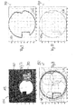
- Fig. 2 shows a camera image 250 of a part of the in Fig. 1
- the four circular markers 112 are each partially visible, since these are used for the experiment according to FIG Fig. 2 with occlusion objects 200 have been partially obscured.
- the according to Fig. 2 upper left circular marker 112 is only partially visible on the camera image 250.
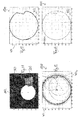
- Fig. 3 to Fig. 6 show adjustments of the according to Fig. 2 arranged on the upper left circular marker 112, which extends partially out of the camera image 250 out (see detail in Fig. 3 ).
- diagram 400 in Fig. 4 is a horizontal coordinate along an abscissa 402, along a ordinate 404 a vertical coordinate according to Fig. 2 applied.
- Fig. 4 shows that from the existing measuring points of the only partially recognizable circular marker 112 whose position and circumference were reliably identified.
- Fig. 5 shows a graph 500 with the result of fitting
- Fig. 6 shows a diagram 600, in which the hidden portion of the according to Fig. 2 left upper circular marker 112 has been added computationally.
- the detail of the camera image 250 according to Fig. 7 as well as charts 800 in Fig. 8 , 900 in Fig. 9 and 1000 in Fig. 10 correspond to the detail of the camera image 250 according to FIG Fig. 3 or the diagrams 400, 500 and 600 in Fig. 4 to Fig. 6 but refer to another circular marker 112 partially covered by occlusion structures 200, 206. Again, reliable construction of the marker 112 has been possible.
- the detail of the camera image 250 according to Fig. 11 as well as charts 1200 in Fig. 12 , 1300 in Fig. 13 and 1400 in Fig. 14 correspond to the detail of the camera image 250 according to FIG Fig. 3 or the diagrams 400, 500 and 600 in Fig. 4 to Fig. 6 , but refer to the according to Fig. 2 shown at the bottom right and by means of a masking structure 200 partially covered circular marker 112. Again, a reliable construction of the marker 112 has been possible.
- FIG. 15 The detail of the camera image 250 according to Fig. 15 as well as diagrams 1600 in Fig. 16 1700 in Fig. 17 and 1800 in Fig. 18 correspond to the detail of the camera image 250 according to FIG Fig. 3 or the diagrams 400, 500 and 600 in Fig. 4 to Fig. 6 , but refer to the according to Fig. 2 bottom left
- a circular marker 112 partially covered by a masking structure 200. Again, reliable construction of the marker 112 has been possible.
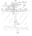
- Fig. 19 shows a double shield tunnel boring machine (TBM) 1900 as an example of a system in which a sensor arrangement according to the invention can be implemented.
- the tunnel boring machine 1900 is located according to Fig. 19 to Fig. 21 in the interior of a tunnel already partially drilled in a mountain range in 1910, 1970.
- the tunnel boring machine 1900 in particular contains a rotating drill head 1920 arranged on the front side, on which the actual cutting elements for cutting or removal of material of the rock 1910 are located.
- the drill head 1920 is fixedly and rigidly attached to the front of a front shield 1925. While the front shield 1925 does not rotate itself, the drill head 1920 rotates during the advancement and drilling of the tunnel boring machine 1900. However, in a translational displacement of the components 1920, 1925 they are rigidly coupled, so that such a movement is performed only together.
- the target plate 106 is attached to a rear side of the front shield 1925.
- Fig. 19 shows the tunnel boring machine 1900 in an initial position of a drilling cycle.
- a Gripper shield 1930 is attached to the front shield 1925 rearward.
- the front shield 1925 is translationally displaceable in the direction of advancement in relation to the Gripper shield 1930.
- This relative displacement can be generated by telescopic cylinder 1927, which is used for advancing or for propulsion of the front shield 1925 in an in Fig. 20 shown deflected position can be brought.
- the tunnel boring machine 1900 moves vividly similar to an earthworm along the borehole 1970.
- the relative position between the front shield 1925 and Gripper Shield 1930 changes continuously during operation, see also Fig. 20 ,
- Fig. 21 shows the advance from the articulation shield 1969 ("ariculation shield") at the end of a stroke to gain access to the 1910 mountains.
- Fig. 20 shows the tunnel boring machine 1900 in a position in which the telescopic cylinder 1927 are extended, which has a propulsion of the front plate 1925 result.
- the articulation plate 1969 with articulation cylinders 1967 is not pulled along during the forward movement of the front plate 1925.
- the Gripper Shield 1930 has cylinders that brace themselves against the mountain.
- the rotating cutting wheel of the drill head 1920 rotates relative to the front shield 1925, but the drill head 1920 is fixedly mounted on the front shield 1925.
- the front cutting shield of the tunnel boring machine 1900 is thereby pressed against the mountain and carries it off. In this case, the relative distance between the front shield 1925 and Gripper shield 1930 changes, with their relative position to each other by means of the sensor arrangement is determined.
- the camera 114 is fixedly mounted on the gripper shield 1930, whereas the target plate 106 is fixedly secured to the back of the front shield 1925, which in turn can only be moved in unison with the drill head 1920.
- the detector assembly 108 is attached to a front of the Gripper Shield 1930.
- Fig. 19 to Fig. 21 also show an erector in 1995 which is used to pick up concrete blocks called tubbings in 1997 and to gradually attach them to the drilled borehole wall in 1970 so as to line and thus stabilize them.
- a shaft 1999 serves to transmit rotational energy to the boring head 1920.
- Torque reaction cylinders 1991 also serve to transmit the torque.
- theodolites can be georeferenced a position of the Gripper Shield 1930 geo-referenced.
- a theodolite may have a laser that can rotate alternately looking backwards or looking forward and by means of a Laser beam and the detection of markings on the tunnel boring machine 1900 determines the absolute position of the Gripper Shield 1930.
- theodolite not easy to determine the position of the front shield 1925 and the coupled therewith drill head 1920, since both do not allow backward continuous view.
- the absolute position of the Gripper Shield 1925 can also be determined using the absolute position of the Gripper Shield 1930 measured with the theodolite.
- Such absolute positions can be related in particular to a tunnel axis.
- the control of the tunnel boring machine 1900 takes place on the basis of the determined position of the front shield 1925 or the drill head 1920 coupled thereto
- Fig. 22 shows a gas production platform 2200.
- Natural gas from the seabed 2202 is conveyed by a riser 2210 to the oil rig 2220.
- a fir tree 2250 also called a Christmas tree
- the cross of eruption 2250 includes a gauge 2252 and flanges 2254, 2256.
- a pipeline 2258 is flanged.
- Fig. 23 shows a spatial view of a portion of a sensor assembly according to an exemplary embodiment, in which two in different planes and at a defined distance from each other mounted support plates 110 ', 110 "with marker structures 112 used become.
- Fig. 24 shows a plan view of the part of the sensor assembly according to Fig. 23 ,
- the electromagnetic radiation non-reflecting support structure 110 is according to Fig. 23 by the two interconnected by connecting rods 2300 and thereby spaced from each other in the spacing direction between the components (of which in Fig. 23 only component 102 is shown) spaced apart support plates 110 ', 110 "are formed on the support plate 110.
- At the support plate 110" three marker circles are formed at corners of an imaginary equilateral triangle and is additional another marker circle formed at the center of the triangle.
- the support plate 110 ' is directly attached to the first component 102, and the support plate 110 "is indirectly attached to the first component 102 by means of the connecting rods 2300.
- Electromagnetic radiation detection means mounted on the second component 104 detect a varying relative size ratio of the marker circles on the support plate 110 'and on the support plate 110 "If a detection unit knows the actual physical size of the marker circuits on the support plates 110, 110", then this information may be known also derived steric information.
- the use of a plurality of carrier plates 110 ', 110 “generally enables the determination of six translatory or rotational degrees of freedom, which have a relative position between the two components 102, 104 and thus also between the carrier plates 110', 110" and the second component 104 accompanied.
- an in FIGS. 23 and 24 Detection means 118 determine the spatial relationship between the components 102, 104 using the detected electromagnetic radiation from only a subset of marker features of the marker 112 (eg, using only the marker circles on the backing plate 110 ") and based on previously known ones make geometric data regarding only this subset of the marker structures of the marker device 112. Should one or more of the marker circles of the support plate 110 'be temporarily or permanently invisible to the electromagnetic radiation detector by soiling, covering or obscuring, the detection means 118 may extract additional information necessary for complete evaluation to, for example, redundantly provided marker circles of the support plate 110'.
Landscapes
- Engineering & Computer Science (AREA)
- Physics & Mathematics (AREA)
- Mining & Mineral Resources (AREA)
- General Physics & Mathematics (AREA)
- General Life Sciences & Earth Sciences (AREA)
- Life Sciences & Earth Sciences (AREA)
- Environmental & Geological Engineering (AREA)
- Geochemistry & Mineralogy (AREA)
- Geology (AREA)
- Electromagnetism (AREA)
- Radar, Positioning & Navigation (AREA)
- Remote Sensing (AREA)
- Length Measuring Devices By Optical Means (AREA)
- Geophysics And Detection Of Objects (AREA)
Applications Claiming Priority (1)
| Application Number | Priority Date | Filing Date | Title |
|---|---|---|---|
| DE202012102496U DE202012102496U1 (de) | 2012-07-05 | 2012-07-05 | Fehlerrobuste Sensorik zum Ermitteln einer räumlichen Beziehung zwischen Anlagenkomponenten unter rauen Bedingungen |
Publications (2)
| Publication Number | Publication Date |
|---|---|
| EP2682563A2 true EP2682563A2 (fr) | 2014-01-08 |
| EP2682563A3 EP2682563A3 (fr) | 2016-03-23 |
Family
ID=47020044
Family Applications (1)
| Application Number | Title | Priority Date | Filing Date |
|---|---|---|---|
| EP13175153.9A Withdrawn EP2682563A3 (fr) | 2012-07-05 | 2013-07-04 | Système de détection résistant aux erreurs pour la détermination d'une relation spatiale entre des composants d'une installation dans des conditions difficiles |
Country Status (2)
| Country | Link |
|---|---|
| EP (1) | EP2682563A3 (fr) |
| DE (1) | DE202012102496U1 (fr) |
Cited By (1)
| Publication number | Priority date | Publication date | Assignee | Title |
|---|---|---|---|---|
| CN110941002A (zh) * | 2019-12-18 | 2020-03-31 | 哈尔滨工程大学 | 一种自适应抗差的序贯最小二乘精密单点定位方法 |
Families Citing this family (1)
| Publication number | Priority date | Publication date | Assignee | Title |
|---|---|---|---|---|
| AT14252U1 (de) * | 2013-07-30 | 2015-07-15 | Montanuniversität Leoben | System zum Ermitteln eines Ortsbrustbilds |
Family Cites Families (4)
| Publication number | Priority date | Publication date | Assignee | Title |
|---|---|---|---|---|
| JPH04127014A (ja) * | 1990-09-18 | 1992-04-28 | Aoki Corp | シールド測量方法 |
| EP1153292B1 (fr) * | 1998-12-23 | 2011-08-24 | Image Guided Technologies, Inc. | Sonde hybride 3-d localisee par des capteurs multiples |
| US6288785B1 (en) * | 1999-10-28 | 2001-09-11 | Northern Digital, Inc. | System for determining spatial position and/or orientation of one or more objects |
| JP4062631B2 (ja) * | 2005-11-29 | 2008-03-19 | 鹿島建設株式会社 | 筒状リングの歪み形状計測方法及びプログラム |
-
2012
- 2012-07-05 DE DE202012102496U patent/DE202012102496U1/de not_active Expired - Lifetime
-
2013
- 2013-07-04 EP EP13175153.9A patent/EP2682563A3/fr not_active Withdrawn
Non-Patent Citations (1)
| Title |
|---|
| MATTHEW HARKER; PAUL O'LEARY: "ICVGIP 2006, LNCS", vol. 4338, 2006, article "Direct Estimation of Homogeneous Vectors: An III-Solved Problem in Computer Vision", pages: 919 - 930 |
Cited By (1)
| Publication number | Priority date | Publication date | Assignee | Title |
|---|---|---|---|---|
| CN110941002A (zh) * | 2019-12-18 | 2020-03-31 | 哈尔滨工程大学 | 一种自适应抗差的序贯最小二乘精密单点定位方法 |
Also Published As
| Publication number | Publication date |
|---|---|
| DE202012102496U1 (de) | 2012-09-13 |
| EP2682563A3 (fr) | 2016-03-23 |
Similar Documents
| Publication | Publication Date | Title |
|---|---|---|
| DE60314598T2 (de) | Ein gelenkarm für eine tragbare koordinatenmessmaschine | |
| DE19528465C2 (de) | Verfahren und Vorrichtung zur schnellen Erfassung der Lage einer Zielmarke | |
| DE69915156T2 (de) | Automatische Führungs- und Meßvorrichtung | |
| EP1171752B1 (fr) | Determination de position indirecte au moyen d'un dispositif de poursuite | |
| EP2810019B1 (fr) | Système de mesure doté d'un appareil de mesure et d'un module de balayage | |
| DE102011077080A1 (de) | System für zweidimensionale Grundriss- und Punktübertragung | |
| DE112013005525B4 (de) | Messvorrichtung | |
| EP2248636B1 (fr) | Système et un procédé de mesure d'un manipulateur | |
| DE102008010916A1 (de) | Verfahren und Vorrichtung zur Ermittlung einer Ausrichtung von zwei drehbar gelagerten Maschinenteilen, einer Ausrichtung von zwei hohlzylinderförmigen Maschinenteilen oder zur Prüfung einer Komponente auf Geradheit entlang einer Längsseite | |
| WO2012136345A2 (fr) | Système et procédé de représentation visuelle d'informations sur des objets réels | |
| EP1593930B1 (fr) | Dispositif et procédé pour mesurer des objets | |
| DE102010021839A1 (de) | Verfahren zur Maschinenvermessung | |
| AU2011334831B2 (en) | Method for controlling drilling unit of rock drilling rig, and rock drilling rig | |
| EP2824525B1 (fr) | Procédé et dispositif de détermination de la position de moyens de fonctionnement d'une installation d'automatisation industrielle | |
| EP1724549A2 (fr) | Procédé destiné à la détermination des coordonnées en 3D de la surface d'un objet | |
| DE102012001446A1 (de) | Anordnung und Verfahren zum Messen der Verformung einer Welle | |
| DE102016200877A1 (de) | System zum Messen einer dreidimensionalen Position | |
| DE68913578T2 (de) | Gerät zur Positionsbestimmung für einen sich unter Wasser bewegenden Körper. | |
| EP2682563A2 (fr) | Système de détection résistant aux erreurs pour la détermination d'une relation spatiale entre des composants d'une installation dans des conditions difficiles | |
| DE69416386T2 (de) | System zur Messung dreidimensionaler Verschiebungen | |
| EP2458206A1 (fr) | Dispositif et procédé de mesure de la déformation d'une pale de rotor lors d'une charge et compensation de l'erreur | |
| DE102011055119A1 (de) | Vorrichtung und Verfahren zur Bestimmung der Orientierung zweier über zwei Kreuzgelenke und eine dritte Welle verbundener Wellen mit einem Drehgelenk | |
| DE102014104514A1 (de) | Verfahren zur Messdatenvisualisierung und Vorrichtung zur Durchführung des Verfahrens | |
| DE102006023926A1 (de) | Vorrichtung und Verfahren zur quantitativen Beurteilung der räumlichen Lage zweier Maschinenteile, Wellen, Spindeln, Werkstücke oder anderer Gegenstände relativ zueinander | |
| EP2740895A2 (fr) | Capteur de distance de cuvelage pour tunnelier |
Legal Events
| Date | Code | Title | Description |
|---|---|---|---|
| PUAI | Public reference made under article 153(3) epc to a published international application that has entered the european phase |
Free format text: ORIGINAL CODE: 0009012 |
|
| AK | Designated contracting states |
Kind code of ref document: A2 Designated state(s): AL AT BE BG CH CY CZ DE DK EE ES FI FR GB GR HR HU IE IS IT LI LT LU LV MC MK MT NL NO PL PT RO RS SE SI SK SM TR |
|
| AX | Request for extension of the european patent |
Extension state: BA ME |
|
| RIN1 | Information on inventor provided before grant (corrected) |
Inventor name: O'LEARY, PAUL Inventor name: HARKER, MATTHEW Inventor name: GOLSER, JOHANN |
|
| PUAL | Search report despatched |
Free format text: ORIGINAL CODE: 0009013 |
|
| AK | Designated contracting states |
Kind code of ref document: A3 Designated state(s): AL AT BE BG CH CY CZ DE DK EE ES FI FR GB GR HR HU IE IS IT LI LT LU LV MC MK MT NL NO PL PT RO RS SE SI SK SM TR |
|
| AX | Request for extension of the european patent |
Extension state: BA ME |
|
| RIC1 | Information provided on ipc code assigned before grant |
Ipc: E21D 9/00 20060101AFI20160216BHEP Ipc: E21B 33/035 20060101ALI20160216BHEP Ipc: G01S 5/16 20060101ALI20160216BHEP Ipc: G01B 11/27 20060101ALI20160216BHEP |
|
| STAA | Information on the status of an ep patent application or granted ep patent |
Free format text: STATUS: THE APPLICATION IS DEEMED TO BE WITHDRAWN |
|
| 18D | Application deemed to be withdrawn |
Effective date: 20160924 |