EP2682602B1 - Pale de turbine éolienne et générateur d'électricité éolienne équipé de cette pale - Google Patents
Pale de turbine éolienne et générateur d'électricité éolienne équipé de cette pale Download PDFInfo
- Publication number
- EP2682602B1 EP2682602B1 EP12752158.1A EP12752158A EP2682602B1 EP 2682602 B1 EP2682602 B1 EP 2682602B1 EP 12752158 A EP12752158 A EP 12752158A EP 2682602 B1 EP2682602 B1 EP 2682602B1
- Authority
- EP
- European Patent Office
- Prior art keywords
- blade
- wind turbine
- maximum
- tip
- region
- Prior art date
- Legal status (The legal status is an assumption and is not a legal conclusion. Google has not performed a legal analysis and makes no representation as to the accuracy of the status listed.)
- Active
Links
Images




Classifications
-
- F—MECHANICAL ENGINEERING; LIGHTING; HEATING; WEAPONS; BLASTING
- F03—MACHINES OR ENGINES FOR LIQUIDS; WIND, SPRING, OR WEIGHT MOTORS; PRODUCING MECHANICAL POWER OR A REACTIVE PROPULSIVE THRUST, NOT OTHERWISE PROVIDED FOR
- F03D—WIND MOTORS
- F03D1/00—Wind motors with rotation axis substantially parallel to the air flow entering the rotor
- F03D1/06—Rotors
- F03D1/0608—Rotors characterised by their aerodynamic shape
- F03D1/0633—Rotors characterised by their aerodynamic shape of the blades
-
- F—MECHANICAL ENGINEERING; LIGHTING; HEATING; WEAPONS; BLASTING
- F03—MACHINES OR ENGINES FOR LIQUIDS; WIND, SPRING, OR WEIGHT MOTORS; PRODUCING MECHANICAL POWER OR A REACTIVE PROPULSIVE THRUST, NOT OTHERWISE PROVIDED FOR
- F03D—WIND MOTORS
- F03D1/00—Wind motors with rotation axis substantially parallel to the air flow entering the rotor
- F03D1/06—Rotors
- F03D1/0608—Rotors characterised by their aerodynamic shape
- F03D1/0633—Rotors characterised by their aerodynamic shape of the blades
- F03D1/0641—Rotors characterised by their aerodynamic shape of the blades of the section profile of the blades, i.e. aerofoil profile
-
- F—MECHANICAL ENGINEERING; LIGHTING; HEATING; WEAPONS; BLASTING
- F05—INDEXING SCHEMES RELATING TO ENGINES OR PUMPS IN VARIOUS SUBCLASSES OF CLASSES F01-F04
- F05B—INDEXING SCHEME RELATING TO WIND, SPRING, WEIGHT, INERTIA OR LIKE MOTORS, TO MACHINES OR ENGINES FOR LIQUIDS COVERED BY SUBCLASSES F03B, F03D AND F03G
- F05B2260/00—Function
- F05B2260/96—Preventing, counteracting or reducing vibration or noise
-
- Y—GENERAL TAGGING OF NEW TECHNOLOGICAL DEVELOPMENTS; GENERAL TAGGING OF CROSS-SECTIONAL TECHNOLOGIES SPANNING OVER SEVERAL SECTIONS OF THE IPC; TECHNICAL SUBJECTS COVERED BY FORMER USPC CROSS-REFERENCE ART COLLECTIONS [XRACs] AND DIGESTS
- Y02—TECHNOLOGIES OR APPLICATIONS FOR MITIGATION OR ADAPTATION AGAINST CLIMATE CHANGE
- Y02E—REDUCTION OF GREENHOUSE GAS [GHG] EMISSIONS, RELATED TO ENERGY GENERATION, TRANSMISSION OR DISTRIBUTION
- Y02E10/00—Energy generation through renewable energy sources
- Y02E10/70—Wind energy
- Y02E10/72—Wind turbines with rotation axis in wind direction
-
- Y—GENERAL TAGGING OF NEW TECHNOLOGICAL DEVELOPMENTS; GENERAL TAGGING OF CROSS-SECTIONAL TECHNOLOGIES SPANNING OVER SEVERAL SECTIONS OF THE IPC; TECHNICAL SUBJECTS COVERED BY FORMER USPC CROSS-REFERENCE ART COLLECTIONS [XRACs] AND DIGESTS
- Y10—TECHNICAL SUBJECTS COVERED BY FORMER USPC
- Y10S—TECHNICAL SUBJECTS COVERED BY FORMER USPC CROSS-REFERENCE ART COLLECTIONS [XRACs] AND DIGESTS
- Y10S416/00—Fluid reaction surfaces, i.e. impellers
- Y10S416/02—Formulas of curves
Definitions
- the present invention relates to a wind turbine blade and a wind turbine generator including a wind turbine blade.
- a wind turbine generator has wind turbine blades rotating around an axis by the force of wind and generates power by converting the rotational force to electric power.
- the power generated by the wind turbine generator is a product of the shaft-end output (power generated by the blades) multiplied by the conversion efficiency (efficiency of the bearings and generator).
- the shaft-end output is given by the expression below. Power generation is increased by using blades with high blade efficiency and a large blade diameter.
- shaft - end output 1 / 2 ⁇ air density ⁇ wind speed ⁇ ⁇ 3 ⁇ blade efficiency ⁇ ⁇ ⁇ blade diameter / 2 ⁇ ⁇ 2
- the actual upper limit is approximately 0.5 due to the influence of the wind turbine wake and air resistance of the blades. Thus, it is difficult to significantly improve the blade efficiency further.
- a wind turbine blade has a predetermined optimal chord length corresponding to a certain tip speed ratio and satisfies the relationship represented by the following expression ( Wind Energy Handbook, John Wiley & Sons, p. 378 ): Copt / R ⁇ ⁇ 2 ⁇ CLdesign ⁇ r / R ⁇ 16 / 9 ⁇ ⁇ / n
- Copt is the optimal chord length
- R (blade radius) is 1/2 of the blade diameter
- A is the design tip-speed ratio
- CLdesign is the design lift coefficient
- r is the radial position of a blade cross-section
- n is the number of blades.
- the design tip-speed ratio is the ratio of blade-tip speed to infinite upstream wind speed.
- the design lift coefficient is a lift coefficient for the angle-of-attack corresponding to a maximum lift-to-drag ratio (lift/drag) of an airfoil (blade cross-section) and is determined in accordance with the (aerodynamic) shape of the airfoil (blade cross-section) and the inflow condition (Reynolds number).
- Fig. 13 illustrates the definition of the Reynolds number used in this specification.
- PTL 1 discloses an airfoil for increasing the wind-turbine power output. Specifically, it discloses an airfoil having a blade thickness ratio in the range of 14% to 45% and a design lift coefficient in the range of 1.10 to 1.25 (refer to Claim 1).
- US 2 709 052 discloses spanwise flow control of fluid swept lifting surfaces.
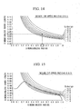
- Fig. 14 illustrates the relationship represented by Expression (1).
- the horizontal axis represents the dimensionless radius
- the vertical axis represents the dimensionless chord length.
- the dimensionless radius (r/R) is the ratio of radial position r of a blade cross-section measured from the rotation center to blade radius R.
- the dimensionless chord length (c/R) is the ratio of chord length c of a blade cross-section to blade radius R.
- Fig. 14 illustrates multiple curves representing Expression (1) with a constant design lift coefficient CLdesign. Since the curves with a constant design lift coefficient CLdesign satisfy Expression (1), an optimal chord length (vertical axis) at a specific design tip-speed ratio can be determined in consideration of the aerodynamic characteristics. In Fig. 14 , the design tip-speed ratio is within the range of 8.0 to 8.5, inclusive, and the Reynolds number is within the range of 3,000,000 to 10,000,000, inclusive.
- Fig. 15 illustrates the optimal chord-length distribution determined by Expression (1) and the actual chord-length distribution (thick line).
- the difference between the optimal chord length and the actual chord length inevitably becomes large because the actual chord length goes asymptotically to zero, causing a loss of efficiency.
- the present invention has been conceived in light of such circumstances and provides a wind turbine blade and a wind turbine generator including a wind turbine blade that can improve aerodynamic performance in the blade-tip region and reduce aerodynamic noise.
- the wind turbine blade and the wind turbine generator including a wind turbine blade according to the present invention provide the following solutions.
- a wind turbine blade according to claim 1 is provided.
- the present invention takes into account the fact that, for a wind turbine blade whose rotation center is at the blade root, the edge moment is small at the blade tip compared with the edge moment at the blade root, and thus, even when the maximum-blade-thickness position is close to the leading edge, the strength near the trailing edge will not be a significant problem.
- the maximum-blade-thickness position in the blade-tip region in which the dimensionless radial is set within the range of 0.6 to 1.0, inclusive is closer to the leading edge than the maximum-blade-thickness position in the blade-body region in which the dimensionless radial position is smaller than 0.6.
- the aerodynamic performance of the blade-tip region is improved, and aerodynamic noise at the blade-tip region where the tip speed is the greatest, which is the main cause of noise, can be effectively reduced.
- the maximum-blade-thickness position is shifted in the direction of the leading edge toward the blade tip.
- the aerodynamic performance can be improved by increasing the design lift coefficient and maximum lift-to-drag ratio as a result of shifting the maximum-blade-thickness positions in the direction of the leading edge as one goes toward the blade tip.
- aerodynamic noise can be effectively reduced in the blade tip area, where the tip speed and noise are great.
- the dimensionless radial position be set within a range of 0.6 to 0.9, inclusive, and the maximum-blade-thickness position be set within a range of 25% to 40% chord length, inclusive, and the maximum-blade-thickness position be set within the range of 10% to 30% chord length, inclusive, when the dimensionless radial position is 1.0.
- the dimensionless radial position be set within a range of 0.7 to 0.85, inclusive, and the maximum-blade-thickness position be set within a range of 26% to 36% chord length, inclusive, and the maximum-blade-thickness position be set within the range of 20% to 30% chord length, inclusive, where the dimensionless radial position is 1.0.
- the leading edge in the blade-tip region may be shifted in the direction of the trailing edge such that a maximum-blade-thickness line connecting the maximum-blade-thickness positions of the blade cross-sections at radial positions form a substantially straight line.
- a beam which provides most of the strength of the wind turbine blade, connects the maximum-blade-thickness positions and extends in the radial direction.
- the maximum-blade-thickness line which is formed by connecting, in the radial direction, the maximum-blade-thickness positions of the blade cross-sections at corresponding radial positions, be a substantially straight line in the radial direction.
- the maximum-blade-thickness line can be maintained as a substantially straight line in the radial direction.
- the leading edge of the wind turbine blade according to the present invention is shaped like a letter S such that it is largely shifted in the direction of the trailing edge in a transitional region from the blade-body region to the blade-tip region, is gradually shifted in the direction of the trailing edge toward the blade tip, and finally, is shifted in the direction of the trailing edge to connect to the blade tip.
- the trailing edge can be rounded with a greater curvature. In this way, the angular position at which aerodynamic noise generated at the trailing edge in the blade-tip region can be shifted in the blade radius direction, and noise can be reduced even more.
- the cross-sectional shape of the blade tip may be a symmetrical airfoil.
- the cross-section at the blade tip is a symmetrical airfoil, i.e., an airfoil having zero camber.
- the blade tip area having a thin and complicated shape that is normally difficult to manufacture, can be manufactured easily.
- the cambers of airfoils close to the blade tip in the blade-tip region gradually approach zero in the direction of the blade tip and reach zero at the blade tip.
- a wind turbine generator includes one of the wind turbine blades described above; a rotor connected to a blade root of the wind turbine blade and rotated by the wind turbine blade; and a generator configured to convert a rotational force received by the rotor to electric power.
- maximum-blade-thickness positions in the blade-tip region are closer to the leading edge than maximum-blade-thickness positions in the blade-body region. Accordingly, the aerodynamic performance of the blade-tip region can be improved, and the aerodynamic noise at the blade-tip region can be effectively reduced.
- a wind turbine blade and a wind turbine generator including a wind turbine blade according to embodiments of the present invention will be described below with reference to the drawings.
- a wind turbine blade according to the first embodiment is suitable for use as a blade of a wind turbine generator.
- three wind turbine blades are radially connected to a rotor and are disposed approximately 120 degrees apart.
- the wind turbine blade is a thin blade having a rotating diameter (blade diameter) of 60 m or more and solidity (projected area of entire blade divided by area swept by blade) within the range of 0.2 to 0.6, inclusive.
- the pitch of the wind turbine blade may be variable or fixed.
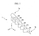
- a wind turbine blade 1 is a three-dimensional blade extending from a blade root la, which is the end closer to the rotation center, to a blade tip 1b.
- Fig. 1 illustrates that the shape of the wind turbine blade is defined by blade element cross-sections taken at radial positions corresponding to blade thickness ratios of 18%, 21%, 24%, 30%, 36%, and 42%.
- the radial positions of the wind turbine blade 1 may be the radial positions r corresponding to the distances from the rotation center of the blade (or a dimensionless radial position r/R, which is the ratio of radial position to blade radius).
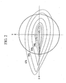
- Fig. 2 illustrates a projection of the blade element cross-sections in Fig. 1 onto the XY plane (the plane orthogonal to the Z axis).
- the leading edge of the blade is on the right side, and the trailing edge of the blade is on the left side in Fig. 2 .
- the wind turbine blade is shaped such that the chord length decreases from the blade root to the blade tip.
- the wind turbine blade 1 has a blade-tip region 3 in which dimensionless radial positions r/R, which is the ratio of radial position r to blade radius R (1/2 of the blade diameter), is within the range of 0.6 to 1.0, inclusive, and a blade-body region 5 in which dimensionless radial positions are less than 0.6.
- the maximum-blade-thickness positions of the blade cross-sections in the blade-tip region 3 is closer to the leading edge 9 than the maximum-blade-thickness positions of the blade cross-sections in the blade-body region 5.
- the maximum-blade-thickness positions shift from the blade root side to the blade tip side, e.g., the chord length varies, starting from 40% and decreasing to 36%, 30%, 24%, and 20%, where the chord length at the leading edge is defined as 0%, and the chord length of the trailing edge is defined as 100%.
- Line segments L1 in Fig. 5 represent the maximum-blade-thickness positions.
- a maximum-blade-thickness position in the blade-body region 5 corresponds to a chord length of 40% or more.
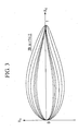
- the maximum-blade-thickness position be gradually shifted in the direction of the leading edge 9 as one goes toward the blade tip 7 (see Fig. 4 ).
- the maximum-blade-thickness positions in the blade-tip region 3 are set within the range of 25% to 40% chord length, inclusive, in a region in which the dimensionless radial positions are within the range of 0.6 to 0.9, inclusive, and are set within the range of 10% to 30% chord length, inclusive, where the dimensionless radial position is 1.0 (i.e., at the blade tip 7).
- the maximum-blade-thickness positions in the blade-tip region 3 are set within the range of 26% to 36% chord length, inclusive, in a region in which the dimensionless radial positions are within the range of 0.7 to 0.85, inclusive, and are set within the range of 20% to 30% chord length, inclusive, where the dimensionless radial position is 1.0.
- the blade tip 7 has a symmetric airfoil. That is, the airfoil has zero camber. In this way, the blade tip area, having a thin and complicated shape that is normally difficult to manufacture, can be manufactured easily.
- the cambers of airfoils close to the blade tip 7 in the blade-tip region 3 gradually approach zero toward the blade tip 7 and reach zero at the blade tip 7.
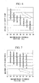
- Figs. 6 to 8 illustrate results of a numerical simulation conducted on airfoils with varying maximum-blade-thickness positions in the range of 24% to 36% chord length.
- the conditions for the numerical simulation included a design tip-speed ratio within the range of 8.0 to 8.5, inclusive, and a Reynolds number within the range of 3,000,000 to 10,000,000, inclusive.
- the aerodynamic performance improves as a result of an increase in the design lift coefficient and maximum lift-to-drag ratio, and noise is reduced as a result of a reduction in the boundary layer thickness (displacement thickness).
- the trailing edge 11 becomes relatively thin, and the strength of the trailing edge 11 against edge moment, which occurs due to the load exerted on the wind turbine blade 1, may decrease.
- This design takes into account the fact that strength near the trailing edge 11 is not a significant problem on the blade tip 7 side even when the maximum-blade-thickness position is close to the leading edge 9 because the edge moment is smaller than the edge moment on the blade root side.
- the maximum-blade-thickness positions in the blade-tip region 3 is closer to the leading edge 9 than the maximum-blade-thickness positions in the blade-body region 5. In this way, the aerodynamic performance of the blade-tip region 3 is improved, and aerodynamic noise in the blade-tip region where the tip speed is the greatest, which is the main cause of noise, can be effectively reduced.
- the aerodynamic performance can be improved by increasing the design lift coefficient and maximum lift-to-drag ratio as a result of shifting the maximum-blade-thickness positions in the direction of the leading edge 9 as one goes toward the blade tip 7.
- aerodynamic noise can be effectively reduced near the blade tip 7, where the tip speed is great, causing an increase in noise.
- wind turbine blade 1 By applying the wind turbine blade 1 according to this design to a wind turbine generator including a rotor connected to the blade root of the wind turbine blade and rotated by the wind turbine blade and a generator that converts the rotational force of the rotor to electric power, it is possible to provide a wind-power apparatus having an increased power output due to improved aerodynamic performance and generating less aerodynamic noise.
- the maximum-blade-thickness line formed by connecting the maximum-blade-thickness positions of the blade cross-sections at the radial positions in the blade radius direction is optimized in accordance with the shape of the leading edge 9 in the blade-tip region 3.
- Other configurations, i.e., setting the maximum-blade-thickness positions in the blade-tip regions closer to the leading edge than the maximum-blade-thickness positions in the blade-body region are the same. Hence, only the differences will be described below, and descriptions of similarities will be omitted.
- Fig. 9 illustrates the maximum-blade-thickness positions at certain radial positions of a wind turbine blade according to this embodiment.
- the line segment L2 in Fig. 9 represents the maximum-blade-thickness positions.
- the maximum-blade-thickness positions are set such that the angular positions at the radial positions are the same with respect to the blade rotation center. This is achieved by shifting the leading edge 9 further in the direction of the trailing edge 11 when going toward the blade tip, as illustrated in Fig. 9 .
- the maximum-blade-thickness line which is formed by connecting, in the radial direction, the maximum-blade-thickness positions of the blade cross-sections at the radial positions, is a substantially straight line along the radial direction of the wind turbine blade.
- Fig. 10 illustrates the substantially straight maximum-blade-thickness line 13 formed by shifting the leading edge 9 in the direction of the trailing edge 11, as illustrated in Fig. 9 .
- the leading edge 9 in the blade-tip region 3 is S-shaped such that the leading edge 9 shifts greatly toward the trailing edge 11 in a transition region 15 from the blade-body region 5 to the blade-tip region 3, shifts gradually in the direction of the trailing edge toward the blade tip 7 in a connecting region 16, which is connected to the transition region 15, and shifts in the direction of the trailing edge 11 to finally connect with the blade tip 7 in an end region 17, which is connected to the connecting region 16.
- a beam which provides most of the strength of the wind turbine blade, extends in the radial direction at the maximum-blade-thickness positions.
- the maximum-blade-thickness line 13' extends straight along the radial direction. Providing a straight beam facilitates manufacturing.
- the maximum-blade-thickness positions in the blade-body region are the same as the maximum-blade-thickness positions in the blade-tip region.
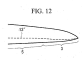
- the maximum-blade-thickness line 13" is unable to maintain a straight line and curves in the blade-tip region 3, as illustrated in Fig 12 .
- the maximum-blade-thickness line 13 is a substantially straight line set by shifting the leading edge 9 in the direction of the trailing edge 11 (see Fig. 10 ). In this way, a substantially straight beam can be used, facilitating manufacturing. If a receptor, which is a lightning strike point, is disposed at a maximum-blade-thickness position, the receptor can be disposed in a substantially straight line, facilitating manufacturing.
- the trailing edge 11 can be rounded with a larger curvature by shifting the leading edge 9 in the direction of the trailing edge 11 (in particular, shaping the leading edge 9 like a letter S) in the blade-tip region 3, as described in this embodiment (region 19 in Fig. 10 ). In this way, the angular position at which aerodynamic noise generated at the trailing edge 11 in the blade-tip region 3 can be shifted in the blade radius direction, and noise can be reduced even more.
- the design tip-speed ratio is set within the range of 8.0 to 8.5, inclusive.
- the design tip-speed ratio in the present invention is not limited and may be set, for example, within the range of 6.0 to 9.0, inclusive.
Landscapes
- Engineering & Computer Science (AREA)
- Physics & Mathematics (AREA)
- Fluid Mechanics (AREA)
- Life Sciences & Earth Sciences (AREA)
- Sustainable Development (AREA)
- Sustainable Energy (AREA)
- Chemical & Material Sciences (AREA)
- Combustion & Propulsion (AREA)
- Mechanical Engineering (AREA)
- General Engineering & Computer Science (AREA)
- Wind Motors (AREA)
Claims (6)
- Pale d'éolienne (1) comportant :un corps de pale ayant une longueur de corde qui diminue depuis un côté de pied de pale jusqu'à un côté de bout de pale,le corps de pale comprendune zone de bout de pale (3) dans laquelle une position radiale sans dimension est dans la plage de 0,6 à 1,0, inclus, la position radiale sans dimension étant le rapport de la position radiale sur le rayon de pale qui est 1/2 d'un diamètre de pale, etune zone de corps de pale (5) dans laquelle la position radiale sans dimension est inférieure à 0,6, etune position d'épaisseur de pale maximum d'une section transversale de pale dans la zone de bout de pale (3) est plus près d'un bord d'attaque (9) qu'une position d'épaisseur de pale maximum d'une section transversale de pale dans la zone de corps de pale (5) quand la longueur de corde au niveau du bord d'attaque (9) est définie comme 0 pour cent, et la longueur de corde d'un bord de fuite (11) est définie comme 100 pour cent, dans chacune des sections transversales de pale, la pale d'éolienne étant caractérisée en ce quele bord d'attaque (9) dans la zone de bout de pale (3) est décalé dans la direction du bord de fuite (11) de telle sorte qu'une ligne d'épaisseur de pale maximum (13) formée en reliant, dans la direction radiale, les positions d'épaisseur de pale maximum des sections transversales de pale au niveau de positions radiales forme une ligne sensiblement droite, et dans laquellele bord d'attaque dans la zone de bout de pale est en forme de S de telle sorte que le bord d'attaque se décale fortement vers le bord de fuite dans une zone de transition depuis la zone de corps de pale jusqu'à la zone de bout de pale, se décale progressivement dans la direction du bord de fuite vers le bout de pale dans une zone de raccordement, qui est reliée à la zone de transition, et se décale dans la direction du bord de fuite pour se raccorder finalement au bout de pale dans une zone d'extrémité, qui est reliée à la zone de raccordement.
- Pale d'éolienne (1) selon la revendication 1, dans laquelle, dans la zone de bout de pale (3), la position d'épaisseur de pale maximum est décalée dans la direction du bord d'attaque (9) vers le bout de pale (7).
- Pale d'éolienne (1) selon la revendication 2, dans laquelle,
la position d'épaisseur de pale maximum est prévue dans une plage de 25% à 40% de longueur de corde, inclus, dans une zone dans laquelle la position radiale sans dimension est prévue dans une plage de 0,6 à 0, 9, inclus, et
la position d'épaisseur de pale maximum est prévue dans la plage de 10% à 30% de longueur de corde, inclus, dans laquelle la position radiale sans dimension est 1,0. - Pale d'éolienne (1) selon la revendication 3, dans laquelle
la position d'épaisseur de pale maximum est prévue dans une plage de 26% à 36% de longueur de corde, inclus, dans une zone dans laquelle la position radiale sans dimension est prévue dans une plage de 0,7 à 0,85, inclus, et
la position d'épaisseur de pale maximum est prévue dans la plage de 20% à 30% de longueur de corde, inclus, dans laquelle la position radiale sans dimension est 1,0. - Pale d'éolienne (1) selon l'une quelconque des revendications 1 à 4 dans laquelle la forme d'une section transversale au niveau du bout de pale (1B) est un profil d'aile symétrique.
- Eolienne caractérisée en ce qu'elle comporte :une pale d'éolienne (1) selon l'une quelconque des revendications 1 à 5 ;un rotor relié à un pied de pale de la pale d'éolienne (1) et entraîné en rotation par la pale d'éolienne (1) ; etun générateur configuré pour convertir une force de rotation reçue par le rotor en énergie électrique.
Applications Claiming Priority (2)
| Application Number | Priority Date | Filing Date | Title |
|---|---|---|---|
| JP2011043189A JP5479388B2 (ja) | 2011-02-28 | 2011-02-28 | 風車翼およびこれを備えた風力発電装置 |
| PCT/JP2012/054664 WO2012117979A1 (fr) | 2011-02-28 | 2012-02-24 | Pale de turbine éolienne et générateur d'électricité éolienne équipé de cette pale |
Publications (3)
| Publication Number | Publication Date |
|---|---|
| EP2682602A1 EP2682602A1 (fr) | 2014-01-08 |
| EP2682602A4 EP2682602A4 (fr) | 2014-04-02 |
| EP2682602B1 true EP2682602B1 (fr) | 2015-06-10 |
Family
ID=46757916
Family Applications (1)
| Application Number | Title | Priority Date | Filing Date |
|---|---|---|---|
| EP12752158.1A Active EP2682602B1 (fr) | 2011-02-28 | 2012-02-24 | Pale de turbine éolienne et générateur d'électricité éolienne équipé de cette pale |
Country Status (5)
| Country | Link |
|---|---|
| US (1) | US8801387B2 (fr) |
| EP (1) | EP2682602B1 (fr) |
| JP (1) | JP5479388B2 (fr) |
| KR (1) | KR20130107370A (fr) |
| WO (1) | WO2012117979A1 (fr) |
Cited By (2)
| Publication number | Priority date | Publication date | Assignee | Title |
|---|---|---|---|---|
| EP4628724A1 (fr) | 2024-04-04 | 2025-10-08 | Nordex Energy SE & Co. KG | Une pale de rotor d'éolienne avec une section d'extrémité |
| EP4656871A1 (fr) | 2024-05-28 | 2025-12-03 | Nordex Energy SE & Co. KG | Une pale de rotor d'éolienne |
Families Citing this family (15)
| Publication number | Priority date | Publication date | Assignee | Title |
|---|---|---|---|---|
| ES2966169T3 (es) * | 2010-07-16 | 2024-04-18 | Lm Wind Power As | Pala de turbina eólica con hombro estrecho y perfiles de perfil alar relativamente gruesos |
| CN104929866B (zh) * | 2010-10-22 | 2018-05-22 | 三菱重工业株式会社 | 风车翼及具备该风车翼的风力发电装置以及风车翼的设计方法 |
| GB201109412D0 (en) * | 2011-06-03 | 2011-07-20 | Blade Dynamics Ltd | A wind turbine rotor |
| DE102012206109C5 (de) * | 2012-04-13 | 2022-06-09 | Wobben Properties Gmbh | Rotorblatt einer Windenergieanlage |
| JP5995816B2 (ja) * | 2013-10-18 | 2016-09-21 | 三菱重工業株式会社 | 風車翼及び風力発電装置 |
| WO2015145723A1 (fr) * | 2014-03-28 | 2015-10-01 | 中国電力株式会社 | Pale de turbine éolienne et générateur d'énergie éolienne la comportant |
| DE102015012427A1 (de) * | 2015-09-25 | 2017-03-30 | Senvion Gmbh | Rotorblatt mit einem schalloptimierten Profil sowie Verfahren zum Herstellen eines Rotorblatts |
| DK3488101T3 (da) * | 2016-08-30 | 2023-05-01 | Siemens Gamesa Renewable Energy As | Strømningsregulerende indretning til en vindmøllerotorvinge |
| JP6783212B2 (ja) * | 2017-10-20 | 2020-11-11 | 三菱重工業株式会社 | 風車翼へのボルテックスジェネレータの配置位置決定方法、風車翼アセンブリの製造方法及び風車翼アセンブリ |
| DE102017124861A1 (de) | 2017-10-24 | 2019-04-25 | Wobben Properties Gmbh | Rotorblatt einer Windenergieanlage und Verfahren zu dessen Auslegung |
| US11781522B2 (en) | 2018-09-17 | 2023-10-10 | General Electric Company | Wind turbine rotor blade assembly for reduced noise |
| DE102019119027B4 (de) * | 2019-07-12 | 2022-04-28 | Wobben Properties Gmbh | Rotorblatt und Windenergieanlage |
| US12292027B2 (en) * | 2020-06-29 | 2025-05-06 | Vestas Wind Systems A/S | Wind turbine with particular combined radius specific solidities along the rotor radius |
| ES3053844T3 (en) * | 2020-12-17 | 2026-01-27 | Vestas Wind Sys As | A pitch controlled wind turbine with blade connecting members |
| US12173684B1 (en) | 2024-03-19 | 2024-12-24 | King Fahd University Of Petroleum And Minerals | Wind turbine for a region with low wind speed |
Family Cites Families (12)
| Publication number | Priority date | Publication date | Assignee | Title |
|---|---|---|---|---|
| US2709052A (en) * | 1952-04-15 | 1955-05-24 | Charles J Fletcher | Spanwise flow control of fluid swept lifting surfaces |
| US4976587A (en) * | 1988-07-20 | 1990-12-11 | Dwr Wind Technologies Inc. | Composite wind turbine rotor blade and method for making same |
| GB2265672B (en) * | 1992-03-18 | 1995-11-22 | Advanced Wind Turbines Inc | Wind turbines |
| US6503058B1 (en) | 2000-05-01 | 2003-01-07 | Zond Energy Systems, Inc. | Air foil configuration for wind turbine |
| JP4024208B2 (ja) * | 2001-09-17 | 2007-12-19 | クリーン カーレント パワー システムズ インコーポレイテッド | 水中用ダクテッドタービン |
| JP3368537B1 (ja) * | 2001-11-08 | 2003-01-20 | 学校法人東海大学 | 直線翼型風水車 |
| MXPA04011829A (es) * | 2002-06-05 | 2005-03-31 | Wobben Aloys | Aspa de rotor de una instalacion de energia eolica. |
| JP3935804B2 (ja) * | 2002-08-26 | 2007-06-27 | 三菱重工業株式会社 | 翼及びこれを備える風力発電装置 |
| DE10319246A1 (de) * | 2003-04-28 | 2004-12-16 | Aloys Wobben | Rotorblatt einer Windenergieanlage |
| CN101263277B (zh) | 2005-07-15 | 2011-11-30 | 维斯塔斯风力系统有限公司 | 风轮机叶片 |
| US7789629B2 (en) * | 2006-12-07 | 2010-09-07 | Verdant Power | Non-fouling kinetic hydro power system axial-flow blade tip treatment |
| DE102008052858B9 (de) * | 2008-10-23 | 2014-06-12 | Senvion Se | Profil eines Rotorblatts und Rotorblatt einer Windenergieanlage |
-
2011
- 2011-02-28 JP JP2011043189A patent/JP5479388B2/ja active Active
-
2012
- 2012-02-24 WO PCT/JP2012/054664 patent/WO2012117979A1/fr not_active Ceased
- 2012-02-24 KR KR1020137022010A patent/KR20130107370A/ko not_active Ceased
- 2012-02-24 EP EP12752158.1A patent/EP2682602B1/fr active Active
- 2012-05-10 US US13/468,205 patent/US8801387B2/en active Active
Cited By (4)
| Publication number | Priority date | Publication date | Assignee | Title |
|---|---|---|---|---|
| EP4628724A1 (fr) | 2024-04-04 | 2025-10-08 | Nordex Energy SE & Co. KG | Une pale de rotor d'éolienne avec une section d'extrémité |
| WO2025209826A1 (fr) | 2024-04-04 | 2025-10-09 | Nordex Energy Se & Co. Kg | Pale de rotor d'éolienne dotée d'une section de pointe |
| EP4656871A1 (fr) | 2024-05-28 | 2025-12-03 | Nordex Energy SE & Co. KG | Une pale de rotor d'éolienne |
| WO2025247550A1 (fr) | 2024-05-28 | 2025-12-04 | Nordex Energy Se & Co. Kg | Pale de rotor d'éolienne |
Also Published As
| Publication number | Publication date |
|---|---|
| WO2012117979A1 (fr) | 2012-09-07 |
| JP5479388B2 (ja) | 2014-04-23 |
| US8801387B2 (en) | 2014-08-12 |
| KR20130107370A (ko) | 2013-10-01 |
| EP2682602A4 (fr) | 2014-04-02 |
| JP2012180771A (ja) | 2012-09-20 |
| EP2682602A1 (fr) | 2014-01-08 |
| US20120280509A1 (en) | 2012-11-08 |
Similar Documents
| Publication | Publication Date | Title |
|---|---|---|
| EP2682602B1 (fr) | Pale de turbine éolienne et générateur d'électricité éolienne équipé de cette pale | |
| EP2604856B1 (fr) | Pale de turbine éolienne, dispositif générateur d'énergie éolienne équipé de cette pale et procédé de calcul pour une pale de turbine éolienne | |
| EP2682597B1 (fr) | Procédé de conception d'une pale de turbine éolienne avec winglet | |
| EP2799710B1 (fr) | Ensemble de pale de rotor comportant des générateurs de tourbillons pour éolienne | |
| US10400744B2 (en) | Wind turbine blade with noise reducing micro boundary layer energizers | |
| EP2292926A1 (fr) | Pale d'eolienne a elements hypersustentateurs | |
| US8936435B2 (en) | System and method for root loss reduction in wind turbine blades | |
| JP5995816B2 (ja) | 風車翼及び風力発電装置 | |
| US10975837B2 (en) | Rotor blade shaped to enhance wake diffusion | |
| GB2573513A (en) | Aerofoil tip structure, particularly for a HAWT rotor blade | |
| EP3472456B1 (fr) | Pale de turbine éolienne munie de dentelures d'extrémité de pointe | |
| CN112689710B (zh) | 用于降低噪声的风力涡轮转子叶片组件 | |
| JP5433554B2 (ja) | 風車翼およびこれを備えた風力発電装置ならびに風車翼の設計方法 | |
| JP5479300B2 (ja) | 風車翼およびこれを備えた風力発電装置ならびに風車翼の設計方法 | |
| JP5675270B2 (ja) | 風車翼およびこれを備えた風力発電装置ならびに風車翼の設計方法 | |
| JP5433553B2 (ja) | 風車翼およびこれを備えた風力発電装置ならびに風車翼の設計方法 | |
| JP2018119483A (ja) | 翼及びそれを用いた風車 | |
| JP5574915B2 (ja) | 風車翼およびこれを備えた風力発電装置ならびに風車翼の設計方法 | |
| JP5574914B2 (ja) | 風車翼およびこれを備えた風力発電装置ならびに風車翼の設計方法 | |
| KR20240126100A (ko) | 표면거칠기에 둔감한 두께비 18%의 대용량 풍력터빈 블레이드용 에어포일 | |
| CN120813764A (zh) | 低噪声风力涡轮机叶片 |
Legal Events
| Date | Code | Title | Description |
|---|---|---|---|
| PUAI | Public reference made under article 153(3) epc to a published international application that has entered the european phase |
Free format text: ORIGINAL CODE: 0009012 |
|
| 17P | Request for examination filed |
Effective date: 20130822 |
|
| AK | Designated contracting states |
Kind code of ref document: A1 Designated state(s): AL AT BE BG CH CY CZ DE DK EE ES FI FR GB GR HR HU IE IS IT LI LT LU LV MC MK MT NL NO PL PT RO RS SE SI SK SM TR |
|
| A4 | Supplementary search report drawn up and despatched |
Effective date: 20140305 |
|
| RIC1 | Information provided on ipc code assigned before grant |
Ipc: F03D 11/00 20060101AFI20140227BHEP |
|
| DAX | Request for extension of the european patent (deleted) | ||
| GRAP | Despatch of communication of intention to grant a patent |
Free format text: ORIGINAL CODE: EPIDOSNIGR1 |
|
| INTG | Intention to grant announced |
Effective date: 20150126 |
|
| GRAS | Grant fee paid |
Free format text: ORIGINAL CODE: EPIDOSNIGR3 |
|
| GRAA | (expected) grant |
Free format text: ORIGINAL CODE: 0009210 |
|
| AK | Designated contracting states |
Kind code of ref document: B1 Designated state(s): AL AT BE BG CH CY CZ DE DK EE ES FI FR GB GR HR HU IE IS IT LI LT LU LV MC MK MT NL NO PL PT RO RS SE SI SK SM TR |
|
| REG | Reference to a national code |
Ref country code: GB Ref legal event code: FG4D |
|
| REG | Reference to a national code |
Ref country code: CH Ref legal event code: EP |
|
| REG | Reference to a national code |
Ref country code: AT Ref legal event code: REF Ref document number: 731026 Country of ref document: AT Kind code of ref document: T Effective date: 20150715 |
|
| REG | Reference to a national code |
Ref country code: DE Ref legal event code: R096 Ref document number: 602012007944 Country of ref document: DE |
|
| REG | Reference to a national code |
Ref country code: IE Ref legal event code: FG4D |
|
| PG25 | Lapsed in a contracting state [announced via postgrant information from national office to epo] |
Ref country code: NO Free format text: LAPSE BECAUSE OF FAILURE TO SUBMIT A TRANSLATION OF THE DESCRIPTION OR TO PAY THE FEE WITHIN THE PRESCRIBED TIME-LIMIT Effective date: 20150910 Ref country code: ES Free format text: LAPSE BECAUSE OF FAILURE TO SUBMIT A TRANSLATION OF THE DESCRIPTION OR TO PAY THE FEE WITHIN THE PRESCRIBED TIME-LIMIT Effective date: 20150610 Ref country code: LT Free format text: LAPSE BECAUSE OF FAILURE TO SUBMIT A TRANSLATION OF THE DESCRIPTION OR TO PAY THE FEE WITHIN THE PRESCRIBED TIME-LIMIT Effective date: 20150610 Ref country code: FI Free format text: LAPSE BECAUSE OF FAILURE TO SUBMIT A TRANSLATION OF THE DESCRIPTION OR TO PAY THE FEE WITHIN THE PRESCRIBED TIME-LIMIT Effective date: 20150610 |
|
| REG | Reference to a national code |
Ref country code: AT Ref legal event code: MK05 Ref document number: 731026 Country of ref document: AT Kind code of ref document: T Effective date: 20150610 |
|
| REG | Reference to a national code |
Ref country code: NL Ref legal event code: MP Effective date: 20150610 |
|
| PG25 | Lapsed in a contracting state [announced via postgrant information from national office to epo] |
Ref country code: LV Free format text: LAPSE BECAUSE OF FAILURE TO SUBMIT A TRANSLATION OF THE DESCRIPTION OR TO PAY THE FEE WITHIN THE PRESCRIBED TIME-LIMIT Effective date: 20150610 Ref country code: GR Free format text: LAPSE BECAUSE OF FAILURE TO SUBMIT A TRANSLATION OF THE DESCRIPTION OR TO PAY THE FEE WITHIN THE PRESCRIBED TIME-LIMIT Effective date: 20150911 Ref country code: BG Free format text: LAPSE BECAUSE OF FAILURE TO SUBMIT A TRANSLATION OF THE DESCRIPTION OR TO PAY THE FEE WITHIN THE PRESCRIBED TIME-LIMIT Effective date: 20150910 Ref country code: RS Free format text: LAPSE BECAUSE OF FAILURE TO SUBMIT A TRANSLATION OF THE DESCRIPTION OR TO PAY THE FEE WITHIN THE PRESCRIBED TIME-LIMIT Effective date: 20150610 |
|
| REG | Reference to a national code |
Ref country code: FR Ref legal event code: PLFP Year of fee payment: 5 |
|
| PG25 | Lapsed in a contracting state [announced via postgrant information from national office to epo] |
Ref country code: EE Free format text: LAPSE BECAUSE OF FAILURE TO SUBMIT A TRANSLATION OF THE DESCRIPTION OR TO PAY THE FEE WITHIN THE PRESCRIBED TIME-LIMIT Effective date: 20150610 |
|
| PG25 | Lapsed in a contracting state [announced via postgrant information from national office to epo] |
Ref country code: SK Free format text: LAPSE BECAUSE OF FAILURE TO SUBMIT A TRANSLATION OF THE DESCRIPTION OR TO PAY THE FEE WITHIN THE PRESCRIBED TIME-LIMIT Effective date: 20150610 Ref country code: PL Free format text: LAPSE BECAUSE OF FAILURE TO SUBMIT A TRANSLATION OF THE DESCRIPTION OR TO PAY THE FEE WITHIN THE PRESCRIBED TIME-LIMIT Effective date: 20150610 Ref country code: AT Free format text: LAPSE BECAUSE OF FAILURE TO SUBMIT A TRANSLATION OF THE DESCRIPTION OR TO PAY THE FEE WITHIN THE PRESCRIBED TIME-LIMIT Effective date: 20150610 Ref country code: PT Free format text: LAPSE BECAUSE OF FAILURE TO SUBMIT A TRANSLATION OF THE DESCRIPTION OR TO PAY THE FEE WITHIN THE PRESCRIBED TIME-LIMIT Effective date: 20151012 Ref country code: CZ Free format text: LAPSE BECAUSE OF FAILURE TO SUBMIT A TRANSLATION OF THE DESCRIPTION OR TO PAY THE FEE WITHIN THE PRESCRIBED TIME-LIMIT Effective date: 20150610 Ref country code: RO Free format text: LAPSE BECAUSE OF NON-PAYMENT OF DUE FEES Effective date: 20150610 Ref country code: IS Free format text: LAPSE BECAUSE OF FAILURE TO SUBMIT A TRANSLATION OF THE DESCRIPTION OR TO PAY THE FEE WITHIN THE PRESCRIBED TIME-LIMIT Effective date: 20151010 |
|
| REG | Reference to a national code |
Ref country code: DE Ref legal event code: R097 Ref document number: 602012007944 Country of ref document: DE |
|
| PLBE | No opposition filed within time limit |
Free format text: ORIGINAL CODE: 0009261 |
|
| STAA | Information on the status of an ep patent application or granted ep patent |
Free format text: STATUS: NO OPPOSITION FILED WITHIN TIME LIMIT |
|
| PG25 | Lapsed in a contracting state [announced via postgrant information from national office to epo] |
Ref country code: IT Free format text: LAPSE BECAUSE OF FAILURE TO SUBMIT A TRANSLATION OF THE DESCRIPTION OR TO PAY THE FEE WITHIN THE PRESCRIBED TIME-LIMIT Effective date: 20150610 Ref country code: DK Free format text: LAPSE BECAUSE OF FAILURE TO SUBMIT A TRANSLATION OF THE DESCRIPTION OR TO PAY THE FEE WITHIN THE PRESCRIBED TIME-LIMIT Effective date: 20150610 |
|
| 26N | No opposition filed |
Effective date: 20160311 |
|
| PG25 | Lapsed in a contracting state [announced via postgrant information from national office to epo] |
Ref country code: SI Free format text: LAPSE BECAUSE OF FAILURE TO SUBMIT A TRANSLATION OF THE DESCRIPTION OR TO PAY THE FEE WITHIN THE PRESCRIBED TIME-LIMIT Effective date: 20150610 Ref country code: BE Free format text: LAPSE BECAUSE OF NON-PAYMENT OF DUE FEES Effective date: 20160229 |
|
| PG25 | Lapsed in a contracting state [announced via postgrant information from national office to epo] |
Ref country code: LU Free format text: LAPSE BECAUSE OF FAILURE TO SUBMIT A TRANSLATION OF THE DESCRIPTION OR TO PAY THE FEE WITHIN THE PRESCRIBED TIME-LIMIT Effective date: 20160224 Ref country code: MC Free format text: LAPSE BECAUSE OF FAILURE TO SUBMIT A TRANSLATION OF THE DESCRIPTION OR TO PAY THE FEE WITHIN THE PRESCRIBED TIME-LIMIT Effective date: 20150610 |
|
| REG | Reference to a national code |
Ref country code: CH Ref legal event code: PL |
|
| PG25 | Lapsed in a contracting state [announced via postgrant information from national office to epo] |
Ref country code: LI Free format text: LAPSE BECAUSE OF NON-PAYMENT OF DUE FEES Effective date: 20160229 Ref country code: CH Free format text: LAPSE BECAUSE OF NON-PAYMENT OF DUE FEES Effective date: 20160229 |
|
| REG | Reference to a national code |
Ref country code: IE Ref legal event code: MM4A |
|
| PG25 | Lapsed in a contracting state [announced via postgrant information from national office to epo] |
Ref country code: BE Free format text: LAPSE BECAUSE OF FAILURE TO SUBMIT A TRANSLATION OF THE DESCRIPTION OR TO PAY THE FEE WITHIN THE PRESCRIBED TIME-LIMIT Effective date: 20150610 |
|
| REG | Reference to a national code |
Ref country code: FR Ref legal event code: PLFP Year of fee payment: 6 |
|
| PG25 | Lapsed in a contracting state [announced via postgrant information from national office to epo] |
Ref country code: IE Free format text: LAPSE BECAUSE OF NON-PAYMENT OF DUE FEES Effective date: 20160224 |
|
| PG25 | Lapsed in a contracting state [announced via postgrant information from national office to epo] |
Ref country code: SE Free format text: LAPSE BECAUSE OF FAILURE TO SUBMIT A TRANSLATION OF THE DESCRIPTION OR TO PAY THE FEE WITHIN THE PRESCRIBED TIME-LIMIT Effective date: 20150610 Ref country code: NL Free format text: LAPSE BECAUSE OF FAILURE TO SUBMIT A TRANSLATION OF THE DESCRIPTION OR TO PAY THE FEE WITHIN THE PRESCRIBED TIME-LIMIT Effective date: 20150610 |
|
| PG25 | Lapsed in a contracting state [announced via postgrant information from national office to epo] |
Ref country code: MT Free format text: LAPSE BECAUSE OF FAILURE TO SUBMIT A TRANSLATION OF THE DESCRIPTION OR TO PAY THE FEE WITHIN THE PRESCRIBED TIME-LIMIT Effective date: 20150610 |
|
| REG | Reference to a national code |
Ref country code: FR Ref legal event code: PLFP Year of fee payment: 7 |
|
| PG25 | Lapsed in a contracting state [announced via postgrant information from national office to epo] |
Ref country code: SM Free format text: LAPSE BECAUSE OF FAILURE TO SUBMIT A TRANSLATION OF THE DESCRIPTION OR TO PAY THE FEE WITHIN THE PRESCRIBED TIME-LIMIT Effective date: 20150610 Ref country code: HU Free format text: LAPSE BECAUSE OF FAILURE TO SUBMIT A TRANSLATION OF THE DESCRIPTION OR TO PAY THE FEE WITHIN THE PRESCRIBED TIME-LIMIT; INVALID AB INITIO Effective date: 20120224 Ref country code: CY Free format text: LAPSE BECAUSE OF FAILURE TO SUBMIT A TRANSLATION OF THE DESCRIPTION OR TO PAY THE FEE WITHIN THE PRESCRIBED TIME-LIMIT Effective date: 20150610 |
|
| PG25 | Lapsed in a contracting state [announced via postgrant information from national office to epo] |
Ref country code: TR Free format text: LAPSE BECAUSE OF FAILURE TO SUBMIT A TRANSLATION OF THE DESCRIPTION OR TO PAY THE FEE WITHIN THE PRESCRIBED TIME-LIMIT Effective date: 20150610 Ref country code: MK Free format text: LAPSE BECAUSE OF FAILURE TO SUBMIT A TRANSLATION OF THE DESCRIPTION OR TO PAY THE FEE WITHIN THE PRESCRIBED TIME-LIMIT Effective date: 20150610 Ref country code: HR Free format text: LAPSE BECAUSE OF FAILURE TO SUBMIT A TRANSLATION OF THE DESCRIPTION OR TO PAY THE FEE WITHIN THE PRESCRIBED TIME-LIMIT Effective date: 20150610 Ref country code: MT Free format text: LAPSE BECAUSE OF FAILURE TO SUBMIT A TRANSLATION OF THE DESCRIPTION OR TO PAY THE FEE WITHIN THE PRESCRIBED TIME-LIMIT Effective date: 20160229 |
|
| PG25 | Lapsed in a contracting state [announced via postgrant information from national office to epo] |
Ref country code: AL Free format text: LAPSE BECAUSE OF FAILURE TO SUBMIT A TRANSLATION OF THE DESCRIPTION OR TO PAY THE FEE WITHIN THE PRESCRIBED TIME-LIMIT Effective date: 20150610 |
|
| REG | Reference to a national code |
Ref country code: DE Ref legal event code: R082 Ref document number: 602012007944 Country of ref document: DE Representative=s name: CBDL PATENTANWAELTE GBR, DE Ref country code: DE Ref legal event code: R082 Ref document number: 602012007944 Country of ref document: DE Representative=s name: CBDL PATENTANWAELTE EGBR, DE |
|
| PGFP | Annual fee paid to national office [announced via postgrant information from national office to epo] |
Ref country code: FR Payment date: 20251231 Year of fee payment: 15 |
|
| PGFP | Annual fee paid to national office [announced via postgrant information from national office to epo] |
Ref country code: GB Payment date: 20260106 Year of fee payment: 15 |
|
| PGFP | Annual fee paid to national office [announced via postgrant information from national office to epo] |
Ref country code: DE Payment date: 20260102 Year of fee payment: 15 |