WO2012117979A1 - Pale de turbine éolienne et générateur d'électricité éolienne équipé de cette pale - Google Patents
Pale de turbine éolienne et générateur d'électricité éolienne équipé de cette pale Download PDFInfo
- Publication number
- WO2012117979A1 WO2012117979A1 PCT/JP2012/054664 JP2012054664W WO2012117979A1 WO 2012117979 A1 WO2012117979 A1 WO 2012117979A1 JP 2012054664 W JP2012054664 W JP 2012054664W WO 2012117979 A1 WO2012117979 A1 WO 2012117979A1
- Authority
- WO
- WIPO (PCT)
- Prior art keywords
- blade
- wind turbine
- maximum
- region
- thickness
- Prior art date
- Legal status (The legal status is an assumption and is not a legal conclusion. Google has not performed a legal analysis and makes no representation as to the accuracy of the status listed.)
- Ceased
Links
Images





Classifications
-
- F—MECHANICAL ENGINEERING; LIGHTING; HEATING; WEAPONS; BLASTING
- F03—MACHINES OR ENGINES FOR LIQUIDS; WIND, SPRING, OR WEIGHT MOTORS; PRODUCING MECHANICAL POWER OR A REACTIVE PROPULSIVE THRUST, NOT OTHERWISE PROVIDED FOR
- F03D—WIND MOTORS
- F03D1/00—Wind motors with rotation axis substantially parallel to the air flow entering the rotor
- F03D1/06—Rotors
- F03D1/0608—Rotors characterised by their aerodynamic shape
- F03D1/0633—Rotors characterised by their aerodynamic shape of the blades
-
- F—MECHANICAL ENGINEERING; LIGHTING; HEATING; WEAPONS; BLASTING
- F03—MACHINES OR ENGINES FOR LIQUIDS; WIND, SPRING, OR WEIGHT MOTORS; PRODUCING MECHANICAL POWER OR A REACTIVE PROPULSIVE THRUST, NOT OTHERWISE PROVIDED FOR
- F03D—WIND MOTORS
- F03D1/00—Wind motors with rotation axis substantially parallel to the air flow entering the rotor
- F03D1/06—Rotors
- F03D1/0608—Rotors characterised by their aerodynamic shape
- F03D1/0633—Rotors characterised by their aerodynamic shape of the blades
- F03D1/0641—Rotors characterised by their aerodynamic shape of the blades of the section profile of the blades, i.e. aerofoil profile
-
- F—MECHANICAL ENGINEERING; LIGHTING; HEATING; WEAPONS; BLASTING
- F05—INDEXING SCHEMES RELATING TO ENGINES OR PUMPS IN VARIOUS SUBCLASSES OF CLASSES F01-F04
- F05B—INDEXING SCHEME RELATING TO WIND, SPRING, WEIGHT, INERTIA OR LIKE MOTORS, TO MACHINES OR ENGINES FOR LIQUIDS COVERED BY SUBCLASSES F03B, F03D AND F03G
- F05B2260/00—Function
- F05B2260/96—Preventing, counteracting or reducing vibration or noise
-
- Y—GENERAL TAGGING OF NEW TECHNOLOGICAL DEVELOPMENTS; GENERAL TAGGING OF CROSS-SECTIONAL TECHNOLOGIES SPANNING OVER SEVERAL SECTIONS OF THE IPC; TECHNICAL SUBJECTS COVERED BY FORMER USPC CROSS-REFERENCE ART COLLECTIONS [XRACs] AND DIGESTS
- Y02—TECHNOLOGIES OR APPLICATIONS FOR MITIGATION OR ADAPTATION AGAINST CLIMATE CHANGE
- Y02E—REDUCTION OF GREENHOUSE GAS [GHG] EMISSIONS, RELATED TO ENERGY GENERATION, TRANSMISSION OR DISTRIBUTION
- Y02E10/00—Energy generation through renewable energy sources
- Y02E10/70—Wind energy
- Y02E10/72—Wind turbines with rotation axis in wind direction
-
- Y—GENERAL TAGGING OF NEW TECHNOLOGICAL DEVELOPMENTS; GENERAL TAGGING OF CROSS-SECTIONAL TECHNOLOGIES SPANNING OVER SEVERAL SECTIONS OF THE IPC; TECHNICAL SUBJECTS COVERED BY FORMER USPC CROSS-REFERENCE ART COLLECTIONS [XRACs] AND DIGESTS
- Y10—TECHNICAL SUBJECTS COVERED BY FORMER USPC
- Y10S—TECHNICAL SUBJECTS COVERED BY FORMER USPC CROSS-REFERENCE ART COLLECTIONS [XRACs] AND DIGESTS
- Y10S416/00—Fluid reaction surfaces, i.e. impellers
- Y10S416/02—Formulas of curves
Definitions
- the present invention relates to a wind turbine blade and a wind turbine generator provided with the wind turbine blade.
- a wind turbine generator rotates wind turbine blades around an axis by wind power, and converts the rotational force into electric power to obtain a power generation output.
- the power generation output of the wind turbine generator is represented by the product of the shaft end output (output generated by the blade) and the conversion efficiency (efficiency of bearings, generators, etc.). Further, the shaft end output is expressed by the following formula, and if the blade has high blade efficiency and a large blade diameter, the power generation amount is improved.
- Shaft end output 1/2 x air density x wind speed ⁇ 3 x blade efficiency x ⁇ x (blade diameter / 2) ⁇ 2
- the upper limit value is about 0.5 due to the influence of the wind turbine wake and the air resistance of the blade. Therefore, further significant improvement in blade efficiency is difficult.
- the blade diameter has an influence on the output by its square, it is effective to increase the blade diameter to improve the power generation amount.
- the increase in blade diameter leads to an increase in aerodynamic load (thrust force acting in the inflow direction and moment transmitted to the blade root), which increases the size, weight, and cost of the rotor head, nacelle, tower, and other equipment.
- aerodynamic load thrust force acting in the inflow direction and moment transmitted to the blade root
- the increase in blade diameter leads to an increase in aerodynamic noise due to an increase in peripheral speed at the blade tip. Therefore, there is a need for an aerodynamic technique that achieves performance improvement and noise reduction without increasing the blade diameter.
- a wind turbine blade has a predetermined optimum cord length for a predetermined peripheral speed ratio, and has the following relationship (Wind Energy Handbook, John Wiley & Sons, p378).
- Copt is the optimum code length
- R (blade radius) is 1/2 of the blade diameter
- ⁇ is the design peripheral speed ratio
- CLdesign is the design lift coefficient
- r is the radial position of the blade cross section
- n is the number of blades.
- the design peripheral speed ratio is the tip peripheral speed / infinite upstream wind speed.
- the design lift coefficient is the lift coefficient at the angle of attack at which the lift / drag ratio (lift / drag) of the airfoil (blade cross section) is maximized.
- the (aerodynamic) shape and inflow conditions (Reynolds number) of the airfoil (blade cross section) It depends on.
- Patent Document 1 discloses an airfoil for improving wind turbine output. Specifically, an aerofoil having a blade thickness ratio in the range of 14% to 45% and a design lift coefficient in the range of 1.10 to 1.25 is disclosed (see claim 1).
- FIG. 14 shows the relationship of the above formula (1).
- the horizontal axis represents the dimensionless radius and the vertical axis represents the dimensionless code length.
- the dimensionless radius is a value (r / R) obtained by dividing the radial position r of the blade cross section from the rotation center by the blade radius R.
- the dimensionless code length is a value (c / R) obtained by dividing the code length c of the blade cross section by the blade radius R.
- the figure shows a plurality of curves in which the design lift coefficient CLdesign obtained from the above equation (1) is constant. Since the curve with the constant design lift coefficient CLdesign satisfies the above equation (1), the optimum code length (vertical axis) at the design peripheral speed ratio is given from the viewpoint of aerodynamic characteristics.
- the design peripheral speed ratio is 8.0 or more and 8.5 or less, and the Reynolds number is 3 million or more and 10 million or less.
- the optimum code length (dimensionalless) that optimizes the performance is given by the formula (1) when the radial position and the design peripheral speed ratio are determined” or “the radius position and the design code length can be determined.
- FIG. 15 shows an optimum code length distribution and an actual code length distribution (thick line) derived from the above equation (1).
- the actual code length is asymptotic to 0 (zero). Therefore, the difference between the optimum code length and the actual code length is inevitably large, and efficiency loss occurs. Therefore, there is a need for an aerodynamic design technique for improving aerodynamic performance and reducing aerodynamic noise in the blade tip region.
- the present invention has been made in view of such circumstances, and provides a wind turbine blade capable of improving aerodynamic performance in a blade tip region and reducing aerodynamic noise, and a wind turbine generator equipped with the wind turbine blade.
- a wind turbine blade according to a first aspect of the present invention includes a blade main body portion whose cord length decreases from the blade root side to the blade tip side, and the blade main body portion has a radial position at a blade radius (1/2 of the blade diameter). ), The blade tip region where the dimensionless radial position is 0.6 or more and 1.0 or less, and the blade body side region where the dimensionless radius position is less than 0.6, and the blade tip region The maximum blade thickness position in the blade cross section is positioned on the blade leading edge side with respect to the maximum blade thickness position in the blade cross section in the blade body side region.
- the present inventor examined the performance by variously changing the maximum blade thickness position in the blade section by numerical simulation. As a result, as the maximum blade thickness position is located closer to the blade leading edge, the aerodynamic performance is improved by increasing the design lift coefficient and the maximum lift-drag ratio, and the noise is reduced by reducing the boundary layer thickness (exclusion thickness). Was found to decrease. On the other hand, if the maximum blade thickness position is disposed forward, the blade trailing edge thickness is relatively thin, and the blade trailing edge strength is reduced with respect to the edge moment generated by the load applied to the wind turbine blade.
- the edge moment is smaller at the blade tip side than at the blade root side, and the maximum blade thickness position is arranged forward.
- the maximum blade thickness position in the blade tip region where the dimensionless radius position is 0.6 or more and 1.0 or less is greater than the maximum blade thickness position in the blade body side region where the dimensionless radius position is less than 0.6.
- the aerodynamic performance in the blade tip region can be improved, and aerodynamic noise in the blade tip region, which has the largest peripheral speed and is the main cause of noise, can be effectively reduced.
- the maximum blade thickness position may be displaced toward the blade leading edge side toward the blade tip in the blade tip region.
- the maximum blade thickness position is set to the blade tip even in the vicinity of the blade tip where the code length is reduced and the same blade cross section as the blade body side region cannot be maintained and the design lift coefficient has to be reduced.
- the dimensionless radial position in the tip region, is in the region of 0.6 or more and 0.9 or less, and the maximum blade thickness position is 25% code length or more and 40% code length or less. It is preferable that the maximum blade thickness position is 10% code length or more and 30% code length or less at a position where the dimensionless radius position is 1.0.
- the maximum blade thickness position in a region where the dimensionless radial position is 0.7 or more and 0.85 or less, is 26% code length or more and 36% code length or less. It is preferable that the maximum blade thickness position is 20% code length or more and 30% code length or less at the position where the dimension radius position is 1.0.
- the blade tip region is formed by connecting the maximum blade thickness position in the blade cross section of each radial position in the radial direction.
- the blade leading edge may be displaced toward the blade trailing edge such that the maximum blade thickness line is substantially linear.
- the maximum blade thickness line formed by connecting the maximum blade thickness positions in the blade cross section at each radial position in the radial direction is positioned so as to be substantially linear in the radial direction.
- the maximum blade thickness line is radiused by displacing the blade leading edge to the blade trailing edge side. It can be kept substantially straight in the direction.
- the blade leading edge shape of the wind turbine blade of the present invention for example, when the wind turbine blade is viewed in plan from the back side or the abdomen side, is largely displaced to the blade trailing edge side in the region where the blade main body side region transitions to the blade tip region, After that, a so-called S-shape is formed such that the blade is gradually displaced toward the blade trailing edge toward the blade leading edge, and finally displaced toward the blade trailing edge so as to be connected to the blade leading edge. Further, when the blade leading edge is displaced toward the blade trailing edge as in the present invention (particularly, when it is formed into an S shape), the blade trailing edge can be rounded to have a larger curvature. Thereby, the phase of the aerodynamic noise generated from the blade trailing edge in the blade tip region can be shifted in the blade radial direction, and noise can be further reduced.
- the wind turbine blade according to any one of the first aspects of the present invention may have a configuration in which the cross-sectional shape at the blade tip is a symmetric airfoil.
- the cross-sectional shape at the blade tip is a symmetric wing shape, that is, a wing shape with a camber of zero. This facilitates manufacture even on the blade tip side where it is difficult to manufacture a complicated shape with a thin blade thickness.
- the blade shape is such that the camber gradually approaches 0 toward the blade tip so that the camber is zero at the blade tip.
- a wind turbine generator includes a wind turbine blade described in any of the above, a rotor connected to a blade root side of the wind turbine blade, and rotated by the wind turbine blade, and the rotor. And a generator that converts the obtained rotational force into electrical output.
- wind turbine blades described above are provided, it is possible to provide a wind turbine generator with increased output due to improved aerodynamic performance and reduced aerodynamic noise.
- the aerodynamic performance of the blade tip region is improved and the blade Aerodynamic noise in the tip region can be effectively reduced.
- FIG. 13 shows an actual code length distribution.
- the wind turbine blade according to the first embodiment is preferably used as a blade of a wind power generator.
- three wind turbine blades are provided, and each is connected to the rotor with an interval of about 120 °.
- the rotating diameter (blade diameter) of the wind turbine blade is 60 m or more
- the solid blade (all blade projection area / blade sweep area) is an elongated blade having a blade diameter of 0.2 to 0.6.
- the wind turbine blades may have a variable pitch or a fixed pitch.
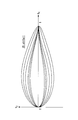
- the wind turbine blade 1 is a three-dimensional blade, and extends from the blade root side 1a, which is the rotation center side, toward the blade tip side 1b.
- the radial position (corresponding to the distance from the rotation center of the blade) of each blade thickness ratio (percentage of the maximum blade thickness divided by the cord length) Z (the longitudinal axis direction of the blade) at the position of the blade) represented by using a blade element section cut by a constant section.
- FIG. 1 shows that blade element cross sections cut at radial positions with blade thickness ratios of 18%, 21%, 24%, 30%, 36%, and 42% are used as the definition of the shape of the wind turbine blade. ing.
- a radial position r corresponding to the distance from the rotation center of the blade (or a dimensionless radial position r / R obtained by dividing the radial position by the blade radius). ) May be used.
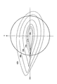
- FIG. 2 the blade element cross section of FIG. 1 is projected onto the XY plane (a plane perpendicular to the Z axis).
- the right side is the blade leading edge and the left side is the blade trailing edge.
- the wind turbine blade has a shape in which the cord length decreases from the blade root side to the blade tip side.
- the shape shown in the figure is called an airfoil.
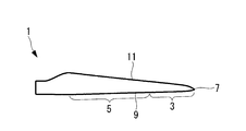
- the dimensionless radial position r / R obtained by dividing the radial position r by the blade radius R (1/2 of the blade diameter) is 0.6 or more and 1.0 or less.
- the maximum blade thickness position in the blade cross section of the blade tip region 5 is located closer to the blade leading edge 9 than the maximum blade thickness position in the blade cross section of the blade body side region 7.
- each blade cross section shown in FIG. 5 when the cord length position of the blade leading edge is 0% cord length and the cord length position of the blade trailing edge is 100% cord length, the blade root side From the blade tip side to the blade tip side, the maximum blade thickness position is displaced (shifted) from the 40% cord length to the blade leading edge side, such as 36% cord length, 30% cord length, 24% cord length, 20% cord length, etc. is doing.
- line segment L1 has shown the largest blade
- the maximum blade thickness position in the blade main body side region 5 is 40% cord length or more. As shown in the figure, it is preferable that the maximum blade thickness position is gradually displaced toward the blade leading edge 9 toward the blade tip 7 (see FIG. 4).
- the maximum blade thickness position in the blade tip region 3 is a region where the dimensionless radius position is 0.6 or more and 0.9 or less, and is 25% code length or more and 40% code length or less, and the dimensionless radius position is 1 0 (ie, the position of the blade tip 7), the length is 10% or more and 30% or less. More preferably, the maximum blade thickness position in the blade tip region 3 is a region where the dimensionless radius position is 0.7 or more and 0.85 or less, and is 26% code length or more and 36% code length or less, and the dimensionless radius position is At a position set to 1.0, the code length is 20% code length or more and 30% code length or less.
- the airfoil has 0 camber. This facilitates manufacture even on the blade tip side where it is difficult to manufacture a complicated shape with a thin blade thickness.
- the camber gradually approaches 0 toward the blade tip 7 so that the camber becomes 0 at the blade tip 7.
- FIGS. 6 to 8 show the results of numerical simulation of the airfoil when the maximum blade thickness position is changed from 24% code length to 36% code length.
- the numerical simulation conditions were a design peripheral speed ratio of 8.0 to 8.5 and a Reynolds number of 3 million to 10 million.
- the design lift coefficient and the maximum lift-drag ratio are obtained. It can be seen that the aerodynamic performance is improved by increasing the noise and the noise is reduced by reducing the boundary layer thickness (exclusion thickness).
- the design lift coefficient and the maximum lift-drag ratio increase as the maximum blade thickness position is closer to the blade leading edge 9 side. It was found that the aerodynamic performance was improved and the noise was reduced by reducing the boundary layer thickness (exclusion thickness).
- the maximum blade thickness position is arranged on the blade leading edge 9 side, the blade trailing edge 11 is relatively thin, and the strength of the blade trailing edge 11 against the edge moment generated by the load applied to the wind turbine blade 1 is increased. May decrease.
- the edge moment on the blade tip 7 side is smaller than that on the blade root side, and the strength near the blade trailing edge 11 is high even if the maximum blade thickness position is arranged on the blade leading edge 9 side. Focused on not becoming a big problem. Therefore, in the present embodiment, the maximum blade thickness position of the blade tip region 3 is positioned closer to the blade leading edge 9 than the maximum blade thickness position of the blade body side region 5. As a result, the aerodynamic performance of the blade tip region 3 can be improved, and aerodynamic noise in the blade tip region, which has the largest peripheral speed and is the main cause of noise, can be effectively reduced.
- the aerodynamic performance can be improved by increasing the design lift coefficient and the maximum lift / drag ratio.
- the aerodynamic noise can be effectively reduced toward the blade tip 7 side where the peripheral speed increases and the noise increases.
- the present embodiment is provided for a wind turbine generator including a rotor connected to the blade root side of the wind turbine blade and rotated by the wind turbine blade, and a generator that converts the rotational force obtained by the rotor into an electrical output.
- the maximum blade thickness line formed by connecting the maximum blade thickness position in the blade cross section at each radial position in the blade radial direction is the blade leading edge 9 of the blade tip region 3 compared to the first embodiment.
- the points to be optimized differ depending on the shape of the blade, and the other points, that is, the point where the maximum blade thickness position in the blade tip region is positioned closer to the blade leading edge side than the maximum blade thickness position in the blade body side region are the same. Accordingly, differences will be described below, and description of similar points will be omitted.
- FIG. 9 shows the maximum blade thickness position at each radial position of the wind turbine blade according to the present embodiment.
- a line segment L2 in the figure indicates the maximum blade thickness position.
- the maximum blade thickness position is arranged at the same angular position when viewed from the blade rotation center at each radial position. As shown in the figure, this is realized by displacing the blade leading edge 9 toward the blade trailing edge 11 toward the blade tip side.
- the maximum blade thickness line formed by connecting the maximum blade thickness positions in the blade cross section at each radial position in the radial direction is arranged so as to be substantially linear in the radial direction of the wind turbine blade.
- FIG. 10 shows a maximum blade thickness line 13 that is substantially linear by displacing the blade leading edge 9 toward the blade trailing edge 11 as shown in FIG.
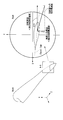
- the blade leading edge 9 in the blade tip region 3 is largely displaced toward the blade trailing edge 11 in the transition region 15 where the blade main body side region 5 transitions to the blade tip region 3 as shown in FIG.
- the blade is gradually displaced toward the blade leading edge 7 in the connection region 16 connected to the region 15, and finally connected to the blade tip 7 in the terminal region 17 connected to the connection region 16. It is a so-called S-shape that is displaced toward the trailing edge 11.
- the maximum blade thickness line 13 in a substantially straight line shape in the radial direction, the following effects are obtained.
- a girder that mainly bears the strength of the wind turbine blade extends in the radial direction.
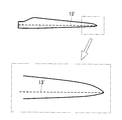
- the maximum blade thickness line 13 ′ is formed linearly in the radial direction. It is because manufacture becomes easy by setting it as a linear girder.
- the maximum blade thickness position in the blade tip region is the same as that in the blade main body side region.
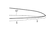
- the maximum blade thickness position of the blade tip region 3 when the maximum blade thickness position of the blade tip region 3 is positioned closer to the blade leading edge 9 than the maximum blade thickness position of the blade main body side region 5, FIG. If the same blade leading edge shape and blade trailing edge shape are to be adopted, the maximum blade thickness line 13 ′′ cannot maintain a linear shape in the blade tip region 3 as shown in FIG. End up.
- the maximum blade thickness line 13 is made substantially linear by displacing the blade leading edge 9 toward the blade trailing edge 11 (see FIG. 10).
- a substantially linear girder can be adopted, and the manufacture becomes easy.
- the receptor serving as the lightning strike point is disposed at the maximum blade thickness position, the receptor can be disposed in a substantially straight line, which facilitates manufacture.
- the blade leading edge 9 in the blade tip region 3 when the blade leading edge 9 in the blade tip region 3 is displaced toward the blade trailing edge 11 as in the present embodiment (particularly, the blade leading edge 9 has an S-shape).
- the wing trailing edge 11 can be rounded and have a larger curvature (see region 19 in the figure). Thereby, the phase of the aerodynamic noise generated from the blade trailing edge 11 in the blade tip region 3 can be shifted in the blade radial direction, and noise can be further reduced.
- the design peripheral speed ratio is set to 8.0 or more and 8.5 or less, but the present invention is not limited to this.
- the design peripheral speed ratio is 6.0 or more and 9.0 or less. Can also be applied.
Landscapes
- Engineering & Computer Science (AREA)
- Physics & Mathematics (AREA)
- Fluid Mechanics (AREA)
- Life Sciences & Earth Sciences (AREA)
- Sustainable Development (AREA)
- Sustainable Energy (AREA)
- Chemical & Material Sciences (AREA)
- Combustion & Propulsion (AREA)
- Mechanical Engineering (AREA)
- General Engineering & Computer Science (AREA)
- Wind Motors (AREA)
Abstract
L'invention porte sur une pale de turbine éolienne qui peut améliorer la performance aérodynamique de la région d'extrémité de pointe de la pale et qui peut aussi réduire le bruit aérodynamique. La pale de turbine éolienne comprend un corps principal de pale dans lequel la longueur de la corde décroît du côté du pied de la pale vers le côté d'extrémité de pointe de la pale. Le corps principal de pale comprend : une zone d'extrémité de pointe de pale dans laquelle la position radiale sans dimension qui est obtenue en divisant la position radiale par le rayon de la pale (1/2 du diamètre de la pale) est de 0,6 à 1,0 inclus ; et une zone du côté corps principal dans laquelle la position radiale sans dimension est inférieure à 0,6. La position de l'épaisseur maximum de pale (L1), dans la section transversale de la pale de la zone d'extrémité de pointe de la pale est située plus vers le côté du bord d'attaque (9) de la pale que la position de l'épaisseur maximum de pale (L1) dans la section transversale de la pale dans la zone du côté corps principal.
Priority Applications (3)
| Application Number | Priority Date | Filing Date | Title |
|---|---|---|---|
| EP12752158.1A EP2682602B1 (fr) | 2011-02-28 | 2012-02-24 | Pale de turbine éolienne et générateur d'électricité éolienne équipé de cette pale |
| KR1020137022010A KR20130107370A (ko) | 2011-02-28 | 2012-02-24 | 풍차 날개 및 이것을 구비한 풍력 발전 장치 |
| US13/468,205 US8801387B2 (en) | 2011-02-28 | 2012-05-10 | Wind turbine blade and wind turbine generator including the same |
Applications Claiming Priority (2)
| Application Number | Priority Date | Filing Date | Title |
|---|---|---|---|
| JP2011-043189 | 2011-02-28 | ||
| JP2011043189A JP5479388B2 (ja) | 2011-02-28 | 2011-02-28 | 風車翼およびこれを備えた風力発電装置 |
Related Child Applications (1)
| Application Number | Title | Priority Date | Filing Date |
|---|---|---|---|
| US13/468,205 Continuation US8801387B2 (en) | 2011-02-28 | 2012-05-10 | Wind turbine blade and wind turbine generator including the same |
Publications (1)
| Publication Number | Publication Date |
|---|---|
| WO2012117979A1 true WO2012117979A1 (fr) | 2012-09-07 |
Family
ID=46757916
Family Applications (1)
| Application Number | Title | Priority Date | Filing Date |
|---|---|---|---|
| PCT/JP2012/054664 Ceased WO2012117979A1 (fr) | 2011-02-28 | 2012-02-24 | Pale de turbine éolienne et générateur d'électricité éolienne équipé de cette pale |
Country Status (5)
| Country | Link |
|---|---|
| US (1) | US8801387B2 (fr) |
| EP (1) | EP2682602B1 (fr) |
| JP (1) | JP5479388B2 (fr) |
| KR (1) | KR20130107370A (fr) |
| WO (1) | WO2012117979A1 (fr) |
Families Citing this family (17)
| Publication number | Priority date | Publication date | Assignee | Title |
|---|---|---|---|---|
| ES2966169T3 (es) * | 2010-07-16 | 2024-04-18 | Lm Wind Power As | Pala de turbina eólica con hombro estrecho y perfiles de perfil alar relativamente gruesos |
| CN104929866B (zh) * | 2010-10-22 | 2018-05-22 | 三菱重工业株式会社 | 风车翼及具备该风车翼的风力发电装置以及风车翼的设计方法 |
| GB201109412D0 (en) * | 2011-06-03 | 2011-07-20 | Blade Dynamics Ltd | A wind turbine rotor |
| DE102012206109C5 (de) * | 2012-04-13 | 2022-06-09 | Wobben Properties Gmbh | Rotorblatt einer Windenergieanlage |
| JP5995816B2 (ja) * | 2013-10-18 | 2016-09-21 | 三菱重工業株式会社 | 風車翼及び風力発電装置 |
| WO2015145723A1 (fr) * | 2014-03-28 | 2015-10-01 | 中国電力株式会社 | Pale de turbine éolienne et générateur d'énergie éolienne la comportant |
| DE102015012427A1 (de) * | 2015-09-25 | 2017-03-30 | Senvion Gmbh | Rotorblatt mit einem schalloptimierten Profil sowie Verfahren zum Herstellen eines Rotorblatts |
| DK3488101T3 (da) * | 2016-08-30 | 2023-05-01 | Siemens Gamesa Renewable Energy As | Strømningsregulerende indretning til en vindmøllerotorvinge |
| JP6783212B2 (ja) * | 2017-10-20 | 2020-11-11 | 三菱重工業株式会社 | 風車翼へのボルテックスジェネレータの配置位置決定方法、風車翼アセンブリの製造方法及び風車翼アセンブリ |
| DE102017124861A1 (de) | 2017-10-24 | 2019-04-25 | Wobben Properties Gmbh | Rotorblatt einer Windenergieanlage und Verfahren zu dessen Auslegung |
| US11781522B2 (en) | 2018-09-17 | 2023-10-10 | General Electric Company | Wind turbine rotor blade assembly for reduced noise |
| DE102019119027B4 (de) * | 2019-07-12 | 2022-04-28 | Wobben Properties Gmbh | Rotorblatt und Windenergieanlage |
| US12292027B2 (en) * | 2020-06-29 | 2025-05-06 | Vestas Wind Systems A/S | Wind turbine with particular combined radius specific solidities along the rotor radius |
| ES3053844T3 (en) * | 2020-12-17 | 2026-01-27 | Vestas Wind Sys As | A pitch controlled wind turbine with blade connecting members |
| US12173684B1 (en) | 2024-03-19 | 2024-12-24 | King Fahd University Of Petroleum And Minerals | Wind turbine for a region with low wind speed |
| EP4628724A1 (fr) | 2024-04-04 | 2025-10-08 | Nordex Energy SE & Co. KG | Une pale de rotor d'éolienne avec une section d'extrémité |
| EP4656871A1 (fr) | 2024-05-28 | 2025-12-03 | Nordex Energy SE & Co. KG | Une pale de rotor d'éolienne |
Citations (4)
| Publication number | Priority date | Publication date | Assignee | Title |
|---|---|---|---|---|
| US5474425A (en) * | 1992-03-18 | 1995-12-12 | Advanced Wind Turbines, Inc. | Wind turbine rotor blade |
| EP1152148A1 (fr) | 2000-05-01 | 2001-11-07 | Enron Wind Energy Systems Co. | Profils de pale pour éoliennes |
| JP2005533210A (ja) * | 2002-06-05 | 2005-11-04 | アロイス・ヴォベン | 風力発電装置のローターブレード |
| JP3935804B2 (ja) * | 2002-08-26 | 2007-06-27 | 三菱重工業株式会社 | 翼及びこれを備える風力発電装置 |
Family Cites Families (8)
| Publication number | Priority date | Publication date | Assignee | Title |
|---|---|---|---|---|
| US2709052A (en) * | 1952-04-15 | 1955-05-24 | Charles J Fletcher | Spanwise flow control of fluid swept lifting surfaces |
| US4976587A (en) * | 1988-07-20 | 1990-12-11 | Dwr Wind Technologies Inc. | Composite wind turbine rotor blade and method for making same |
| JP4024208B2 (ja) * | 2001-09-17 | 2007-12-19 | クリーン カーレント パワー システムズ インコーポレイテッド | 水中用ダクテッドタービン |
| JP3368537B1 (ja) * | 2001-11-08 | 2003-01-20 | 学校法人東海大学 | 直線翼型風水車 |
| DE10319246A1 (de) * | 2003-04-28 | 2004-12-16 | Aloys Wobben | Rotorblatt einer Windenergieanlage |
| CN101263277B (zh) | 2005-07-15 | 2011-11-30 | 维斯塔斯风力系统有限公司 | 风轮机叶片 |
| US7789629B2 (en) * | 2006-12-07 | 2010-09-07 | Verdant Power | Non-fouling kinetic hydro power system axial-flow blade tip treatment |
| DE102008052858B9 (de) * | 2008-10-23 | 2014-06-12 | Senvion Se | Profil eines Rotorblatts und Rotorblatt einer Windenergieanlage |
-
2011
- 2011-02-28 JP JP2011043189A patent/JP5479388B2/ja active Active
-
2012
- 2012-02-24 WO PCT/JP2012/054664 patent/WO2012117979A1/fr not_active Ceased
- 2012-02-24 KR KR1020137022010A patent/KR20130107370A/ko not_active Ceased
- 2012-02-24 EP EP12752158.1A patent/EP2682602B1/fr active Active
- 2012-05-10 US US13/468,205 patent/US8801387B2/en active Active
Patent Citations (4)
| Publication number | Priority date | Publication date | Assignee | Title |
|---|---|---|---|---|
| US5474425A (en) * | 1992-03-18 | 1995-12-12 | Advanced Wind Turbines, Inc. | Wind turbine rotor blade |
| EP1152148A1 (fr) | 2000-05-01 | 2001-11-07 | Enron Wind Energy Systems Co. | Profils de pale pour éoliennes |
| JP2005533210A (ja) * | 2002-06-05 | 2005-11-04 | アロイス・ヴォベン | 風力発電装置のローターブレード |
| JP3935804B2 (ja) * | 2002-08-26 | 2007-06-27 | 三菱重工業株式会社 | 翼及びこれを備える風力発電装置 |
Non-Patent Citations (2)
| Title |
|---|
| "Wind Energy Handbook", JOHN WILEY & SONS, pages: 378 |
| See also references of EP2682602A4 |
Also Published As
| Publication number | Publication date |
|---|---|
| JP5479388B2 (ja) | 2014-04-23 |
| US8801387B2 (en) | 2014-08-12 |
| KR20130107370A (ko) | 2013-10-01 |
| EP2682602A4 (fr) | 2014-04-02 |
| JP2012180771A (ja) | 2012-09-20 |
| EP2682602A1 (fr) | 2014-01-08 |
| US20120280509A1 (en) | 2012-11-08 |
| EP2682602B1 (fr) | 2015-06-10 |
Similar Documents
| Publication | Publication Date | Title |
|---|---|---|
| JP5479388B2 (ja) | 風車翼およびこれを備えた風力発電装置 | |
| US8932024B2 (en) | Wind turbine blade and wind power generator using the same | |
| EP3037656B1 (fr) | Pale de rotor à générateurs de vortex | |
| US20150132141A1 (en) | Rotor blade of a wind turbine | |
| US20120217754A1 (en) | Wind turbine blade, wind turbine generator with the same, and design method of wind turbine blade | |
| EP3453872B1 (fr) | Procédés permettant d'atténuer le bruit pendant des conditions de vitesse du vent élevée d'éoliennes | |
| US8936435B2 (en) | System and method for root loss reduction in wind turbine blades | |
| US20100166556A1 (en) | Partial arc shroud for wind turbine blades | |
| US8851857B2 (en) | Wind turbine blade and wind power generator using the same | |
| EP2863052B1 (fr) | Rotor de turbine éolienne et éolienne | |
| US11028823B2 (en) | Wind turbine blade with tip end serrations | |
| CN116157597A (zh) | 风力涡轮机 | |
| JP5433554B2 (ja) | 風車翼およびこれを備えた風力発電装置ならびに風車翼の設計方法 | |
| CN112689710A (zh) | 用于降低噪声的风力涡轮转子叶片组件 | |
| JP5479300B2 (ja) | 風車翼およびこれを備えた風力発電装置ならびに風車翼の設計方法 | |
| JP5675270B2 (ja) | 風車翼およびこれを備えた風力発電装置ならびに風車翼の設計方法 | |
| JP5574915B2 (ja) | 風車翼およびこれを備えた風力発電装置ならびに風車翼の設計方法 | |
| JP5433553B2 (ja) | 風車翼およびこれを備えた風力発電装置ならびに風車翼の設計方法 | |
| JP5574914B2 (ja) | 風車翼およびこれを備えた風力発電装置ならびに風車翼の設計方法 | |
| US20200063709A1 (en) | Rotor Blade Assembly Having Twist, Chord, and Thickness Distribution for Improved Performance |
Legal Events
| Date | Code | Title | Description |
|---|---|---|---|
| 121 | Ep: the epo has been informed by wipo that ep was designated in this application |
Ref document number: 12752158 Country of ref document: EP Kind code of ref document: A1 |
|
| ENP | Entry into the national phase |
Ref document number: 20137022010 Country of ref document: KR Kind code of ref document: A |
|
| WWE | Wipo information: entry into national phase |
Ref document number: 2012752158 Country of ref document: EP |
|
| NENP | Non-entry into the national phase |
Ref country code: DE |