EP2682677A1 - Wärmetauscher - Google Patents
Wärmetauscher Download PDFInfo
- Publication number
- EP2682677A1 EP2682677A1 EP11859815.0A EP11859815A EP2682677A1 EP 2682677 A1 EP2682677 A1 EP 2682677A1 EP 11859815 A EP11859815 A EP 11859815A EP 2682677 A1 EP2682677 A1 EP 2682677A1
- Authority
- EP
- European Patent Office
- Prior art keywords
- transfer tube
- heat transfer
- bundle
- heat
- heat exchanger
- Prior art date
- Legal status (The legal status is an assumption and is not a legal conclusion. Google has not performed a legal analysis and makes no representation as to the accuracy of the status listed.)
- Granted
Links
Images



Classifications
-
- F—MECHANICAL ENGINEERING; LIGHTING; HEATING; WEAPONS; BLASTING
- F23—COMBUSTION APPARATUS; COMBUSTION PROCESSES
- F23J—REMOVAL OR TREATMENT OF COMBUSTION PRODUCTS OR COMBUSTION RESIDUES; FLUES
- F23J15/00—Arrangements of devices for treating smoke or fumes
- F23J15/06—Arrangements of devices for treating smoke or fumes of coolers
-
- F—MECHANICAL ENGINEERING; LIGHTING; HEATING; WEAPONS; BLASTING
- F28—HEAT EXCHANGE IN GENERAL
- F28F—DETAILS OF HEAT-EXCHANGE AND HEAT-TRANSFER APPARATUS, OF GENERAL APPLICATION
- F28F1/00—Tubular elements; Assemblies of tubular elements
-
- F—MECHANICAL ENGINEERING; LIGHTING; HEATING; WEAPONS; BLASTING
- F23—COMBUSTION APPARATUS; COMBUSTION PROCESSES
- F23J—REMOVAL OR TREATMENT OF COMBUSTION PRODUCTS OR COMBUSTION RESIDUES; FLUES
- F23J15/00—Arrangements of devices for treating smoke or fumes
- F23J15/08—Arrangements of devices for treating smoke or fumes of heaters
-
- F—MECHANICAL ENGINEERING; LIGHTING; HEATING; WEAPONS; BLASTING
- F28—HEAT EXCHANGE IN GENERAL
- F28D—HEAT-EXCHANGE APPARATUS, NOT PROVIDED FOR IN ANOTHER SUBCLASS, IN WHICH THE HEAT-EXCHANGE MEDIA DO NOT COME INTO DIRECT CONTACT
- F28D21/00—Heat-exchange apparatus not covered by any of the groups F28D1/00 - F28D20/00
- F28D21/0001—Recuperative heat exchangers
- F28D21/0003—Recuperative heat exchangers the heat being recuperated from exhaust gases
- F28D21/001—Recuperative heat exchangers the heat being recuperated from exhaust gases for thermal power plants or industrial processes
-
- F—MECHANICAL ENGINEERING; LIGHTING; HEATING; WEAPONS; BLASTING
- F28—HEAT EXCHANGE IN GENERAL
- F28D—HEAT-EXCHANGE APPARATUS, NOT PROVIDED FOR IN ANOTHER SUBCLASS, IN WHICH THE HEAT-EXCHANGE MEDIA DO NOT COME INTO DIRECT CONTACT
- F28D7/00—Heat-exchange apparatus having stationary tubular conduit assemblies for both heat-exchange media, the media being in contact with different sides of a conduit wall
- F28D7/16—Heat-exchange apparatus having stationary tubular conduit assemblies for both heat-exchange media, the media being in contact with different sides of a conduit wall the conduits being arranged in parallel spaced relation
- F28D7/1615—Heat-exchange apparatus having stationary tubular conduit assemblies for both heat-exchange media, the media being in contact with different sides of a conduit wall the conduits being arranged in parallel spaced relation the conduits being inside a casing and extending at an angle to the longitudinal axis of the casing; the conduits crossing the conduit for the other heat exchange medium
-
- F—MECHANICAL ENGINEERING; LIGHTING; HEATING; WEAPONS; BLASTING
- F28—HEAT EXCHANGE IN GENERAL
- F28G—CLEANING OF INTERNAL OR EXTERNAL SURFACES OF HEAT-EXCHANGE OR HEAT-TRANSFER CONDUITS, e.g. WATER TUBES OR BOILERS
- F28G15/00—Details
-
- B—PERFORMING OPERATIONS; TRANSPORTING
- B01—PHYSICAL OR CHEMICAL PROCESSES OR APPARATUS IN GENERAL
- B01D—SEPARATION
- B01D53/00—Separation of gases or vapours; Recovering vapours of volatile solvents from gases; Chemical or biological purification of waste gases, e.g. engine exhaust gases, smoke, fumes, flue gases, aerosols
- B01D53/34—Chemical or biological purification of waste gases
- B01D53/46—Removing components of defined structure
- B01D53/48—Sulfur compounds
- B01D53/50—Sulfur oxides
-
- B—PERFORMING OPERATIONS; TRANSPORTING
- B01—PHYSICAL OR CHEMICAL PROCESSES OR APPARATUS IN GENERAL
- B01D—SEPARATION
- B01D53/00—Separation of gases or vapours; Recovering vapours of volatile solvents from gases; Chemical or biological purification of waste gases, e.g. engine exhaust gases, smoke, fumes, flue gases, aerosols
- B01D53/34—Chemical or biological purification of waste gases
- B01D53/74—General processes for purification of waste gases; Apparatus or devices specially adapted therefor
- B01D53/86—Catalytic processes
- B01D53/8621—Removing nitrogen compounds
- B01D53/8625—Nitrogen oxides
-
- F—MECHANICAL ENGINEERING; LIGHTING; HEATING; WEAPONS; BLASTING
- F28—HEAT EXCHANGE IN GENERAL
- F28F—DETAILS OF HEAT-EXCHANGE AND HEAT-TRANSFER APPARATUS, OF GENERAL APPLICATION
- F28F2280/00—Mounting arrangements; Arrangements for facilitating assembling or disassembling of heat exchanger parts
-
- F—MECHANICAL ENGINEERING; LIGHTING; HEATING; WEAPONS; BLASTING
- F28—HEAT EXCHANGE IN GENERAL
- F28F—DETAILS OF HEAT-EXCHANGE AND HEAT-TRANSFER APPARATUS, OF GENERAL APPLICATION
- F28F2280/00—Mounting arrangements; Arrangements for facilitating assembling or disassembling of heat exchanger parts
- F28F2280/02—Removable elements
-
- Y—GENERAL TAGGING OF NEW TECHNOLOGICAL DEVELOPMENTS; GENERAL TAGGING OF CROSS-SECTIONAL TECHNOLOGIES SPANNING OVER SEVERAL SECTIONS OF THE IPC; TECHNICAL SUBJECTS COVERED BY FORMER USPC CROSS-REFERENCE ART COLLECTIONS [XRACs] AND DIGESTS
- Y02—TECHNOLOGIES OR APPLICATIONS FOR MITIGATION OR ADAPTATION AGAINST CLIMATE CHANGE
- Y02E—REDUCTION OF GREENHOUSE GAS [GHG] EMISSIONS, RELATED TO ENERGY GENERATION, TRANSMISSION OR DISTRIBUTION
- Y02E20/00—Combustion technologies with mitigation potential
- Y02E20/30—Technologies for a more efficient combustion or heat usage
Definitions
- the present invention relates to a heat exchanger in an air pollution control system.
- an air pollution control apparatus of a boiler for thermal power plant or chemical plant is disposed in order of denitrification equipment in a flue gas flow channel, an air-preheater air heater, a heat recovery unit of reheating gas-gas heater, a dry electronic precipitator, wet desulfurization equipment, a reheating unit for the gas-gas heater, and a chimney.
- the gas-gas heater is configured such that the heat recovery unit and the reheating unit are connected to a cool and hot water circulating line to perform a heat exchange with a flue gas through a circulating pump using water as a medium.
- the flue gas of the boiler is guided to the air heater to be cooled to a temperature of, for example, 130 to 150°C by exchanging heat with combustion air and then is guided to the heat recovery unit of the gas-gas heater to be further cooled. Thereafter, after the flue gas is guided to the electronic precipitator to remove fly ashes, a high-temperature flue gas in an outlet of the electronic precipitator is further cooled to a low temperature by exchanging heat with water and then is guided to the wet desulfurization equipment.
- SO 2 contained in the flue gas is absorbed and removed by absorbent which is prepared by dissolving, for example, limestone in the form of slurry and remaining fly ashes in the flue gas are also removed in the gas-solution contact process. Then, the flue gas in which SO 2 and the fly ashes are removed is guided to the reheating unit of the gas-gas heater.
- the temperature of the flue gas temperature-dropped by SO 2 absorbent and the like in the treatment process of the wet desulfurization equipment is raised by the heat exchange with heat medium water passing through an interior of a pipe disposed in the reheating unit of the gas-gas heater. This causes functions of preventing white smoke generation due to a reduction of the amount of water condensation and improving diffusion efficiency due to temperature rise, when the flue gas is released from the chimney to an atmosphere.
- a fin tube heat exchanger has been proposed as a heat exchange method of large-scaled heat recovery unit and reheating unit of the gas-gas heater in coal-fired power plant (Patent Literature 1).
- Patent Literature 1 Japanese Laid-open Patent Publication No. 11-304138
- the present invention has been achieved to solve the above problems, and an object of the present invention is to provide a heat exchanger that can draw out only a specific heat transfer tube bundle to improve work efficiency.
- a heat exchanger including: a heat transfer tube bundle housing duct for housing heat transfer tube bundles; openings provided on a sidewall of the heat transfer tube bundle housing duct, for freely inserting and removing the heat transfer tube bundles; and rails provided in a direction perpendicular to an inflowing direction of a flue gas within the heat transfer tube bundle housing duct, for freely moving the heat transfer tube bundles.
- the heat exchanger including: bundle-bottom-rails provided in the openings, for drawing out and moving the heat transfer tube bundles from a sidewall side in a direction perpendicular to a flue gas direction within the heat transfer tube bundle housing duct.
- the heat exchanger according to the first aspect, further including: temporary support parts provided in a structure outside the heat transfer tube bundle housing duct; moving rails supported by the temporary support parts, for moving the heat transfer tube bundles; and a driving apparatus for drawing out the heat transfer tube bundles on the moving rails.
- the heat exchanger including: bundle-bottom-rail provided in the openings, for drawing out and moving the heat transfer tube bundles from the sidewall side in a direction perpendicular to a flue gas direction within the heat transfer tube bundle housing duct.
- the heat exchanger according to the fourth aspect including: back rails provided at back sides of the heat transfer tube bundles, the back side coming in contact with the bundle-bottom-rail.
- FIG. 6 is a schematic view of an air pollution control system to which heat exchangers according to the present embodiment are applied.
- an air pollution control system 100 removes nitride oxide (NOx), soot dust, and sulfur oxide (SOx) contained in the flue gas.
- a flue gas G 0 discharged from the boiler 101 is introduced into denitrification equipment 102 filled with a catalyst.
- the nitrogen oxide contained in the flue gas G 0 is reduced to water and nitrogen by ammonia (NH 3 ) injected as a reducing agent to become harmless.
- a flue gas G 1 discharged from the denitrification equipment 102 is generally cooled to the temperature of 130°C to 150°C through an air heater (AH) 103.
- AH air heater
- a flue gas G 2 passed through the air heater 103 is introduced into a heat recovery unit 104 serving as a heat exchanger of gas-gas heater and then is heat-recovered by a heat exchange with a heat medium (for example, water).
- a temperature of a flue gas G 3 passed through the heat recovery unit 104 becomes approximately 85°C to 110°C to improve dust-collecting capability of an electronic precipitator (EP) 105, for example.
- EP electronic precipitator
- the flue gas G 3 passed through the heat recovery unit 104 is introduced into the electronic precipitator 105 and then the shoot dust therein is removed.
- a flue gas G 4 passed through the electronic precipitator 105 is pressurized by an air blower 106 to be driven by an electric motor.
- the air blower 106 may not be provided, or may be disposed on a downstream side of a reheating unit 108 of the gas-gas heater.
- a flue gas G 5 pressurized by the air blower 106 is introduced into desulfurization equipment 107.
- the sulfur oxide contained in the flue gas G 5 is absorbed and removed by an absorbent which is prepared by dissolving limestone in a form of slurry, and gypsum (not illustrated) is produced as a byproduct.
- the temperature of a flue gas G 6 passed through the desulfurization equipment 107 is generally decreased to the extent of about 50°C.
- the flue gas G 6 passed through the desulfurization equipment 107 is introduced into the reheating unit 108 serving as the heat exchanger of the gas-gas heater.
- the reheating unit 108 heats the flue gas G 6 by recovery heat which is recovered by the heat recovery unit 104.
- the flue gas G 6 which has the temperature of about 50°C, at an outlet of the desulfurization equipment 107 is reheated to about 85°C to 110°C with the reheating unit 108, and then is released as a flue gas G 8 from the chimney 111 to an atmosphere.
- FIG. 7 is a schematic view of a heat exchanger of an air pollution control installation.
- the heat exchanger into which the flue gas G 2 is introduced to exchange heat with the heat medium 83 is provided.
- the heat exchanger has the circulating pipe 110 for circulating the heat medium 83 between the heat recovery unit 104 and the reheating unit 108.
- the heat medium 83 is circulated between the heat recovery unit 104 and the reheating unit 108 through the circulating pipe 110.
- a surface of the heat medium circulating passage 110 provided in each of the heat recovery unit 104 and the reheating unit 108 is provided with a heat transfer tube 11 on which a plurality of fins are provided.
- a heat exchanging unit 86 is provided in the heat medium circulating passage 110 to compensate energy, which is equivalent to temperature drop absorbed by radiant heat when the heat medium 83 is circulated, by heating with a steam 87 and to be capable of maintaining and adjusting a medium temperature of the heat medium 83.
- the heat medium 83 is supplied to the heat medium circulating passage 110 from a heat medium tank 88.
- the heat medium 83 is circulated in the circulating passage 110 by the heat medium circulating pump 109.
- a supply quantity of the steam 87 is adjusted by an adjusting valve V 1 according to the gas temperature of the purified gas G 6 from the desulfurization equipment 107
- the heat medium 83 to be fed into the reheating unit 108 is supplied to the heat recovery unit 104 by an adjusting valve V 2 according to the gas temperature of the flue gas G 3 discharged from the heat recovery unit 104, and thus a supply quantity of the heat medium 83 to be fed into the reheating unit 108 is adjusted.
- the purified gas G 7 discharged from the reheating unit 108 is discharged from the chimney 111 to the outside.
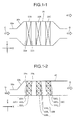
- FIGS. 1-1 and 1-2 are a schematic view of the heat exchanger, respectively.
- the heat exchanger includes a heat transfer tube bundle housing duct 20 in which a plurality of heat transfer tube bundles, that is, a high-temperature heat transfer tube bundle 22A, a middle-temperature heat transfer tube bundle 22B, and a low-temperature heat transfer tube bundle 22C are disposed from an upstream side in an inflowing direction of the flue gas, the heat transfer tube bundles being an aggregation which binds together the heat transfer tube bundles.
- the plurality of heat transfer tube bundles 22A (22A 1 to 22A 3 ), 22B (22B 1 to 22B 3 ), and 22C (22C 1 to 22C 3 ) are disposed with a predetermined interval to perform the heat recovery or the heat exchange in a gas flowing direction of the flue gas.
- the flue gas G, a duct inlet part 20a, and an expanded part 20b are illustrated.
- an upstream side in a flue gas introducing direction of the heat transfer tube bundle is a front 22a
- a downstream side in the flue gas introducing direction is a rear 22b.
- an X-direction is the flue gas flowing direction
- a Y-direction is an insertion direction of the heat transfer tube bundle
- a Z-direction is a stacked installation direction of the heat transfer tube bundle.
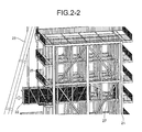
- FIGS. 2-1 and 2-2 are perspective views illustrating schematically an exterior of the heat exchanger according to the first embodiment.
- the heat exchanger includes the heat transfer tube bundle housing duct (hereinafter, referred to as a "bundle housing duct") 20 which houses heat transfer tube bundles 22, openings 26 which are provided on a sidewall of the heat transfer tube bundle housing duct 20 to freely insert and remove the heat transfer tube bundles 22, and bottom rails 27 which are provided in a direction perpendicular to the inflowing direction of the flue gas G within the bundle housing duct 20 to freely move the heat transfer tube bundles.
- a "bundle housing duct” 20 which houses heat transfer tube bundles 22, openings 26 which are provided on a sidewall of the heat transfer tube bundle housing duct 20 to freely insert and remove the heat transfer tube bundles 22, and bottom rails 27 which are provided in a direction perpendicular to the inflowing direction of the flue gas G within the bundle housing duct 20 to freely move the heat transfer tube bundles.
- a reference numeral 25 indicates a handrail provided in a framework stage through which persons come and go.
- the handrail 25 is vertically stood so that persons do not fall down, but is configured such that the bundles can pass through, as illustrated in FIG. 2-1 , since the handrail 25 is provided with a hinge which is movable so as to recline in a horizontal position at the time of taking the heat transfer tube bundles 22 in and out.
- a floor 25a of the handrail is configured so as to temporarily place the heat transfer tube bundles 22 when the handrail 25 is reclined.
- the X-direction is the flue gas flowing direction
- the Y-direction is the insertion direction of the heat transfer tube bundle
- the Z-direction is the stacked installation direction of the heat transfer tube bundle.
- the heat transfer tube bundle 20 is set to be drawn out in following manners.
- the bundle-bottom-rail 27 is installed at a position corresponding to a lower part of each bundle in a longitudinal direction inside the duct from a sidewall side to draw out and move the bundle toward the opening, the heat transfer tube bundle is easily drawn out in the longitudinal direction toward the opening of the sidewall on the bundle-bottom-rail 27.
- the heat transfer tube bundle loaded on the bundle-bottom-rail 27 is drawn out in the longitudinal direction by, for example, a chain block.
- module bundles ranging from, for example, 20 to 30 tons per one bundle are lifted one by one in turns from an upper-stage bundle by the crane from the opening installed at an upper part of the bundle housing duct for storing the bundle of the heat exchanger, while the present invention can shorten time of about 40% with respect to replacement work of the bundle ranging generally from 20 to 30 tons per one because of drawing out only the specified heat transfer tube bundle.
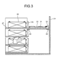
- FIG. 3 is a schematic view of a heat exchanger according to a second embodiment.
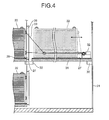
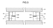
- FIGS. 4 and 5 are schematic views illustrating main parts of FIG. 3 .
- the same reference numerals can be denoted to the same members as in the heat exchanger according to the first embodiment and the description thereof will not be presented.
- the heat exchanger includes a temporary support part 30 which is detachably provided in a structure (framework) 21 outside the bundle housing duct 20, a moving rail 31 which is supported by the temporary support part 30 to move the heat transfer tube bundle 22, a driving apparatus 32 which draws out the heat transfer tube bundle 22 onto the moving rail 31, and a wire 33.
- a back rail 28 is provided at a portion which comes in contact with the bottom rail 27 of the heat transfer tube bundle 22.
- the drawing-out is facilitated by the moving rail 31 provided outside the bundle housing duct 20 and the driving apparatus 32 such as a winch auxiliary mechanism capable of pulling transversely the heat transfer tube bundle 22.
- a guide member 31a is provided on the moving rail 31.
- an enclosure part 36 is provided at a lateral face of the bottom rail 27, which is provided in the structure 21 inside the bundle housing duct 20, to prevent the mixing of ashes.
- At least two cranes are required for the first embodiment, but the configuration of the present embodiment requires one crane. Accordingly, it is possible to reduce a maintenance space by such amount.
- examples of the combinations of the materials having the low friction coefficient may include Cr (chrome plating) - Cu (copper alloy) and SUS (bundle frame material) - Cu (copper alloy).
- examples of preferable materials with respect to sliding wear seizure may include a combination of steel (SUS) - hard chrome plating, but are not limited thereto.
- examples of a combination of materials having corrosion resistance may include a combination of annealed steel - SUS material, but are not limited thereto.
- soot dusts of coal ash or fixing components are attached to the bundle-bottom-rail 27, it may install a protective cover for the bundle-bottom-rail to expose and move the bundle-bottom-rail 27 by removing the cover after stopping the plant.
- the handrail 25 provided in the framework stage through which persons come and go is vertically stood so that persons do not fall down, but is configured such that the bundles can pass through, as illustrated in FIG. 2-1 , since the handrail 25 is provided with the hinge which is movable so as to recline in the horizontal position at the time of taking the heat transfer tube bundle 22 in and out.
Landscapes
- Engineering & Computer Science (AREA)
- Mechanical Engineering (AREA)
- General Engineering & Computer Science (AREA)
- Physics & Mathematics (AREA)
- Thermal Sciences (AREA)
- Chemical & Material Sciences (AREA)
- Combustion & Propulsion (AREA)
- Chimneys And Flues (AREA)
- Treating Waste Gases (AREA)
- Heat-Exchange Devices With Radiators And Conduit Assemblies (AREA)
- Air Supply (AREA)
Priority Applications (1)
| Application Number | Priority Date | Filing Date | Title |
|---|---|---|---|
| PL11859815T PL2682677T3 (pl) | 2011-02-28 | 2011-11-10 | Wymiennik ciepła |
Applications Claiming Priority (2)
| Application Number | Priority Date | Filing Date | Title |
|---|---|---|---|
| JP2011043313A JP5721472B2 (ja) | 2011-02-28 | 2011-02-28 | 熱交換器 |
| PCT/JP2011/075982 WO2012117621A1 (ja) | 2011-02-28 | 2011-11-10 | 熱交換器 |
Publications (3)
| Publication Number | Publication Date |
|---|---|
| EP2682677A1 true EP2682677A1 (de) | 2014-01-08 |
| EP2682677A4 EP2682677A4 (de) | 2018-01-17 |
| EP2682677B1 EP2682677B1 (de) | 2019-05-08 |
Family
ID=46757570
Family Applications (1)
| Application Number | Title | Priority Date | Filing Date |
|---|---|---|---|
| EP11859815.0A Active EP2682677B1 (de) | 2011-02-28 | 2011-11-10 | Wärmetauscher |
Country Status (7)
| Country | Link |
|---|---|
| US (1) | US20130327510A1 (de) |
| EP (1) | EP2682677B1 (de) |
| JP (1) | JP5721472B2 (de) |
| ES (1) | ES2727803T3 (de) |
| PL (1) | PL2682677T3 (de) |
| TR (1) | TR201911008T4 (de) |
| WO (1) | WO2012117621A1 (de) |
Cited By (1)
| Publication number | Priority date | Publication date | Assignee | Title |
|---|---|---|---|---|
| US10465902B2 (en) | 2015-11-18 | 2019-11-05 | Bosal Emission Control Systems Nv | Combined evaporator and mixer |
Families Citing this family (6)
| Publication number | Priority date | Publication date | Assignee | Title |
|---|---|---|---|---|
| JP6244606B2 (ja) * | 2013-08-07 | 2017-12-13 | 三菱日立パワーシステムズ環境ソリューション株式会社 | 熱交換器の補修方法 |
| PL3087327T3 (pl) * | 2013-12-23 | 2019-07-31 | Thermodesign Inc. | Wysokotemperaturowy generator płynowy |
| JP6622160B2 (ja) * | 2016-09-01 | 2019-12-18 | 東邦瓦斯株式会社 | 排熱回収ボイラ |
| WO2019208496A1 (ja) * | 2018-04-23 | 2019-10-31 | 三菱日立パワーシステムズ株式会社 | 熱交換器 |
| US10989434B2 (en) * | 2018-12-20 | 2021-04-27 | Johnson Controls Technology Company | Removable energy recovery wheel assembly for an HVAC system |
| RU2771558C1 (ru) * | 2021-09-29 | 2022-05-05 | Ришат Сафуанович Шаймухаметов | Котел |
Family Cites Families (18)
| Publication number | Priority date | Publication date | Assignee | Title |
|---|---|---|---|---|
| US4255841A (en) * | 1979-08-20 | 1981-03-17 | Ecolaire Incorporated | Condenser construction with delayed tube bundles |
| JPS58221381A (ja) * | 1982-06-17 | 1983-12-23 | Ebara Corp | 排熱回収熱交換器 |
| JPS6446601U (de) * | 1987-09-10 | 1989-03-22 | ||
| US5032054A (en) * | 1987-11-04 | 1991-07-16 | Serv-Tech, Inc. | Aerial bundle puller |
| JP2678075B2 (ja) * | 1990-02-01 | 1997-11-17 | 日揮株式会社 | 横型多管式熱交換器における管束の引出及び押込装置 |
| US5203072A (en) * | 1991-01-17 | 1993-04-20 | Ohmstede Mechanical Services, Inc. | Detachable crane- or boom-operated heat exchanger tube bundle extractor |
| ATE126451T1 (de) * | 1992-02-14 | 1995-09-15 | Siemens Ag | Verfahren und einrichtung zur verminderung der stickoxide in rauchgas. |
| US5339891A (en) * | 1993-07-15 | 1994-08-23 | The Babcock & Wilcox Company | Modular arrangement for heat exchanger units |
| US5722354A (en) * | 1995-12-08 | 1998-03-03 | Db Riley, Inc. | Heat recovery steam generating apparatus |
| JPH10311526A (ja) * | 1997-05-13 | 1998-11-24 | Mitsui Eng & Shipbuild Co Ltd | 横型高温空気加熱器および廃棄物処理装置 |
| JPH11118371A (ja) * | 1997-10-20 | 1999-04-30 | Ishikawajima Harima Heavy Ind Co Ltd | 熱交換器 |
| JP2000009395A (ja) * | 1998-06-19 | 2000-01-14 | Mitsubishi Heavy Ind Ltd | スートブロア内蔵型熱交換器 |
| JP2000039287A (ja) * | 1998-07-23 | 2000-02-08 | Ishikawajima Harima Heavy Ind Co Ltd | 熱交換器 |
| US6729833B2 (en) * | 2000-09-25 | 2004-05-04 | Starcon International, Inc. | Method and apparatus for extracting and installing heat exchanger bundles |
| JP3970619B2 (ja) * | 2002-01-31 | 2007-09-05 | バブコック日立株式会社 | 排熱回収ボイラの建設方法 |
| JP4234517B2 (ja) * | 2003-07-25 | 2009-03-04 | 株式会社東芝 | 排熱回収ボイラ及びその据付方法 |
| JP4838680B2 (ja) * | 2006-03-27 | 2011-12-14 | 三菱レイヨン株式会社 | 熱交換器 |
| JP5010635B2 (ja) * | 2009-03-18 | 2012-08-29 | 三菱重工業株式会社 | 熱交換器 |
-
2011
- 2011-02-28 JP JP2011043313A patent/JP5721472B2/ja not_active Expired - Fee Related
- 2011-11-10 TR TR2019/11008T patent/TR201911008T4/tr unknown
- 2011-11-10 US US14/001,558 patent/US20130327510A1/en not_active Abandoned
- 2011-11-10 ES ES11859815T patent/ES2727803T3/es active Active
- 2011-11-10 PL PL11859815T patent/PL2682677T3/pl unknown
- 2011-11-10 WO PCT/JP2011/075982 patent/WO2012117621A1/ja not_active Ceased
- 2011-11-10 EP EP11859815.0A patent/EP2682677B1/de active Active
Non-Patent Citations (1)
| Title |
|---|
| See references of WO2012117621A1 * |
Cited By (1)
| Publication number | Priority date | Publication date | Assignee | Title |
|---|---|---|---|---|
| US10465902B2 (en) | 2015-11-18 | 2019-11-05 | Bosal Emission Control Systems Nv | Combined evaporator and mixer |
Also Published As
| Publication number | Publication date |
|---|---|
| TR201911008T4 (tr) | 2019-08-21 |
| WO2012117621A1 (ja) | 2012-09-07 |
| PL2682677T3 (pl) | 2019-10-31 |
| ES2727803T3 (es) | 2019-10-18 |
| US20130327510A1 (en) | 2013-12-12 |
| JP2012180958A (ja) | 2012-09-20 |
| JP5721472B2 (ja) | 2015-05-20 |
| EP2682677B1 (de) | 2019-05-08 |
| EP2682677A4 (de) | 2018-01-17 |
Similar Documents
| Publication | Publication Date | Title |
|---|---|---|
| EP2682677B1 (de) | Wärmetauscher | |
| BR112021012653B1 (pt) | Vedação flexível para instalação de fabricação de coque, métodos para construir ou reparar um túnel em instalação de coque e conjunto mecânico | |
| JP2012180958A5 (de) | ||
| CN102042605B (zh) | 回转式空气预热器分侧热清灰方法 | |
| JP5773708B2 (ja) | 熱交換器及び熱交換器の余寿命推定方法 | |
| JP2012215335A5 (de) | ||
| CN107899413A (zh) | 一种热风炉废气脱硫脱硝协同治理方法 | |
| CN209490673U (zh) | 一种烧结机烟气脱硝系统 | |
| US9714882B2 (en) | Leakage inspection method of heat exchanger | |
| CN202113756U (zh) | 烟气余热空气混合加热净烟气系统 | |
| CN216694504U (zh) | 一种烧结烟气处理系统 | |
| JP2012241964A (ja) | 熱回収部の伝熱管群の交換方法及び伝熱管群を交換するための仮設構造体 | |
| CN101963459A (zh) | 烧结机湿法脱硫烟囱减缓腐蚀系统 | |
| KR101916086B1 (ko) | 시공 및 유지보수가 용이한 화력발전시설의 가스가스 열교환기 | |
| CN101936522A (zh) | 电站低低温省煤器 | |
| KR101944283B1 (ko) | 화력발전시설의 가스 가스 열교환기 | |
| CN222586104U (zh) | 一种生物碳燃烧低温脱硝系统 | |
| CN203880733U (zh) | 一种烟气加热处理设备 | |
| CN103994459A (zh) | 一种烟气加热处理设备 | |
| JP2005042999A (ja) | 灰溶融設備 | |
| JP6983515B2 (ja) | ボイラ及びその運転方法 | |
| CN104197763B (zh) | 一种基于自动控制的蓄热式余热回收设备及其回收方法 | |
| JP2014009835A (ja) | 排ガス処理装置 | |
| KR100621751B1 (ko) | 열교환 기능을 구비한 탈황설비의 덕트배치구조 | |
| CN211782803U (zh) | 一种不停炉检修烟道的冷却装置 |
Legal Events
| Date | Code | Title | Description |
|---|---|---|---|
| PUAI | Public reference made under article 153(3) epc to a published international application that has entered the european phase |
Free format text: ORIGINAL CODE: 0009012 |
|
| 17P | Request for examination filed |
Effective date: 20130827 |
|
| AK | Designated contracting states |
Kind code of ref document: A1 Designated state(s): AL AT BE BG CH CY CZ DE DK EE ES FI FR GB GR HR HU IE IS IT LI LT LU LV MC MK MT NL NO PL PT RO RS SE SI SK SM TR |
|
| DAX | Request for extension of the european patent (deleted) | ||
| RA4 | Supplementary search report drawn up and despatched (corrected) |
Effective date: 20171218 |
|
| RIC1 | Information provided on ipc code assigned before grant |
Ipc: F28F 9/013 20060101ALI20171211BHEP Ipc: F23J 15/06 20060101ALI20171211BHEP Ipc: B01D 53/56 20060101ALI20171211BHEP Ipc: B01D 53/77 20060101ALI20171211BHEP Ipc: B01D 53/50 20060101ALI20171211BHEP Ipc: F23J 15/00 20060101AFI20171211BHEP Ipc: B01D 53/34 20060101ALI20171211BHEP |
|
| GRAP | Despatch of communication of intention to grant a patent |
Free format text: ORIGINAL CODE: EPIDOSNIGR1 |
|
| STAA | Information on the status of an ep patent application or granted ep patent |
Free format text: STATUS: GRANT OF PATENT IS INTENDED |
|
| INTG | Intention to grant announced |
Effective date: 20190104 |
|
| GRAS | Grant fee paid |
Free format text: ORIGINAL CODE: EPIDOSNIGR3 |
|
| GRAA | (expected) grant |
Free format text: ORIGINAL CODE: 0009210 |
|
| STAA | Information on the status of an ep patent application or granted ep patent |
Free format text: STATUS: THE PATENT HAS BEEN GRANTED |
|
| AK | Designated contracting states |
Kind code of ref document: B1 Designated state(s): AL AT BE BG CH CY CZ DE DK EE ES FI FR GB GR HR HU IE IS IT LI LT LU LV MC MK MT NL NO PL PT RO RS SE SI SK SM TR |
|
| REG | Reference to a national code |
Ref country code: GB Ref legal event code: FG4D |
|
| REG | Reference to a national code |
Ref country code: CH Ref legal event code: EP Ref country code: AT Ref legal event code: REF Ref document number: 1130728 Country of ref document: AT Kind code of ref document: T Effective date: 20190515 |
|
| REG | Reference to a national code |
Ref country code: DE Ref legal event code: R096 Ref document number: 602011058895 Country of ref document: DE Ref country code: IE Ref legal event code: FG4D |
|
| REG | Reference to a national code |
Ref country code: NL Ref legal event code: MP Effective date: 20190508 |
|
| REG | Reference to a national code |
Ref country code: LT Ref legal event code: MG4D |
|
| REG | Reference to a national code |
Ref country code: ES Ref legal event code: FG2A Ref document number: 2727803 Country of ref document: ES Kind code of ref document: T3 Effective date: 20191018 |
|
| REG | Reference to a national code |
Ref country code: GR Ref legal event code: EP Ref document number: 20190402194 Country of ref document: GR Effective date: 20191016 |
|
| PG25 | Lapsed in a contracting state [announced via postgrant information from national office to epo] |
Ref country code: NO Free format text: LAPSE BECAUSE OF FAILURE TO SUBMIT A TRANSLATION OF THE DESCRIPTION OR TO PAY THE FEE WITHIN THE PRESCRIBED TIME-LIMIT Effective date: 20190808 Ref country code: FI Free format text: LAPSE BECAUSE OF FAILURE TO SUBMIT A TRANSLATION OF THE DESCRIPTION OR TO PAY THE FEE WITHIN THE PRESCRIBED TIME-LIMIT Effective date: 20190508 Ref country code: HR Free format text: LAPSE BECAUSE OF FAILURE TO SUBMIT A TRANSLATION OF THE DESCRIPTION OR TO PAY THE FEE WITHIN THE PRESCRIBED TIME-LIMIT Effective date: 20190508 Ref country code: NL Free format text: LAPSE BECAUSE OF FAILURE TO SUBMIT A TRANSLATION OF THE DESCRIPTION OR TO PAY THE FEE WITHIN THE PRESCRIBED TIME-LIMIT Effective date: 20190508 Ref country code: LT Free format text: LAPSE BECAUSE OF FAILURE TO SUBMIT A TRANSLATION OF THE DESCRIPTION OR TO PAY THE FEE WITHIN THE PRESCRIBED TIME-LIMIT Effective date: 20190508 Ref country code: AL Free format text: LAPSE BECAUSE OF FAILURE TO SUBMIT A TRANSLATION OF THE DESCRIPTION OR TO PAY THE FEE WITHIN THE PRESCRIBED TIME-LIMIT Effective date: 20190508 Ref country code: SE Free format text: LAPSE BECAUSE OF FAILURE TO SUBMIT A TRANSLATION OF THE DESCRIPTION OR TO PAY THE FEE WITHIN THE PRESCRIBED TIME-LIMIT Effective date: 20190508 Ref country code: PT Free format text: LAPSE BECAUSE OF FAILURE TO SUBMIT A TRANSLATION OF THE DESCRIPTION OR TO PAY THE FEE WITHIN THE PRESCRIBED TIME-LIMIT Effective date: 20190908 |
|
| PG25 | Lapsed in a contracting state [announced via postgrant information from national office to epo] |
Ref country code: BG Free format text: LAPSE BECAUSE OF FAILURE TO SUBMIT A TRANSLATION OF THE DESCRIPTION OR TO PAY THE FEE WITHIN THE PRESCRIBED TIME-LIMIT Effective date: 20190808 Ref country code: LV Free format text: LAPSE BECAUSE OF FAILURE TO SUBMIT A TRANSLATION OF THE DESCRIPTION OR TO PAY THE FEE WITHIN THE PRESCRIBED TIME-LIMIT Effective date: 20190508 Ref country code: RS Free format text: LAPSE BECAUSE OF FAILURE TO SUBMIT A TRANSLATION OF THE DESCRIPTION OR TO PAY THE FEE WITHIN THE PRESCRIBED TIME-LIMIT Effective date: 20190508 |
|
| REG | Reference to a national code |
Ref country code: AT Ref legal event code: MK05 Ref document number: 1130728 Country of ref document: AT Kind code of ref document: T Effective date: 20190508 |
|
| PG25 | Lapsed in a contracting state [announced via postgrant information from national office to epo] |
Ref country code: SK Free format text: LAPSE BECAUSE OF FAILURE TO SUBMIT A TRANSLATION OF THE DESCRIPTION OR TO PAY THE FEE WITHIN THE PRESCRIBED TIME-LIMIT Effective date: 20190508 Ref country code: RO Free format text: LAPSE BECAUSE OF FAILURE TO SUBMIT A TRANSLATION OF THE DESCRIPTION OR TO PAY THE FEE WITHIN THE PRESCRIBED TIME-LIMIT Effective date: 20190508 Ref country code: CZ Free format text: LAPSE BECAUSE OF FAILURE TO SUBMIT A TRANSLATION OF THE DESCRIPTION OR TO PAY THE FEE WITHIN THE PRESCRIBED TIME-LIMIT Effective date: 20190508 Ref country code: DK Free format text: LAPSE BECAUSE OF FAILURE TO SUBMIT A TRANSLATION OF THE DESCRIPTION OR TO PAY THE FEE WITHIN THE PRESCRIBED TIME-LIMIT Effective date: 20190508 Ref country code: EE Free format text: LAPSE BECAUSE OF FAILURE TO SUBMIT A TRANSLATION OF THE DESCRIPTION OR TO PAY THE FEE WITHIN THE PRESCRIBED TIME-LIMIT Effective date: 20190508 Ref country code: AT Free format text: LAPSE BECAUSE OF FAILURE TO SUBMIT A TRANSLATION OF THE DESCRIPTION OR TO PAY THE FEE WITHIN THE PRESCRIBED TIME-LIMIT Effective date: 20190508 |
|
| REG | Reference to a national code |
Ref country code: DE Ref legal event code: R097 Ref document number: 602011058895 Country of ref document: DE |
|
| PG25 | Lapsed in a contracting state [announced via postgrant information from national office to epo] |
Ref country code: SM Free format text: LAPSE BECAUSE OF FAILURE TO SUBMIT A TRANSLATION OF THE DESCRIPTION OR TO PAY THE FEE WITHIN THE PRESCRIBED TIME-LIMIT Effective date: 20190508 |
|
| PLBE | No opposition filed within time limit |
Free format text: ORIGINAL CODE: 0009261 |
|
| STAA | Information on the status of an ep patent application or granted ep patent |
Free format text: STATUS: NO OPPOSITION FILED WITHIN TIME LIMIT |
|
| 26N | No opposition filed |
Effective date: 20200211 |
|
| PG25 | Lapsed in a contracting state [announced via postgrant information from national office to epo] |
Ref country code: SI Free format text: LAPSE BECAUSE OF FAILURE TO SUBMIT A TRANSLATION OF THE DESCRIPTION OR TO PAY THE FEE WITHIN THE PRESCRIBED TIME-LIMIT Effective date: 20190508 |
|
| REG | Reference to a national code |
Ref country code: CH Ref legal event code: PL |
|
| PG25 | Lapsed in a contracting state [announced via postgrant information from national office to epo] |
Ref country code: MC Free format text: LAPSE BECAUSE OF FAILURE TO SUBMIT A TRANSLATION OF THE DESCRIPTION OR TO PAY THE FEE WITHIN THE PRESCRIBED TIME-LIMIT Effective date: 20190508 Ref country code: CH Free format text: LAPSE BECAUSE OF NON-PAYMENT OF DUE FEES Effective date: 20191130 Ref country code: LI Free format text: LAPSE BECAUSE OF NON-PAYMENT OF DUE FEES Effective date: 20191130 Ref country code: LU Free format text: LAPSE BECAUSE OF NON-PAYMENT OF DUE FEES Effective date: 20191110 |
|
| REG | Reference to a national code |
Ref country code: BE Ref legal event code: MM Effective date: 20191130 |
|
| GBPC | Gb: european patent ceased through non-payment of renewal fee |
Effective date: 20191110 |
|
| PG25 | Lapsed in a contracting state [announced via postgrant information from national office to epo] |
Ref country code: FR Free format text: LAPSE BECAUSE OF NON-PAYMENT OF DUE FEES Effective date: 20191130 Ref country code: GB Free format text: LAPSE BECAUSE OF NON-PAYMENT OF DUE FEES Effective date: 20191110 Ref country code: IE Free format text: LAPSE BECAUSE OF NON-PAYMENT OF DUE FEES Effective date: 20191110 |
|
| PG25 | Lapsed in a contracting state [announced via postgrant information from national office to epo] |
Ref country code: BE Free format text: LAPSE BECAUSE OF NON-PAYMENT OF DUE FEES Effective date: 20191130 |
|
| PGFP | Annual fee paid to national office [announced via postgrant information from national office to epo] |
Ref country code: TR Payment date: 20201110 Year of fee payment: 10 |
|
| PGFP | Annual fee paid to national office [announced via postgrant information from national office to epo] |
Ref country code: GR Payment date: 20201013 Year of fee payment: 10 Ref country code: IT Payment date: 20201013 Year of fee payment: 10 Ref country code: ES Payment date: 20201210 Year of fee payment: 10 |
|
| PG25 | Lapsed in a contracting state [announced via postgrant information from national office to epo] |
Ref country code: CY Free format text: LAPSE BECAUSE OF FAILURE TO SUBMIT A TRANSLATION OF THE DESCRIPTION OR TO PAY THE FEE WITHIN THE PRESCRIBED TIME-LIMIT Effective date: 20190508 |
|
| PG25 | Lapsed in a contracting state [announced via postgrant information from national office to epo] |
Ref country code: IS Free format text: LAPSE BECAUSE OF FAILURE TO SUBMIT A TRANSLATION OF THE DESCRIPTION OR TO PAY THE FEE WITHIN THE PRESCRIBED TIME-LIMIT Effective date: 20190908 |
|
| PG25 | Lapsed in a contracting state [announced via postgrant information from national office to epo] |
Ref country code: MT Free format text: LAPSE BECAUSE OF FAILURE TO SUBMIT A TRANSLATION OF THE DESCRIPTION OR TO PAY THE FEE WITHIN THE PRESCRIBED TIME-LIMIT Effective date: 20190508 Ref country code: HU Free format text: LAPSE BECAUSE OF FAILURE TO SUBMIT A TRANSLATION OF THE DESCRIPTION OR TO PAY THE FEE WITHIN THE PRESCRIBED TIME-LIMIT; INVALID AB INITIO Effective date: 20111110 |
|
| PG25 | Lapsed in a contracting state [announced via postgrant information from national office to epo] |
Ref country code: MK Free format text: LAPSE BECAUSE OF FAILURE TO SUBMIT A TRANSLATION OF THE DESCRIPTION OR TO PAY THE FEE WITHIN THE PRESCRIBED TIME-LIMIT Effective date: 20190508 |
|
| PG25 | Lapsed in a contracting state [announced via postgrant information from national office to epo] |
Ref country code: GR Free format text: LAPSE BECAUSE OF NON-PAYMENT OF DUE FEES Effective date: 20220607 |
|
| PG25 | Lapsed in a contracting state [announced via postgrant information from national office to epo] |
Ref country code: IT Free format text: LAPSE BECAUSE OF NON-PAYMENT OF DUE FEES Effective date: 20211110 |
|
| REG | Reference to a national code |
Ref country code: ES Ref legal event code: FD2A Effective date: 20230224 |
|
| REG | Reference to a national code |
Ref country code: DE Ref legal event code: R082 Ref document number: 602011058895 Country of ref document: DE Representative=s name: CBDL PATENTANWAELTE GBR, DE Ref country code: DE Ref legal event code: R082 Ref document number: 602011058895 Country of ref document: DE Representative=s name: CBDL PATENTANWAELTE EGBR, DE |
|
| PG25 | Lapsed in a contracting state [announced via postgrant information from national office to epo] |
Ref country code: ES Free format text: LAPSE BECAUSE OF NON-PAYMENT OF DUE FEES Effective date: 20211111 |
|
| PGFP | Annual fee paid to national office [announced via postgrant information from national office to epo] |
Ref country code: PL Payment date: 20240927 Year of fee payment: 14 |
|
| PGFP | Annual fee paid to national office [announced via postgrant information from national office to epo] |
Ref country code: DE Payment date: 20241001 Year of fee payment: 14 |