EP2682718A1 - Procédé de saisie d'un codage absolu d'une piste de code optique - Google Patents
Procédé de saisie d'un codage absolu d'une piste de code optique Download PDFInfo
- Publication number
- EP2682718A1 EP2682718A1 EP12175130.9A EP12175130A EP2682718A1 EP 2682718 A1 EP2682718 A1 EP 2682718A1 EP 12175130 A EP12175130 A EP 12175130A EP 2682718 A1 EP2682718 A1 EP 2682718A1
- Authority
- EP
- European Patent Office
- Prior art keywords
- code
- track
- optical
- light
- sensor
- Prior art date
- Legal status (The legal status is an assumption and is not a legal conclusion. Google has not performed a legal analysis and makes no representation as to the accuracy of the status listed.)
- Withdrawn
Links
- 230000003287 optical effect Effects 0.000 title claims abstract description 106
- 238000000034 method Methods 0.000 title claims abstract description 21
- 238000004519 manufacturing process Methods 0.000 claims abstract description 8
- 238000004590 computer program Methods 0.000 claims abstract description 4
- 239000011248 coating agent Substances 0.000 claims description 32
- 238000000576 coating method Methods 0.000 claims description 32
- 230000010287 polarization Effects 0.000 claims description 22
- 238000011156 evaluation Methods 0.000 claims description 17
- 238000001514 detection method Methods 0.000 claims description 8
- 239000011159 matrix material Substances 0.000 claims description 6
- 230000005484 gravity Effects 0.000 description 25
- 230000001419 dependent effect Effects 0.000 description 4
- 230000009897 systematic effect Effects 0.000 description 4
- 230000007704 transition Effects 0.000 description 4
- 238000010521 absorption reaction Methods 0.000 description 3
- 238000011161 development Methods 0.000 description 2
- 230000018109 developmental process Effects 0.000 description 2
- 230000006870 function Effects 0.000 description 2
- 238000005286 illumination Methods 0.000 description 2
- 230000000737 periodic effect Effects 0.000 description 2
- 108091008695 photoreceptors Proteins 0.000 description 2
- 238000005070 sampling Methods 0.000 description 2
- 238000012935 Averaging Methods 0.000 description 1
- VYZAMTAEIAYCRO-UHFFFAOYSA-N Chromium Chemical compound [Cr] VYZAMTAEIAYCRO-UHFFFAOYSA-N 0.000 description 1
- ZOKXTWBITQBERF-UHFFFAOYSA-N Molybdenum Chemical compound [Mo] ZOKXTWBITQBERF-UHFFFAOYSA-N 0.000 description 1
- 229910052581 Si3N4 Inorganic materials 0.000 description 1
- 230000009471 action Effects 0.000 description 1
- 238000013459 approach Methods 0.000 description 1
- 229910052804 chromium Inorganic materials 0.000 description 1
- 239000011651 chromium Substances 0.000 description 1
- 238000004891 communication Methods 0.000 description 1
- 230000000295 complement effect Effects 0.000 description 1
- 230000000694 effects Effects 0.000 description 1
- 239000011521 glass Substances 0.000 description 1
- 230000031700 light absorption Effects 0.000 description 1
- 239000000463 material Substances 0.000 description 1
- 229910052751 metal Inorganic materials 0.000 description 1
- 239000002184 metal Substances 0.000 description 1
- 229910044991 metal oxide Inorganic materials 0.000 description 1
- 150000004706 metal oxides Chemical class 0.000 description 1
- 229910052750 molybdenum Inorganic materials 0.000 description 1
- 239000011733 molybdenum Substances 0.000 description 1
- 230000010399 physical interaction Effects 0.000 description 1
- 239000004033 plastic Substances 0.000 description 1
- 230000009467 reduction Effects 0.000 description 1
- 239000004065 semiconductor Substances 0.000 description 1
- HQVNEWCFYHHQES-UHFFFAOYSA-N silicon nitride Chemical compound N12[Si]34N5[Si]62N3[Si]51N64 HQVNEWCFYHHQES-UHFFFAOYSA-N 0.000 description 1
- 230000002123 temporal effect Effects 0.000 description 1
Images



Classifications
-
- G—PHYSICS
- G01—MEASURING; TESTING
- G01D—MEASURING NOT SPECIALLY ADAPTED FOR A SPECIFIC VARIABLE; ARRANGEMENTS FOR MEASURING TWO OR MORE VARIABLES NOT COVERED IN A SINGLE OTHER SUBCLASS; TARIFF METERING APPARATUS; MEASURING OR TESTING NOT OTHERWISE PROVIDED FOR
- G01D5/00—Mechanical means for transferring the output of a sensing member; Means for converting the output of a sensing member to another variable where the form or nature of the sensing member does not constrain the means for converting; Transducers not specially adapted for a specific variable
- G01D5/26—Mechanical means for transferring the output of a sensing member; Means for converting the output of a sensing member to another variable where the form or nature of the sensing member does not constrain the means for converting; Transducers not specially adapted for a specific variable characterised by optical transfer means, i.e. using infrared, visible, or ultraviolet light
- G01D5/32—Mechanical means for transferring the output of a sensing member; Means for converting the output of a sensing member to another variable where the form or nature of the sensing member does not constrain the means for converting; Transducers not specially adapted for a specific variable characterised by optical transfer means, i.e. using infrared, visible, or ultraviolet light with attenuation or whole or partial obturation of beams of light
- G01D5/34—Mechanical means for transferring the output of a sensing member; Means for converting the output of a sensing member to another variable where the form or nature of the sensing member does not constrain the means for converting; Transducers not specially adapted for a specific variable characterised by optical transfer means, i.e. using infrared, visible, or ultraviolet light with attenuation or whole or partial obturation of beams of light the beams of light being detected by photocells
- G01D5/347—Mechanical means for transferring the output of a sensing member; Means for converting the output of a sensing member to another variable where the form or nature of the sensing member does not constrain the means for converting; Transducers not specially adapted for a specific variable characterised by optical transfer means, i.e. using infrared, visible, or ultraviolet light with attenuation or whole or partial obturation of beams of light the beams of light being detected by photocells using displacement encoding scales
- G01D5/34776—Absolute encoders with analogue or digital scales
-
- Y—GENERAL TAGGING OF NEW TECHNOLOGICAL DEVELOPMENTS; GENERAL TAGGING OF CROSS-SECTIONAL TECHNOLOGIES SPANNING OVER SEVERAL SECTIONS OF THE IPC; TECHNICAL SUBJECTS COVERED BY FORMER USPC CROSS-REFERENCE ART COLLECTIONS [XRACs] AND DIGESTS
- Y10—TECHNICAL SUBJECTS COVERED BY FORMER USPC
- Y10T—TECHNICAL SUBJECTS COVERED BY FORMER US CLASSIFICATION
- Y10T29/00—Metal working
- Y10T29/49—Method of mechanical manufacture
Definitions
- the invention relates to a method for detecting an absolute coding of an optical code track according to the preamble of the independent claim.
- An absolute encoder is a sensor for determining absolute positions of an object.
- the position of sensor and object to each other is variable.
- the sensor can detect linear changes in position of the object and it can detect rotating angle changes of the object.
- non-contact sensors which determine the position of the object according to the optical or magnetic principle of action.
- a sensor detects an absolute coding of a code track and an evaluation unit evaluates the detected absolute coding and determines therefrom the object position.
- the absolute coding is a spatially resolved position indication.
- Absolute encoders are used in a variety of ways. In mechanical and plant engineering, they determine the positions of machine elements, such as drives, swivel heads, turntables, etc., into a reference system. In geodetic instruments, such as theodolites, tachymeters, laser scanners, etc., they measure horizontal angles and vertical angles to distant objects. In coordinate measuring machines, they record spatial orientations of robot arms, steering wheels, etc.
- An optical code track has a mechanical support in the form of a disk, a belt, etc.
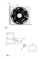
- Fig. 1 shows an example of the prior art EP1890113A1
- On the mechanical support of the optical code track 1 are many adjacent code elements arranged, which code elements embody the absolute coding 10.
- the code elements arranged in a track direction write the one-to-one position specification of the absolute coding from one code element to a next adjacent code element in a spatially resolved manner.
- the code elements are translucent rectangles which are arranged in an opaque residual area.
- the optical code track 1 is illuminated in the transmitted light principle with light from a light source. The code elements modulate the light.
- Light transmitted by the translucent rectangles is detected by a sensor along the track direction, light not transmitted by the opaque residual areas is not detected by the sensor.
- the translucent rectangles are displayed on the sensor as a shadow.
- the sensor generates status signals for detected light.
- the optical code track and the sensor move together, the sensor detects the absolute coding as a temporal discrete sequence of discontinuous light-dark transitions.
- the absolute coding has either a one-to-one position indication or a one-to-one code.
- the position information is either determined directly from the state signals, or the code of the state signal is assigned by looking up a table a position specification.
- a center of gravity of the state signal can be determined in order to relate the determined position information with subcode element accuracy to the center of gravity of the code element.
- the width of the state signal in the track direction is referred to as the signal width
- the width of the sensor in the track direction is referred to as sensor width. From the center of gravity of the state signal is closed to a center of gravity of the code element. And from the center of gravity of the code element, a distance in the track direction to a reference position is determined.
- the status signal not only provides one-to-one position indication, but also allows the position of the code element to be determined relative to a reference position.
- positions of machine elements are determined with an accuracy of 1 micron, and theodolites measure horizontal angle and vertical angle to several hundred meters away objects with an accuracy of 0.lmgon.
- systematic and non-systematic errors in determining the position of the object must be eliminated.
- High-precision absolute value encoders therefore have a plurality of sensors which are arranged in a fixed spatial relationship to one another and which detect the absolute coding of the code track in a redundant manner. By averaging the redundantly detected absolute coding, non-systematic errors in determining the position of the object can be eliminated.
- harmonic errors have many causes. So can They are caused by unevenly arranged on the code track code elements, or caused by thermal expansion of the code track, eccentricity of the mechanical support of the code track, bearing clearance of the absolute encoder, diffraction phenomena on code elements, etc.
- the fixed spatial relationship of the sensors to one another and the uniform arrangement of the code elements of the code track represent periodic structures. Superimposition of the periodic structures can form disturbing moiré patterns in optical absolute encoders.
- the Nyquist-Shannon sampling theorem if the sampling frequency of the absolute value transmitter selected is too small, information losses in the detection of the absolute coding can occur with respect to the maximum frequency of the code elements.
- WO2011 / 064317A1 describes for this purpose a method for determining error coefficients and a method for correcting the measured value of an absolute value encoder with these error coefficients.
- the absolute encoder has at least two sensors and an optical code track.
- the sensors and the optical code track are mutually movable.
- the sensors detect the absolute coding of the optical code track as a sequence of light-dark transitions at different angular positions.
- the sensors are spaced apart at an angle of at least 50 degrees.
- An evaluation unit determines angular position values from the absolute coding detected by the sensors. By comparing the difference in the angular position values of the sensors for a plurality of different angular positions, harmonic angular errors in a Fourier series development are represented as error coefficients. The angular position values are corrected with these harmonic angle errors.
- a first object of the invention is to provide an improved method for detecting the absolute coding of an optical code track.
- a second object of the invention is to provide an optical code track and an absolute value encoder for detecting the absolute coding of the optical code track, which require as few sensors as possible and / or the least possible amount of computation for the highly accurate determination of the object.
- a third object of the invention is to provide a method of manufacturing an optical code track that is cost-effective with existing and proven coating techniques.
- a further object of the invention is to provide an optical code track and an absolute encoder for detecting the absolute coding of the optical code track, which have a high availability even under harsh operating conditions.
- One aspect of the invention relates to a method for detecting absolute coding, the absolute coding is embodied by code elements of an optical code track, with a lighting of the code elements with light; modulating a portion of the illuminating light on code elements; with detecting the absolute coding as modulated light; and with continuously varying modulating the light on adjacent code elements.
- optical code track which optical code track comprises a mechanical support, preferably in the form of a disk or a belt; which mechanical carrier at least partially has code elements; with adjacent code elements that continuously modulate illuminating light.
- the absolute coding is embodied as an aperture diaphragm with a continuous variation of code levels formed in the code track extension direction (ie shutter opening variables which vary continuously along the code track extension direction).
- an aperture stop can embody absolute coding, with code elements having continuously varying code levels.
- the aperture stop consists of individual code elements which are arranged in track direction and have different widths.
- the absolute coding may also be embodied as a dot matrix with continuous variation of dot densities of adjacent code elements.
- a dot matrix can embody absolute coding, with code elements having continuously varying dot densities.
- the Dot matrix consists of a grid with a varying track density of dark spots on a light background.
- the absolute coding is embodied as a polarizer with continuous variation of polarization efficiencies of adjacent code elements.
- a polarizer can embody absolute coding.
- a polarizer is an optical means which changes a polarization state of light having a specific polarization efficiency.
- a distinction is made between polarization by scattering, polarization by reflection, polarization by absorption and polarization by birefringence.
- Yet another aspect of the invention relates to a system for detecting the absolute coding of the optical code track; which system has an absolute encoder with an optical sensor; which absolute encoder generates at least one status signal for detected modulated light; which state signal has a signal width, which signal width is smaller than a sensor width of the sensor.
- the center of gravity of the state signal can only be determined with a minimum error if the signal width of the state signal is exactly an integral multiple of the sensor element width (ie the pixel pitch) of the sensor. As soon as the signal width deviates from this, the center of gravity of the state signal can only be determined with a more or less large error.
- the error is maximum if the signal width of the State signal deviates half Sensorelelementweite from the integer multiple of the sensor element width. Now it is practically and technically not feasible to produce a signal width that is exactly a multiple of the Sensorelelementweite under all operating conditions.
- the signal width is affected by changing factors such as magnification, ambient temperature, production tolerances of optical code track and absolute value encoders, etc.
- the code element can be imaged by a lens optics on the sensor, each lens optics is associated with a distortion that maps the code element location-dependent with different width on the sensor, for which image the sensor generates a status signal.
- Yet another aspect of the invention relates to a method of making the optical code track in which a mechanical carrier of the optical code track is provided; on which mechanical support, at least in regions, a coating is applied; in which coating code elements are structured, which code elements modulate illuminating light; the code elements are structured such that illuminating light is modulated on adjacent code elements with a continuous variation.
- FIG. 2 shows an absolute encoder 2, which detects an absolute code 10 of an optical code track 1 with an optical sensor 20.
- the optical code track 1 is fixedly arranged on an object 4. Both the optical code track 1 and the object 4 can have any size, shape and shape.
- the optical code track 1 has, for example, the shape of a disc, a band, etc.
- an object position can be determined absolutely.
- the object 4 is schematically designed as a cylinder and the optical code track 1 is arranged on the outside of the strip on the circumference of the object 4 and surrounds the circumference completely.
- the absolute encoder 2 communicates with an evaluation unit 3. The position of the absolute encoder 2 and the optical code track 1 to each other is variable.
- the absolute value encoder 2 has a light source, the light source generates light 21, which light 21 illuminates the optical code track 1.
- the light 21 consists of electromagnetic waves such as radio waves, microwaves, visible light, etc.
- modulated light 21 ' is detected by the optical sensor 20.
- modulation of light is understood to mean a physical interaction of light 21 with code elements 100, 100 'of the optical code track 1. Modulation of light includes the scattering of light, the reflection of light, the refraction of light, the diffraction of light, the absorption of light, the polarization of light, etc.
- the optical sensor 20 is, for example, a register of sensor elements, such as Charge-Coupled Device (CCD), a Complementary Metal Oxide Semiconductor (CMOS), etc ..
- the sensor has thereby juxtaposed photo-receiving elements, wherein the sensor width in the X direction (and for a surface array possibly also in the Y direction) in a number of the individual photoreceptor elements (pixels).
- the X direction is the sensor track direction.
- the optical sensor 20 is according to FIGS. 12 to 22 For example, a line array with 1000 photoreceptor elements (pixels) in the X direction.
- the constantly varying modulation for the code projection generation not only illuminates individual receiving elements of the sensor either "not at all or completely", but also produces many different intermediate values (gray values) for the illumination of the individual receiving elements (pixels). wherein the illumination intensity over the course of the individual pixels along the sensor line then corresponds to the continuously varying modulation in the context of the code projection.
- the absolute value encoder 2 generates at least one status signal 200 from the detected code projection for modulated light 21 'detected by the optical sensor 20 dependent sensor output and communicates this status signal 200 to the evaluation unit 3. Details of the status signal 200 follow in the FIGS. 12 to 24 , The communication 23 of the state signal 200 can be arbitrary, in particular it can be cable-based, radio-supported, etc. With knowledge of the present invention, the person skilled in the art can execute the absolute value encoder with an evaluation unit integrated in the housing as a single unit.
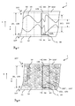
- the FIGS. 3 to 11 show several embodiments of an optical code track 1.
- the optical code track 1 has, for example, a mechanical support 11 made of glass, plastic, metal, etc.
- the FIGS. 3 to 6 show the optical code track 1 in cross section along the track direction (X direction) and in cross section in the Y direction transverse to the track direction. At least in regions, for example, a coating 12 of chromium, silicon nitride and molybdenum, etc. is applied to the mechanical support 11.
- the FIGS. 7 to 11 show the optical code track 1 in view. In the coating 12, for example, photolithographic, etched or galvanized code elements 100, 100 'are patterned at least in regions.
- the areas of the mechanical support 11 that are covered after structuring and that continue to have a coating 12 are, for example, more than 90%, in particular more than 98%, light-impermeable, ie opaque, for the light 21.
- the thickness of the coating 12 of the optical code track 1 may be partially in the X direction and in the Y direction be constant.
- the coating is 1 ⁇ m thick, preferably 0.5 ⁇ m thick, preferably 0.1 ⁇ m, both in an edge region 107 and in a middle region FIGS.
- the thickness of the coating 12 may also be different for different regions of the optical code track 1.
- the thickness of the coating 12 along the Y direction may vary continuously between 0.1 ⁇ m and 1.0 ⁇ m.
- the detection of the light modulated on the code elements 100, 100 'light 21' takes place in transmitted light or incident light.
- the optical sensor 20 detects the light 21 'modulated by uncovered regions; in the incident-light method, the optical sensor 20 detects the light 21' modulated on covered regions.
- modulated light 21 ' is detected in the transmitted-light method by way of example (where, as is known per se to the person skilled in the art, this can alternatively also be done in the incident-light method).
- modulated light 21 ' is detected by way of example in the reflected-light method (whereby, again, as is known per se to the person skilled in the art, the transmitted-light method can also be used here).
- the optical sensor 20 detects the absolute coding 10 by changing the position along the X direction.
- the absolute encoders 10 embodying code elements 100, 100 'can have a constant code element width 104 in the X direction and they have a constant in the Y direction maximum code element height 105.
- the sizes of the code element width 104 and the maximum code element height 105 are in the range of several ⁇ m to several cm.
- the code elements 100, 100 ' are arranged in the Y direction with the edge distance 107 to an edge of the optical code track 1.
- the size of the edge gap 107 is constant and is in the range of several ⁇ m to several mm.
- a sensor width 24 of the optical sensor 20 along the X direction is greater than two code element widths 104 of the code elements 100, 100 ', so that in each case the code projection generated on the sensor contains a representation of at least one entire code element 100, 100' (if necessary ., the code element width can be chosen in relation to the sensor line length (ie the sensor width) so that the code projection contains many pulses generated by many code elements 100, 100 ').
- a sensor height 25 of the optical sensor 20 (in the Y direction, in other words the extent in the direction transverse to the direction of extension of the sensor line) may be greater than the maximum code element height 105 of the code elements 100, 100 '.
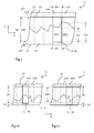
- FIGS. 7 . 9, 10 and 11 show various embodiments of an optical code track 1 with an aperture stop as absolute coding 10. While the aperture stop FIG. 7 has a double-sided continuously varying aperture aperture, show the FIGS. 9, 10 and 11 one-sided varying aperture apertures.
- the coating 12 is thus structured such that it forms an aperture diaphragm.
- each code element 100, 100 ' has a single contiguous area uncovered by coating 12.
- Code heights 101, 101 'of adjacent code elements 100, 100' vary continuously, ie steadily, in the direction of the code track extension.
- the code height 101, 101 ' is the extent measured from the edge region 107 of the coating 12 of a code element 100, 100' in the Y direction.
- the code height 101, 101 'thus indicates the boundary of the coating 12 on the mechanical support 11.
- the aperture stop has a boundary of the coating 12 in the form of curved aperture stop sections; according to FIG. 9 the aperture stop has a boundary of the coating 12 in the form of rectilinear prong sections.
- the FIG. 8 shows an embodiment of an optical code track 1 with a dot matrix as absolute coding 10.
- the dot density 102, 102 'of adjacent code elements 100, 100' varies continuously.
- the mechanical support 11 is both in the edge region 107 of the code elements 100, 100 'and in the central region of the code elements 100, 100'. only partially covered with coating 12 in the form of dots.
- the area uncovered by coating 12 may be continuous, but it may also be discontinuous.
- Point densities 102, 102 'of adjacent code elements 100, 100' vary continuously. Due to the continuous variation of the point densities 102, 102 ', illuminating light 21 is modulated with continuous variation.
- the dot density 102, 102 ' is the density of dots measured per unit area in the XY coordinate system.
- the size of the dots may be constant for the entire optical code track 1, such as 10 ⁇ m, 5 ⁇ m, etc .; However, the size of the dots may also be different for different areas of the optical code track 1, such as in a first area 5 ⁇ m, in a second area 6 ⁇ m, etc ..
- an optical code track 1 according to the FIGS. 3 to 11 can be realized with a polarizer as absolute coding 10, which polarizer a polarization state of the light 21 with a specific polarization efficiency 103, 103 'changed so that the polarization efficiency 103, 103' of adjacent code elements 100, 100 'continuously varies.
- a polarizer as absolute coding 10
- polarizer a polarization state of the light 21 with a specific polarization efficiency 103, 103 'changed so that the polarization efficiency 103, 103' of adjacent code elements 100, 100 'continuously varies.
- illuminating light 21 with continuous variation is modulated.
- a distinction is made between polarization by scattering, polarization by reflection, polarization by absorption and polarization by birefringence. Polarization by scattering, absorption and birefringence can be achieved with the embodiments according to the FIGS. 7 . 9, 10 and 11 realize.
- Polarization by reflection can be with the embodiment according to FIG. 8 realize.
- the polarization efficiency 103, 103 ' has a specific function of code height 101, 101'; according to FIG. 8 the polarization efficiency 103, 103 'is a specific function of the point density 102, 102'.
- the polarization efficiency 103, 103 ' may also be varied across the thickness of the coating 12, the nature of the materials of the coating 12 and the mechanical support 11, etc.
- FIGS. 10 and 11 show an exemplary detection of the absolute coding 10 on two adjacent code elements 100, 100 '.
- the optical sensor 20 detects according to FIG. 10 modulated light 21 'from a first code element 100 and according to FIG. 11 the optical sensor 20 detects modulated light 21 'from a second code element 100'.
- the optical code track 1 has, for example, a mechanical support 11 in the form of a disk, which disk in the Y direction has an eccentricity 16, 16 'caused by the production process.
- the eccentricity 16 in the first code element 100 is greater than the eccentricity 16 'in the second code element 100'.
- the optical sensor 20 has a sensor height 25 along the Y direction which is larger than the code element height 105 of the code elements 100, 100 'so as to compensate for and avoid eccentricities 16, 16' of the optical code track 1 with respect to the Y direction in that code elements 100, 100 'are detected incompletely.
- a position (eg in the form of a defined main point or a center of gravity 301 of the state signal 200) can be determined for each state signal 200.
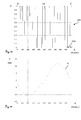
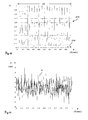
- FIGS. 12 to 23 show how an error F in determining the positions of the state signals 200 depends on the signal width 204 of the state signals 200 and the pixel pitch of the individual sensing elements of the sensor 20.
- the Figures 12 . 14 . 16 . 18 . 20 and 22 show the state signals 200 and the Figures 13 . 15 . 17 . 19 . 21 and 23 show the errors F.
- the 16 . 18 . 20 and 22 is a normalized signal strength S, which outputs the individual detection elements (pixels) of the code projection sensor; the abscissa of the Figures 12 . 14 . 16 . 18 . 20 and 22 is the X direction (extension direction) of the sensor.
- the sensor 20 consists for example of a line array with 1000 in the X direction juxtaposed sensor elements. All 1000 sensor elements form the sensor width 24.
- the ordinates of the Figures 13 . 15 . 17 . 19 . 21 and 23 is the error F; the abscissa of the Figures 13 . 15 . 17 . 19 . 21 and 23 is the X direction.
- the error F in determining the centroids 301 of the state signals 200 is more or less dependent on a centroid shift V.
- the centroid shift V is caused or simulated by quasi-stochastic errors.
- FIG. 12 shows a single rectangular state signal 200.
- a rectangular state signal 200 is generated for detected light that is applied to rectangular code elements such as these are known from the prior art, has been modulated.
- state signal 200 has a signal width 204 of fifteen plus one half pixel.
- the signal width 204 is a non-integer multiple of the pixel pitch.
- FIG. 13 shows the error F for such a selection of signal width 204 in relation to the pixel pitch for the detection of a rectangular state signal.
- the center of gravity shift V is in the range of zero to a whole pixel.
- the error F Due to the fact that the state signal is rectangular and the signal width does not form an integer multiple of the pixel pitch, the error F has a sawtooth profile in the range from -60 nm to + 60 nm; the standard deviation of the error F is 36nm.
- FIG. 14 shows a single bell-shaped state signal 200.
- a bell-shaped state signal 200 is generated for detected light 21 'which has been modulated on inventive code elements 100, 100' (ie continuously varying), which inventive continuous variation to low diffraction phenomena and few quasi-stochastic errors in State signal 200 leads.
- the state signal 200 has a signal width 204 of, for example, fifteen plus one half pixel.
- the signal width 204 is a non-integer multiple of the pixel pitch.
- FIG. 15 shows the error F in nm for such a selection of signal width 204 in relation to the pixel pitch.
- the center of gravity shift V is in the range of zero to a whole pixel.
- the error F is due to the bell-shaped state signal only a noise in the range of 0.7 * 10 -8 nm to 1.5 * 10 -8 nm; the standard deviation of the error F is 1.1 * 10 -8 nm.
- FIG. 16 shows a single rectangular state signal 200 with a signal width 204 of fifteen pixels.
- the signal width 204 is an integer multiple of the sensor elements.
- FIG. 17 shows the error F for such a ratio of signal width 204 to pixel pitch.
- the center of gravity shift V is in the range of zero to a whole pixel.
- the error F is noise and varies in the range of -7.54 * 10 -8 nm to -7.44 * 10 -8 nm; the standard deviation of the error F is -7.49 * 10 -8 nm.
- FIG. 18 Figure 12 shows a multiple rectangular state signal 200 with different signal width 204 in the range of fourteen plus one half pixel to fifteen plus one half pixel.
- the error F for such a ratio of signal width 204 to the pixel pitch is in FIG. 19 to see.
- the center of gravity shift V is in the range of zero to a whole pixel.
- the center of gravity shift V shows a rounded sawtooth-like course and varies in the range of -11nm to + llnm; the standard deviation of the error F is 7.9nm.
- FIG. 20 shows a generated by the invention continuously varying modulation multiple bell-shaped state signal 200 with different signal width 204 in the range, for example, from fourteen plus a half pixel to fifteen plus one half pixel.
- the error F for such a configuration of the code i.e., the signal width 204 is different in width over the course of the code in the code track direction, and is illustratively varied between fourteen plus one half and fifteen plus one half pixel
- the center of gravity shift V is in the range of zero to a whole pixel.
- the center of gravity shift V is a Noise and varies in the range of -7nm to + 9nm; the standard deviation of the error F is 2.4nm.
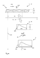
- FIG. 22 shows the detection of modulated on a code element 100 'of the optical code track 1 light 21' by the absolute value encoder 2.
- a status signal 200 is generated by the absolute value encoder 2.
- the code element 100 ' is thus imaged as a state signal 200 (ie, as a code projection) on a sensor 20 of the absolute encoder 2 and detected by the sensor 20.
- the status signal 200 is communicated to the evaluation unit 3.
- the evaluation unit 3 has a microprocessor and a computer-readable data memory.
- a computer program product is loaded from the computer-readable data memory (which can be located either locally in the evaluation unit 3 or externally and connected via the Internet) to the microprocessor of the evaluation unit 3.
- the evaluation unit 3 can be a stationary computer such as a personal computer (PC), a board with a microcomputer with a programmable logic or, or a mobile computer such as a laptop, smartphone, etc.
- the program code according to the invention can therefore be present in the context of a computer program product stored on a machine-readable carrier or a computer data signal embodied by an electromagnetic wave, the program code being suitable from an absolute coding 10 detected by the system according to the invention described above the optical code track 1 to determine the object position when the program is loaded into the microprocessor of the evaluation unit 3 and executed.
- the evaluation unit 3 determines a position output 300 for the communicated status signal 200.
- the status signal 200 has either a one-to-one position indication or a one-to-one code.
- the position information is either determined directly from the state signal 200, or the code of the state signal 200 is assigned by looking up in a digital table, a position indication.
- the digital table is likewise stored in the computer-readable data memory and can be loaded into the microprocessor of the evaluation unit 3.
- the evaluation unit 3 also determines a position (eg in the form of a center of gravity 301) of the communicated state signal 200 and determines a distance 302 from the center of gravity 301 to a reference position 240 of the absolute encoder 2. The object position thus becomes absolute from the sum of the position output 300 and the distance 302 certainly.
Landscapes
- Physics & Mathematics (AREA)
- General Physics & Mathematics (AREA)
- Optical Transform (AREA)
- Transmission And Conversion Of Sensor Element Output (AREA)
Priority Applications (5)
| Application Number | Priority Date | Filing Date | Title |
|---|---|---|---|
| EP12175130.9A EP2682718A1 (fr) | 2012-07-05 | 2012-07-05 | Procédé de saisie d'un codage absolu d'une piste de code optique |
| EP13735009.6A EP2870431B1 (fr) | 2012-07-05 | 2013-07-05 | Procédé de détection d'un codage absolu d'une piste de code optique |
| US14/412,670 US9823097B2 (en) | 2012-07-05 | 2013-07-05 | Method for determining absolute coding of an optical coding track |
| PCT/EP2013/064268 WO2014006187A2 (fr) | 2012-07-05 | 2013-07-05 | Procédé de détection d'un codage absolu d'une piste de code optique |
| CN201380035884.8A CN104412070B (zh) | 2012-07-05 | 2013-07-05 | 记录编码的方法和系统、实施编码的轨道及轨道制作方法 |
Applications Claiming Priority (1)
| Application Number | Priority Date | Filing Date | Title |
|---|---|---|---|
| EP12175130.9A EP2682718A1 (fr) | 2012-07-05 | 2012-07-05 | Procédé de saisie d'un codage absolu d'une piste de code optique |
Publications (1)
| Publication Number | Publication Date |
|---|---|
| EP2682718A1 true EP2682718A1 (fr) | 2014-01-08 |
Family
ID=48771428
Family Applications (2)
| Application Number | Title | Priority Date | Filing Date |
|---|---|---|---|
| EP12175130.9A Withdrawn EP2682718A1 (fr) | 2012-07-05 | 2012-07-05 | Procédé de saisie d'un codage absolu d'une piste de code optique |
| EP13735009.6A Active EP2870431B1 (fr) | 2012-07-05 | 2013-07-05 | Procédé de détection d'un codage absolu d'une piste de code optique |
Family Applications After (1)
| Application Number | Title | Priority Date | Filing Date |
|---|---|---|---|
| EP13735009.6A Active EP2870431B1 (fr) | 2012-07-05 | 2013-07-05 | Procédé de détection d'un codage absolu d'une piste de code optique |
Country Status (4)
| Country | Link |
|---|---|
| US (1) | US9823097B2 (fr) |
| EP (2) | EP2682718A1 (fr) |
| CN (1) | CN104412070B (fr) |
| WO (1) | WO2014006187A2 (fr) |
Cited By (1)
| Publication number | Priority date | Publication date | Assignee | Title |
|---|---|---|---|---|
| US9846063B2 (en) | 2014-02-18 | 2017-12-19 | Hexagon Technology Center Gmbh | Linear encoder having calibration functionality |
Citations (7)
| Publication number | Priority date | Publication date | Assignee | Title |
|---|---|---|---|---|
| SU1246372A1 (ru) * | 1984-11-27 | 1986-07-23 | Институт радиофизики и электроники АН АрмССР | Преобразователь угла поворота вала в код |
| US4931636A (en) * | 1988-08-26 | 1990-06-05 | The Boeing Company | Two wavelength optical sensor and sensing system |
| US4964727A (en) * | 1988-11-23 | 1990-10-23 | The Boeing Company | Multi-track analog optical sensing system and method |
| WO1992004776A1 (fr) * | 1990-08-31 | 1992-03-19 | The Boeing Company | Systeme de detection multipiste multiniveau |
| WO2001061280A1 (fr) * | 2000-02-15 | 2001-08-23 | Leopold Kostal Gmbh & Co. Kg | Disque code pour une unite optoelectronique servant a mesurer un deplacement ou un angle |
| EP1890113A1 (fr) | 2006-08-18 | 2008-02-20 | Leica Geosystems AG | Capteur angulaire optoélectronique et procédé destiné à la détermination d'un angle de rotation autour d'un axe |
| WO2011064317A2 (fr) | 2009-11-26 | 2011-06-03 | Leica Geosystems Ag | Procédé d'étalonnage et procédé de mesure angulaire pour un dispositif de mesure angulaire, ainsi que dispositif de mesure angulaire |
Family Cites Families (4)
| Publication number | Priority date | Publication date | Assignee | Title |
|---|---|---|---|---|
| DD201500B1 (de) * | 1981-10-23 | 1987-01-21 | Woschni Hans Guenter | Verfahren zur bestimmung der lage einer optisch wirksamen struktur |
| DE59805985D1 (de) * | 1997-06-28 | 2002-11-21 | Kostal Leopold Gmbh & Co Kg | Verfahren zum bestimmen der absoluten winkelstellung des lenkrades eines kraftfahrzeuges sowie optoelektronischer lenkwinkelsensor |
| US7078677B2 (en) * | 2004-01-21 | 2006-07-18 | Chee Keong Chong | Optical encoder disk having a region that continuously increases in size |
| US8309906B2 (en) * | 2010-06-10 | 2012-11-13 | Mitutoyo Corporation | Absolute optical encoder with long range intensity modulation on scale |
-
2012
- 2012-07-05 EP EP12175130.9A patent/EP2682718A1/fr not_active Withdrawn
-
2013
- 2013-07-05 US US14/412,670 patent/US9823097B2/en active Active
- 2013-07-05 CN CN201380035884.8A patent/CN104412070B/zh active Active
- 2013-07-05 WO PCT/EP2013/064268 patent/WO2014006187A2/fr not_active Ceased
- 2013-07-05 EP EP13735009.6A patent/EP2870431B1/fr active Active
Patent Citations (7)
| Publication number | Priority date | Publication date | Assignee | Title |
|---|---|---|---|---|
| SU1246372A1 (ru) * | 1984-11-27 | 1986-07-23 | Институт радиофизики и электроники АН АрмССР | Преобразователь угла поворота вала в код |
| US4931636A (en) * | 1988-08-26 | 1990-06-05 | The Boeing Company | Two wavelength optical sensor and sensing system |
| US4964727A (en) * | 1988-11-23 | 1990-10-23 | The Boeing Company | Multi-track analog optical sensing system and method |
| WO1992004776A1 (fr) * | 1990-08-31 | 1992-03-19 | The Boeing Company | Systeme de detection multipiste multiniveau |
| WO2001061280A1 (fr) * | 2000-02-15 | 2001-08-23 | Leopold Kostal Gmbh & Co. Kg | Disque code pour une unite optoelectronique servant a mesurer un deplacement ou un angle |
| EP1890113A1 (fr) | 2006-08-18 | 2008-02-20 | Leica Geosystems AG | Capteur angulaire optoélectronique et procédé destiné à la détermination d'un angle de rotation autour d'un axe |
| WO2011064317A2 (fr) | 2009-11-26 | 2011-06-03 | Leica Geosystems Ag | Procédé d'étalonnage et procédé de mesure angulaire pour un dispositif de mesure angulaire, ainsi que dispositif de mesure angulaire |
Cited By (1)
| Publication number | Priority date | Publication date | Assignee | Title |
|---|---|---|---|---|
| US9846063B2 (en) | 2014-02-18 | 2017-12-19 | Hexagon Technology Center Gmbh | Linear encoder having calibration functionality |
Also Published As
| Publication number | Publication date |
|---|---|
| US20150144775A1 (en) | 2015-05-28 |
| WO2014006187A3 (fr) | 2014-04-10 |
| EP2870431A2 (fr) | 2015-05-13 |
| WO2014006187A2 (fr) | 2014-01-09 |
| US9823097B2 (en) | 2017-11-21 |
| EP2870431B1 (fr) | 2016-09-07 |
| CN104412070A (zh) | 2015-03-11 |
| CN104412070B (zh) | 2017-06-06 |
Similar Documents
| Publication | Publication Date | Title |
|---|---|---|
| DE4226683B4 (de) | Optischer Bewegungsaufnehmer | |
| EP2108105B1 (fr) | Procédé de détermination d'une grandeur d'influence sur l'excentricité dans un dispositif de mesure d'angle | |
| DE102015006745B4 (de) | Skala und optischer Codierer | |
| DE112011104918T5 (de) | Optischer Geber | |
| CH690971A5 (de) | Verfahren zur Messung und Verwertung einer Verschiebung eines Abtastkopfes gegenüber einer Massverkörperung und optischer Messgeber zur Durchführung dieses Verfahrens. | |
| EP3511680B1 (fr) | Dispositif de mesure de position | |
| DE102015205738A1 (de) | Bewegungsmesssystem einer Maschine und Verfahren zum Betreiben des Bewegungsmesssystems | |
| DE69618441T2 (de) | Optoelektronischer drehkodierer | |
| EP0804716B1 (fr) | Systeme photoelectrique de mesure de distance et d'angle destine a mesurer le deplacement de deux objets l'un par rapport a l'autre | |
| DE112014002505T5 (de) | Verfahren zum Selbstkalibrieren eines Drehgebers | |
| EP2388556B1 (fr) | Indicateur de position optique | |
| DE10132521A1 (de) | Positionsmesseinrichtung | |
| DE102019210274A1 (de) | Optische Positionsmesseinrichtung | |
| EP0645607B1 (fr) | Dispositif de production de signaux périodiques sans harmonie | |
| DE102007024593A1 (de) | Maßstab für eine Positionsmesseinrichtung und Positionsmesseinrichtung | |
| DE102021102053B4 (de) | Bestimmung einer Position | |
| EP2870431B1 (fr) | Procédé de détection d'un codage absolu d'une piste de code optique | |
| EP1617182B1 (fr) | Dispositif d'établissement de la position | |
| EP2963391B1 (fr) | Dispositif de mesure de position | |
| EP2878930B1 (fr) | Dispositif de mesure de position | |
| EP2570780A2 (fr) | Dispositif de mesure de position rotatif | |
| EP1477771A2 (fr) | Alignement de phase pour des capteurs d'angle et déplacement | |
| DE102009005536B4 (de) | Drehwinkelsensor | |
| DE4423877A1 (de) | Längen- oder Winkelmeßeinrichtung | |
| DE4202560A1 (de) | Vorrichtung zur erzeugung oberwellenfreier periodischer signale |
Legal Events
| Date | Code | Title | Description |
|---|---|---|---|
| PUAI | Public reference made under article 153(3) epc to a published international application that has entered the european phase |
Free format text: ORIGINAL CODE: 0009012 |
|
| AK | Designated contracting states |
Kind code of ref document: A1 Designated state(s): AL AT BE BG CH CY CZ DE DK EE ES FI FR GB GR HR HU IE IS IT LI LT LU LV MC MK MT NL NO PL PT RO RS SE SI SK SM TR |
|
| AX | Request for extension of the european patent |
Extension state: BA ME |
|
| STAA | Information on the status of an ep patent application or granted ep patent |
Free format text: STATUS: THE APPLICATION IS DEEMED TO BE WITHDRAWN |
|
| 18D | Application deemed to be withdrawn |
Effective date: 20140709 |