EP2682747B1 - Dispositif de sélection de spermatozoides - Google Patents
Dispositif de sélection de spermatozoides Download PDFInfo
- Publication number
- EP2682747B1 EP2682747B1 EP12174599.6A EP12174599A EP2682747B1 EP 2682747 B1 EP2682747 B1 EP 2682747B1 EP 12174599 A EP12174599 A EP 12174599A EP 2682747 B1 EP2682747 B1 EP 2682747B1
- Authority
- EP
- European Patent Office
- Prior art keywords
- chamber
- vessel
- displacement means
- fluid
- displacement
- Prior art date
- Legal status (The legal status is an assumption and is not a legal conclusion. Google has not performed a legal analysis and makes no representation as to the accuracy of the status listed.)
- Not-in-force
Links
- 238000006073 displacement reaction Methods 0.000 claims description 118
- 210000000582 semen Anatomy 0.000 claims description 79
- 239000012530 fluid Substances 0.000 claims description 69
- 239000007788 liquid Substances 0.000 claims description 29
- 238000000034 method Methods 0.000 claims description 18
- 238000007789 sealing Methods 0.000 claims description 9
- 210000000947 motile cell Anatomy 0.000 claims description 8
- 210000004027 cell Anatomy 0.000 claims description 4
- 238000004891 communication Methods 0.000 claims description 3
- 239000000463 material Substances 0.000 description 10
- 238000010187 selection method Methods 0.000 description 9
- 238000011109 contamination Methods 0.000 description 8
- 108020004414 DNA Proteins 0.000 description 7
- 239000011521 glass Substances 0.000 description 7
- 102000053602 DNA Human genes 0.000 description 5
- 230000009471 action Effects 0.000 description 5
- 238000010790 dilution Methods 0.000 description 5
- 239000012895 dilution Substances 0.000 description 5
- 239000004033 plastic Substances 0.000 description 5
- 229920003023 plastic Polymers 0.000 description 5
- 239000000126 substance Substances 0.000 description 5
- 230000004899 motility Effects 0.000 description 4
- 125000006850 spacer group Chemical group 0.000 description 4
- 238000009736 wetting Methods 0.000 description 4
- 231100001074 DNA strand break Toxicity 0.000 description 3
- 230000015572 biosynthetic process Effects 0.000 description 3
- 230000004720 fertilization Effects 0.000 description 3
- 238000003780 insertion Methods 0.000 description 3
- 230000037431 insertion Effects 0.000 description 3
- 231100000182 Sperm DNA damage Toxicity 0.000 description 2
- 230000004075 alteration Effects 0.000 description 2
- 231100001075 aneuploidy Toxicity 0.000 description 2
- 208000036878 aneuploidy Diseases 0.000 description 2
- QVGXLLKOCUKJST-UHFFFAOYSA-N atomic oxygen Chemical compound [O] QVGXLLKOCUKJST-UHFFFAOYSA-N 0.000 description 2
- 230000006378 damage Effects 0.000 description 2
- 230000003247 decreasing effect Effects 0.000 description 2
- 230000000694 effects Effects 0.000 description 2
- -1 for example Substances 0.000 description 2
- 238000013467 fragmentation Methods 0.000 description 2
- 238000006062 fragmentation reaction Methods 0.000 description 2
- 239000000499 gel Substances 0.000 description 2
- 230000005484 gravity Effects 0.000 description 2
- 238000000338 in vitro Methods 0.000 description 2
- 238000007373 indentation Methods 0.000 description 2
- 229910052760 oxygen Inorganic materials 0.000 description 2
- 239000001301 oxygen Substances 0.000 description 2
- 230000008569 process Effects 0.000 description 2
- 239000012780 transparent material Substances 0.000 description 2
- 208000002312 Teratozoospermia Diseases 0.000 description 1
- 239000012141 concentrate Substances 0.000 description 1
- 238000005138 cryopreservation Methods 0.000 description 1
- 238000011161 development Methods 0.000 description 1
- 238000005516 engineering process Methods 0.000 description 1
- 230000001771 impaired effect Effects 0.000 description 1
- 238000001802 infusion Methods 0.000 description 1
- 230000009027 insemination Effects 0.000 description 1
- 230000001788 irregular Effects 0.000 description 1
- 210000003899 penis Anatomy 0.000 description 1
- 239000000843 powder Substances 0.000 description 1
- 230000035935 pregnancy Effects 0.000 description 1
- 230000001105 regulatory effect Effects 0.000 description 1
- 230000001850 reproductive effect Effects 0.000 description 1
- 230000000717 retained effect Effects 0.000 description 1
- 230000007480 spreading Effects 0.000 description 1
- 210000004291 uterus Anatomy 0.000 description 1
Images






Classifications
-
- G—PHYSICS
- G01—MEASURING; TESTING
- G01N—INVESTIGATING OR ANALYSING MATERIALS BY DETERMINING THEIR CHEMICAL OR PHYSICAL PROPERTIES
- G01N33/00—Investigating or analysing materials by specific methods not covered by groups G01N1/00 - G01N31/00
- G01N33/48—Biological material, e.g. blood, urine; Haemocytometers
- G01N33/483—Physical analysis of biological material
- G01N33/4833—Physical analysis of biological material of solid biological material, e.g. tissue samples, cell cultures
-
- B—PERFORMING OPERATIONS; TRANSPORTING
- B01—PHYSICAL OR CHEMICAL PROCESSES OR APPARATUS IN GENERAL
- B01L—CHEMICAL OR PHYSICAL LABORATORY APPARATUS FOR GENERAL USE
- B01L3/00—Containers or dishes for laboratory use, e.g. laboratory glassware; Droppers
- B01L3/50—Containers for the purpose of retaining a material to be analysed, e.g. test tubes
- B01L3/502—Containers for the purpose of retaining a material to be analysed, e.g. test tubes with fluid transport, e.g. in multi-compartment structures
-
- B—PERFORMING OPERATIONS; TRANSPORTING
- B01—PHYSICAL OR CHEMICAL PROCESSES OR APPARATUS IN GENERAL
- B01L—CHEMICAL OR PHYSICAL LABORATORY APPARATUS FOR GENERAL USE
- B01L3/00—Containers or dishes for laboratory use, e.g. laboratory glassware; Droppers
- B01L3/56—Labware specially adapted for transferring fluids
-
- C—CHEMISTRY; METALLURGY
- C12—BIOCHEMISTRY; BEER; SPIRITS; WINE; VINEGAR; MICROBIOLOGY; ENZYMOLOGY; MUTATION OR GENETIC ENGINEERING
- C12M—APPARATUS FOR ENZYMOLOGY OR MICROBIOLOGY; APPARATUS FOR CULTURING MICROORGANISMS FOR PRODUCING BIOMASS, FOR GROWING CELLS OR FOR OBTAINING FERMENTATION OR METABOLIC PRODUCTS, i.e. BIOREACTORS OR FERMENTERS
- C12M21/00—Bioreactors or fermenters specially adapted for specific uses
- C12M21/06—Bioreactors or fermenters specially adapted for specific uses for in vitro fertilization
-
- C—CHEMISTRY; METALLURGY
- C12—BIOCHEMISTRY; BEER; SPIRITS; WINE; VINEGAR; MICROBIOLOGY; ENZYMOLOGY; MUTATION OR GENETIC ENGINEERING
- C12M—APPARATUS FOR ENZYMOLOGY OR MICROBIOLOGY; APPARATUS FOR CULTURING MICROORGANISMS FOR PRODUCING BIOMASS, FOR GROWING CELLS OR FOR OBTAINING FERMENTATION OR METABOLIC PRODUCTS, i.e. BIOREACTORS OR FERMENTERS
- C12M41/00—Means for regulation, monitoring, measurement or control, e.g. flow regulation
- C12M41/46—Means for regulation, monitoring, measurement or control, e.g. flow regulation of cellular or enzymatic activity or functionality, e.g. cell viability
-
- C—CHEMISTRY; METALLURGY
- C12—BIOCHEMISTRY; BEER; SPIRITS; WINE; VINEGAR; MICROBIOLOGY; ENZYMOLOGY; MUTATION OR GENETIC ENGINEERING
- C12N—MICROORGANISMS OR ENZYMES; COMPOSITIONS THEREOF; PROPAGATING, PRESERVING, OR MAINTAINING MICROORGANISMS; MUTATION OR GENETIC ENGINEERING; CULTURE MEDIA
- C12N5/00—Undifferentiated human, animal or plant cells, e.g. cell lines; Tissues; Cultivation or maintenance thereof; Culture media therefor
- C12N5/06—Animal cells or tissues; Human cells or tissues
- C12N5/0602—Vertebrate cells
- C12N5/0608—Germ cells
- C12N5/0612—Germ cells sorting of gametes, e.g. according to sex or motility
-
- B—PERFORMING OPERATIONS; TRANSPORTING
- B01—PHYSICAL OR CHEMICAL PROCESSES OR APPARATUS IN GENERAL
- B01L—CHEMICAL OR PHYSICAL LABORATORY APPARATUS FOR GENERAL USE
- B01L2300/00—Additional constructional details
- B01L2300/08—Geometry, shape and general structure
- B01L2300/0861—Configuration of multiple channels and/or chambers in a single devices
- B01L2300/087—Multiple sequential chambers
Definitions
- the present invention relates to a device for spermatozoa selection. More specifically, the present invention relates to a device for spermatozoa selection having a first chamber that is adapted to receive a first, seminal fluid and a second chamber that is adapted to receive a second fluid, the first chamber and the second chamber being fluidly connected by at least one duct.
- the devices and methods of the present invention can be used to increase the quality of semen samples, and in particular to select and concentrate spermatozoa for motility and/or maturity.
- sperm sample quality includes meiotic alterations, aneuploidy or sperm DNA damage, particularly sperm DNA fragmentation.
- the selection device disclosed in WO-A2 03/031564 is illustrated in Figures 1 and 2 .
- the selection device comprises a first bridge element 3 having four channels 6a-6d and a chamber element 27 having a first ring-shaped chamber 1 for receiving seminal fluid 13 and a second chamber 2 for receiving a medium 12a, the second chamber 12a being connected to the first ring-shaped chamber 1 over a ring-shaped connection 5.
- the bridge element 3 comprises four boundary walls 4a-4e forming the channels 6a-6d, an additional channel 7 being formed by the boundary wall 4e with the boundary wall of the ring-shaped connection 5 when the bridge element is fitted on the chamber element 27.
- selection is performed by filling seminal fluid 13 with spermatozoa into the first ring-shaped chamber 1 such that said seminal fluid does not reach openings 8a-8d and 9 of the channels on the side of the ring-shaped chamber 1 and fitting the bridge element 3 onto the chambers 1, 2. Subsequently, the medium 12a is filled into the chamber 2 over the central opening 29 such that the channels 6a-6d and 7 are filled with medium 12a. Also the seminal fluid 13 in the first ring-shaped chamber 1 may be covered with medium until reaching openings 8a-8d and 9 of the channels on the side of the ring-shaped chamber 1.
- US-A-20120052485 also describes a selection device with two chambers.
- the quality of spermatozoa collected in the central chamber 2 of the selection device described above, including spermatozoa yield, is highly dependant upon the volume of seminal fluid filled into the first ring-shaped chamber 1.
- the prior selection device is optimized for specific amounts of seminal fluid and smaller volumes have to be compensated by using additional medium.
- additional medium it is believed that the increasing volume of medium required in the first ring-shaped chamber will lead to a lower density of spermatozoa in the central chamber.
- the efficiency of prior art selection devices may be reduced in particular when using seminal fluid volumes of 1 ml or less.
- many male patients requiring spermatozoa selection e.g. for in-vitro fertilization procedures, provide semen samples of 2 ml or less.
- prior art devices might not function ideally if too much or too little medium is used.
- spermatozoa may be mechanically and/or chemically damaged (e.g., due to contact with atmospheric O 2 ) during this procedure, in particular, when attempting to spread small volumes of seminal fluid evenly across the surface of said first ring-shaped chamber 1. It is further believed that higher dilution of the sperm sample may increase the time required for the selection procedure. This might affect spermatozoa quality (e.g., due to chemical damage) and could allow spermatozoa of lower quality to reach the central chamber 2.
- the quality of seminal fluids may be improved substantially by placing a seminal fluid in the first chamber of the above selection device, filing a second chamber of a selection device with a medium for receiving DNA strand break-free spermatozoa and connecting both chambers by a bridge element such that a fluid bridge is formed between the first chamber and the second chamber, which allows the DNA strand break-free spermatozoa to move from said first chamber to said second chamber.
- spermatozoa with strand breaks may be drawn from the first chamber through the fluid bridge when collecting the DNA strand break-free spermatozoa from the second chamber. Without being bound by theory, it is assumed that a slight macroscopic current from the first chamber through the liquid bridge into the second chamber may be caused when the sample is collected.
- a further object of the present invention is to provide an improved selection device and method that does not require dilution of the seminal fluid for selection procedures or reduces the amount of dilution required.
- a further object of the present invention is to provide an improved selection device and method where the same amount of medium may be used irrespectively of the volume of seminal fluid available.
- a further object of the present invention is to provide an improved selection device and method wherein the exposure of the seminal fluid to oxygen before, during and/or after the selection procedure is reduced.
- a further object of the present invention is to provide a selection device and method wherein wetting of the fluid connection is improved.
- a further object of the present invention is to reduce the time required for the selection procedure.
- the terms “upper” and “lower” denominate those parts of the device located closer to the upper end and the lower end of the device, respectively, when the assembled device is held in an upright manner such that the first and second fluids can be received in the chambers.
- the device for spermatozoa selection comprises a first chamber configured to receive a first, seminal fluid; a second chamber configured to receive a second fluid, the second chamber being in fluid communication with the first chamber by means of at least one duct having a first opening to the first chamber and a second opening to the second chamber; and a displacement means adapted to displace at least some of the first, seminal fluid towards or to the first opening.
- the displacement means is adapted to displace the first, seminal fluid such that the upper surface, i.e., the filling level, of the first, seminal fluid is arranged at a predetermined distance from the first opening.
- the device of the present disclosure can be used with different volumes of first, seminal fluid.
- the displacement means allows adapting the volume and/or the shape of the first chamber such that it may be used with seminal fluid volumes as small as 1 ml or less, preferably 0.5 ml or less. Semen samples of small volume, therefore, require less or no dilution.
- the term fluid may relate to any fluid that allows self-propelled movement of motile cells, in particular liquids or gels.
- each of the first and second fluids may also be denominated as liquid or gel.
- the first, seminal fluid preferably is a seminal fluid which might be of poor quality, such as a seminal fluid comprising a substantial amount of spermatozoa with decreased motility and/or maturity, particularly spermatozoa with meiotic alterations, aneuploidy or sperm DNA damage, particularly sperm DNA fragmentation, e.g. DNA strand breaks.
- the first fluid may comprise at least 15 % oligo-, at least 32 % astheno-, and/or at least 4 % teratozoospermia based on the total amount of spermatozoa in the fluid.
- the first, seminal fluid may be a semen sample (i.e. ejaculate) of a patient.
- the first fluid may also be a fluid with other motile cells, which may also be selected by the device of the present invention.
- the first, seminal fluid comprises a substantial amount of spermatozoa with DNA strand breaks.
- the second fluid preferably is a medium for receiving spermatozoa or other motile cells, e.g., a buffer medium. Selected cells are preferably received in the second fluid contained in the second chamber during the selection process.
- the second fluid may then be extracted, e.g. by means of a pipette, and used in or further processed for artificial reproductive technologies (e.g., artificial insemination), cryopreservation or diagnostic purposes. Alternatively, one or several ova may be located in the second chamber. Such configuration may be used, for example, to simulate more closely a natural and physiological selection of sperm during in-vitro fertilization.
- the duct When the duct is filled with a liquid, the duct preferably provides a liquid bridge between the first chamber and the second chamber.
- spermatozoa in the first chamber can move along this liquid bridge to the second chamber when the fluids in the first and second chambers reach the first and second openings of the duct, respectively.
- the first chamber may be provided by a vessel with a closed lower end, preferably a tubular vessel, such that the first, seminal fluid gathers at said closed lower end under the effect of gravity.
- the closed lower end may be of any suitable shape, for example conical, truncated, rounded (e.g., hemispherical) or flat.
- the lower end of the vessel may be shaped to be self-standing.
- the lower end may be provided with a stand, which may be formed by a cylindrical protrusion projecting over the closed lower end.
- the vessel may further be provided with an open upper end, through which the first, seminal fluid may be brought into the first chamber, e.g., by introducing it with a pipette.
- the vessel may be formed of any suitable material, for example, plastics or glass. Translucent or transparent materials are preferred.
- the displacement means comprises a displacement element (which may also be denominated as a displacement body) and may comprise a shaft for manipulating the displacement means.
- the displacement element preferably is located at the lower end of the displacement means.
- the shaft preferably is hollow and opens out into the second chamber.
- the shaft and the second chamber may be fluidly connected such that the second fluid can be filled into the second chamber through the shaft and/or such that the second fluid can be collected by extending a pipette through said shaft into the second chamber, for example, once the separated spermatozoa are contained therein.
- the displacement element and the shaft may be integrally formed or connected in a fixed or detachable manner. Any suitable material, for example, plastics or glass, may be used to form the displacement body and/or the shaft. Again, translucent or transparent materials are preferred.
- the displacement means preferably is received within the first chamber and/or the vessel in a slidable manner, thereby ensuring safe and easy manipulation of the device. More preferably, the displacement means is concentrically received in the vessel and slidable along the vessel's longitudinal axis. Spacers and/or guides may be used to properly define the position of the displacement means and guide the displacement means within the vessel. Alternatively or additionally, the vessel and the displacement means (and/or further components connected therewith) may be provided with interacting threaded portions in order to guide the displacement means into the vessel and/or in order to maintain the displacement means at a certain position relative to the vessel during the selection procedure.
- the second chamber may be located in the vessel when the device is assembled. As such, the second chamber forms in use a "central" or “inner” chamber, while the first chamber forms in use a “surrounding" or “outer” chamber. In other embodiments, an outer receptacle may form the second chamber and receive a vessel forming the first chamber therein.
- the second chamber may have a volume of 0.5 ml or less. In embodiments, part of this volume may be provided by the hollow shaft.
- At least a part of the displacement element may have a hemispherical, substantially hemispherical, conical, substantially conical, cylindrical, or substantially cylindrical outer surface.
- the outer surface of the displacement means may or may not match the inner surface of the first chamber.
- the lower portion of the displacement means and/or the displacement element may have an outer shape that generally corresponds to the inner shape of the closed lower end of the vessel.
- a variable gap may be formed between the displacement means and the vessel. The gap may be formed such that it increases (e.g., in width) from a lower part of the first chamber towards an upper part of the first chamber when the displacement means is inserted as far as possible into the vessel ("fully inserted position").
- the outer surface of the displacement element may follow the inner surface of the first chamber along inferior sections thereof, and separate from the first chamber along upper sections, such that at least a substantial portion, preferably substantially all or most of the first, seminal fluid in the first chamber is gathered in the upper section proximate the first opening in a collection space formed between the first chamber and the displacement means.
- the second chamber may be comprised in the displacement means.
- the second chamber may be integrally formed with the displacement means, in particular the displacement element, or connected therewith in a fixed manner.
- the displacement element may be provided with an opening or hollow surrounded by an upwardly extending rim that forms the second chamber. This allows configuring the device in a space-saving and user-friendly manner.
- the displacement means can further comprise a ring-shaped cover.
- the ring-shaped cover may extend along or around the periphery of the rim at a defined distance, thereby forming the duct between the rim and the ring-shaped cover.
- the ring-shaped cover preferably is located at least 0.1 mm, preferably at least 0.2 mm, and more preferably between 0.3 mm and 0.4 mm from the rim for this purpose.
- the duct preferably has a width of at least 0.1 mm, more preferably at least 0.2 mm and most preferably between 0.3 mm and 0.4 mm.
- the stated distances and/or widths allow optimal filling and wetting of the duct by capillary action exerted on the first, seminal fluid and/or the second fluid. This ensures that the duct forms the liquid bridge between the first chamber and the second chamber.
- the ring-shaped cover may be formed integrally with or connected to the shaft in a fixed or detachable manner.
- the ring-shaped cover may be formed from any suitable material, for example plastics or glass.
- the ring-shaped cover (in addition to or instead of the spacers/guides mentioned above) may help defining the position of the displacement means in the vessel, for example by maintaining the displacement means in a concentric position.
- the duct may have a maximal width of 1 mm, preferably 0.5 mm along its entire length or at least a segment.
- the length of the duct preferably is between 2 to 40 mm, more preferably between 5 to 35 mm, most preferably between 5 to 15 mm as measured from the first opening to the second opening, for example when considering a cross section of the device along its longitudinal axis. This ensures filling of the channel by capillary action and optimal enrichment of DNA strand break-free spermatozoa in the second chamber, whereas longer ducts may lead to an undesirable selection of spermatozoa according to sex characteristics.
- the duct preferably comprises at least a first segment that extends in a direction having a directional component towards the upper end of the device and at least a second segment that extends in a direction having a directional component towards the lower end of the device.
- first, upwardly extending segment preferably is prior to the second, downwardly extending segment.
- the course of the duct described above can be appreciated when considering a cross section along the longitudinal axis of the device.
- the duct may have a U-, V-, or W-shaped cross section, for example, when considering a cross section along a longitudinal axis of the device and/or a longitudinal axis of the displacement means.
- This means that the duct may have the shape of a U, a V, or a W when a cross section of the device and/or the displacement means along the respective longitudinal axis is considered.
- the duct may be substantially U-, V-, or W-shaped.
- the duct preferably extends along a part, most or the entire perimeter of the second chamber.
- the selection device may comprise several such ducts extending along the perimeter of the second chamber according to embodiments of the invention.
- the cross section preferably has the shape of an inverted U, a first leg of the U extending into the first chamber and a second leg of the U extending into the second chamber.
- the duct may, thus, provide a fluid communication between said first chamber and said second chamber that requires motile cells (e.g., spermatozoa) located in the first chamber to "swim" or move against gravity along at least a segment of the duct in order to arrive at the second chamber.
- motile cells e.g., spermatozoa
- the second leg of the U is longer than the first leg, i.e., the second leg extends further into the second chamber than the first leg extends into the first chamber.
- the first leg may be longer than the second.
- the device may be provided with a scale for assessing a volume of the first, seminal fluid in the first chamber (first scale).
- first scale may be provided, for example, on the vessel forming the first chamber, e.g., on an inner or an outer surface thereof. Additionally or alternatively the volume introduced into the first chamber may also be assessed by other means, for example a pipette.
- a scale for assessing travel of the displacement means may also be provided (second scale).
- the second scale may be used for assessing how far the displacement means and/or the displacement element has been introduced into the first chamber.
- the scale may be provided, for example, on the displacement means or the vessel forming the first chamber, whereas the other of the displacement means and the vessel may be provided with a reference line or indentation for measuring travel on the second scale. Marks, lines, indentations and/or similar means may form the gradations of the first and/or second scales.
- the gradations may be spaced apart in a regular or irregular manner.
- the second scale may indicate the travel required for the displacement means dependant upon the volume of first, seminal fluid provided in the first chamber.
- the second scale may indicate the optimal position of the displacement means and/or the displacement element dependant upon said volume of first, seminal fluid.
- the gradations of the second scale may indicate how far the displacement means should be introduced into the first chamber or vessel in order to displace a predetermined volume of the first, seminal fluid towards the first opening.
- the second scale indicates how far the displacement means should be introduced into the first chamber or vessel in order to displace the first, seminal fluid such that a fixed gap remains between the first, seminal fluid and the first opening, regardless of the volume of first, seminal fluid provided in the first chamber.
- the extent to which the fluid level in the first chamber raises when the displacement means is inserted depends on several factors, including the shape of the first chamber and the shape of the displacement means. It may not be linearly related to the travel of the displacement means. While a large travel may be required for small volumes, the difference in travel may be minimal for larger volumes.
- the second scale may account for these effects. For example, the second scale may be non-linear and the distance between adjacent gradations may diminish with increasing volume.
- the second scale may be used to insert the displacement means to the required travel after determining the volume of first, seminal fluid in the first chamber with the first scale and/or other means (e.g., a pipette).
- the travel of the displacement means may be measured with sensors and/or controlled by actors.
- the present invention may also include a closure means for sealing the first chamber relative to the environment, e.g., by covering and/or sealing the open upper end of the vessel.
- the closure means may be a plug, for example, a plug with a through hole that can be connected to the shaft.
- the closure means may be formed of any material suitable for sealing the first chamber in an airtight or substantially airtight manner (e.g., rubber).
- the closure means may be inserted into the first chamber after sealing it therewith. More specifically, the closure means may be inserted into the vessel after sealing it, for example, at its open upper end. While any suitable type of closure means may be employed for this purpose, the closure means preferably are configured such that they can be inserted a predetermined and/or fixed depth into the vessel.
- the plug may comprise an abutment surface that inhibits insertion of the plug when the predetermined depth is reached.
- a cap e.g., a screw cap that can be screwed onto the vessel
- the cap may be used for pressing the plug against the vessel in order to provide an airtight seal. Further, the cap may also be used for inserting the plug (with or without an abutment surface) to the predetermined depth.
- the cap may have an attachment structure (e.g., a threaded portion with an internal or external thread or a snap fit) that engages or is engaged by an attachment means (e.g., an external or internal thread or a snap fit) provided on the vessel.
- the plug may be separate from the cap, attached thereto or formed integrally therewith.
- Insertion of the closure means into the vessel may lead to a positive pressure in the first chamber, which may cause some of the fluid in the duct (e.g., fluid in the inner part of the duct proximate the second opening) to flow into the second chamber.
- the device may further comprise a pipette containing a predetermined volume of the second fluid. This ensures that the correct volume of the second fluid is used and that the duct is wetted in an optimal manner. Since the level of the first, seminal fluid in the first chamber may be adapted with the displacement means, the volume of second fluid in the pipette may be fixed and may be independent of the volume to be provided in the first chamber.
- the pipette may be configured and adapted for injecting the second fluid into the second chamber of the device and/or extracting fluids from said second chamber.
- the pipette may be configured such that the fluid is not injected into the second chamber too quickly. This may be useful for presenting formation of air bubbles in the second fluid, which might occlude part of the duct.
- the pipette may be configured such that the fluid is not injected into the second chamber too slowly. This may be useful for ensuring that the duct is filled adequately.
- the volume of second fluid provided in the pipette may be 0.5 ml or less, corresponding to the amount which ideally is injected into the uterus.
- the selecting device of the present invention may be reusable or disposable, i.e., intended for single use. Disposable use may be preferred in accordance with regulatory provisions.
- the present invention may also relate to a kit comprising a device for selecting spermatozoa and a pipette containing a predetermined volume of the second fluid.
- the present invention may relate to a method for selection of motile cells (e.g. spermatozoa) by using the device described above.
- the method may include the steps of (a) providing a first fluid comprising motile cells in the first chamber of the device; (b) providing a buffer medium in the second chamber of the device; (c) connecting the first chamber and the second chamber by means of a liquid connection; and (d) displacing at least some of the first fluid towards, proximate the first opening of the duct with the displacement means.
- this method may be used to select spermatozoa for motility and/or maturity, and in particular to obtain a fluid in the second chamber enriched with DNA strand break free spermatozoa.
- the seminal plasma remaining after spermatozoa selection may be used in other procedures, for example, seminal plasma infusion.
- the present invention relates to a funnel structure for filling a liquid into a vessel.
- the funnel structure preferably has an inlet opening having a first cross-sectional area and an outlet opening having a second cross-sectional area, the first cross-sectional area being larger than the second cross-sectional area.
- the inlet opening preferably is positioned such that it is above the outlet opening when the funnel is in an upright position.
- the funnel structure preferably comprises an intermediate opening. When the funnel structure is in an upright position, said intermediate opening preferably is disposed between the inlet opening and the outlet opening.
- the funnel structure preferably is-configured for being attached to a vessel and may comprise an attachment structure.
- Suitable attachment structures may include, inter alia, a portion of the funnel structure providing a form fit and/or a friction fit with the vessel.
- the funnel structure may be provided with a portion having an internal thread, an external thread, a snap fit and/or a screw on collar.
- the attachment structure preferably is configured to provide a leak-proof attachment with the vessel, such that a liquid contained in the vessel cannot leak in the area of the attachment, for example, when the vessel and the funnel structure are laid horizontally or turned upside-down.
- the funnel structure is provided with a cylindrical portion (e.g., a cylindrical portion with an internal thread) that surrounds an opening of the vessel arid, therefore, also prevents the vessel's inner walls from being contacted by foreign elements. Thus, the likelihood of contamination is minimized.
- a cylindrical portion e.g., a cylindrical portion with an internal thread
- the funnel structure preferably has a recuperation compartment or chamber that is configured to collect and retain at least part of the liquid contained in the vessel when the vessel and/or funnel is laid horizontally or turned upside-down, for example, when it is knocked over inadvertently.
- the recuperation compartment preferably is further configured such that the liquid collected and retained therein flows back into the vessel when the vessel is positioned in an upright position thereafter.
- the recuperation compartment may have an upper closed end and be open in a downward direction. The opening of the recuperation compartment may be provided around the intermediate opening.
- the funnel structure preferably comprises a first circumferential wall that tapers inwardly when following the longitudinal axis of the funnel structure in a direction from the inlet opening to the outlet opening.
- the first circumferential wall preferably has a generally conical shape along at least a segment thereof.
- the first circumferential wall may form a first funnel, which may be an outer funnel according to aspects of the invention.
- the first circumferential wall may extend to and/or form the outlet opening. Furthermore, the first circumferential wall may extend proximate the inlet opening.
- the funnel structure preferably also comprises a second circumferential wall.
- the second circumferential wall may taper inwardly when following the longitudinal axis of the funnel structure in a direction from the inlet opening to the outlet opening and may have a generally conical shape along at least a segment thereof.
- the second circumferential wall may extend generally parallel to the first circumferential wall along at least a segment.
- the second circumferential wall may form a second funnel, which may be an inner funnel that is disposed within the outer funnel entirely or along a segment.
- the first circumferential wall may extend to and/or form the inlet opening.
- the first circumferential wall may extend to and/or form the intermediate opening.
- the recuperation compartment may be provided between the first and second circumferential walls.
- the first and second circumferential walls preferably are connected by an upper wall, which may form the upper closed end of the recuperation chamber according to aspects of the disclosure. While the term "circumferential" is used, it should be noted that neither the funnel structure nor the first and second circumferential walls have to be rotationally symmetric. In embodiments, one or both of these walls may or may not surround the funnel structure entirely.
- the first and second circumferential walls of the funnel may be formed integrally, for example, from a single material (e.g., a polymeric material or glass).
- the funnel structure may comprise an air vent.
- the air vent preferably provides an additional fluid connection between the interior of the vessel to which the funnel structure is attached and the environment. Thus, formation of air bubbles may be prevented when the funnel structure is filled.
- the air vent preferably provides a fluid connection between the interior of the vessel and the recuperation compartment. In this case, any liquid flowing out of the vessel through the air verit may be collected in said recuperation compartment.
- the air vent may be provided by a hole traversing the first circumferential wall.
- the funnel structure may be reusable but, preferably, is a disposable article configured for single use.
- the funnel structure may be particularly advantageous for laboratory applications.
- the funnel structure provides an improved type of funnel that prevents liquids, for example valuable liquids, from being spilled when the vessel into which the liquids are filled is knocked over or turned around.
- liquids for example valuable liquids
- the liquid is received in the recuperation compartment and, subsequently, can be filled back into the vessel without having contacted the environment. Therefore, contamination of the liquid and/or the environment can be prevented.
- the funnel structure may also be used with other substances that are filled into some kind of receiving structure by means of a funnel. Other substances may include powders and/or grains.
- any of the devices described above may comprise an attachment means configured to attach the device, for example its vessel, to the funnel structure (e.g., by means of the attachment structure).
- the attachment means may comprise, inter alia, a portion having an internal thread, an external thread, a snap fit and/or a screw on collar.
- the attachment means may be provided proximate the open upper end of the vessel.
- a kit comprising the funnel structure and a selection device may be provided according to aspects of the present invention. It should be noted, however, that the funnel structure may also be provided separately.
- a stand for a vessel is provided.
- the stand may be used for holding the device of the present invention in an upright position, e.g., when the funnel structure is attached to the device and/or when the selection procedure is performed.
- a kit comprising a stand, a funnel structure and/or a selection device may be provided according to aspects of the present invention.
- the funnel structure described above is particularly advantageous for collecting sperm samples. Male patients that have to provide such samples are often nervous and, sometimes, knock over the vessel in which the sample is received.
- the funnel structure prevents loss of all or most of the sample in this case. It is also particularly useful in this context that the funnel structure may prevent contamination of the inside of the vessel. For example, the funnel structure may prevent the patient from contacting the inner surfaces of the vessel with the hands or the penis, thereby reducing the likelihood of contamination.
- the sperm sample may be received in the vessel used for spermatozoa selection directly. Transfers from one vessel to another, which might lead to mechanical and/or chemical damage of the sperm cells and loss of the sperm cells remaining in the used vessels, are thus avoided.
- Figure 3A shows a plane view of a device 101 for spermatozoa selection according to embodiments of the present invention. As shown, the device may be rotationally symmetric with respect to its longitudinal axis A.
- the device 101 comprises a first chamber 103 and a displacement means 105.
- the first chamber 103 may be formed by an interior portion of a lower end of a vessel 104, which preferably surrounds the displacement means 105 when the device 101 is in an assembled state (see Figure 3A ).
- the vessel 104 is shown with a hemispherical lower end, it is noted that the lower end of the vessel may have any suitable shape. As such, the vessel may have a conical, generally conical, truncated, rounded or flat lower end.
- the lower end of the vessel may be formed such that the vessel is self-standing.
- Figure 4 shows a plan view of the displacement means 105 illustrated in Figures 3A and 3B .
- the displacement means 105 may comprise a displacement element 109 located at a lower portion 107 thereof.
- the lower portion 107 may further be provided with a second chamber 115, which is provided above the displacement element 109 in the illustrated embodiment and formed integrally therewith.
- the displacement means 105 may further comprise a shaft 123 for manipulating and holding the displacement means.
- the shaft 123 may be used by a user to slide the displacement means into the vessel 104 and the first chamber 103 (see Figure 3A ).
- the atmosphere can be fluidly connected with the second chamber 115 such that the second fluid may be filled into and/or extracted from the second chamber through the shaft 123.
- the shaft can be provided with one or several spacers 125 in order to center the displacement means 105 in the vessel 104. The spacers ensure that the displacement means 105 is received in the vessel 104 in a coaxial manner. It should be noted, however, that also other elements connected to the vessel and/or the displacement means, for example the ring-shaped cover 119, may be used for this purpose.
- a plug 127 may be used to close the vessel 104.
- the plug 127 may be part of the displacement means and can be attached thereto in a fixed or slidable manner.
- the plug 127 may be formed integrally with the displacement means 105, for example, as part of the shaft 123.
- the plug may close the vessel 104 in a sealing, for example airtight, manner.
- the second chamber 115 may be surrounded by a rim 117 having an upper end surface, an outer wall surface and an inner wall surface.
- a ring-shaped cover 119 may extend around at least part of the outer wall surface, the upper end surface and the inner wall surface of the rim 117 at a predetermined distance, forming a duct 111.
- the displacement element 109 and the second chamber 115 are integrally formed in the shown embodiment. Any suitable material may be used, for example plastic or glass.
- the ring-shaped cover may be formed integrally with or connected to the shaft and may be formed of any suitable material, for example plastics or glass.
- the shaft with the ring-shaped cover may be connected to the displacement element in a fixed manner.
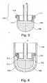
- Figure 6 schematically illustrates a cross section of the device along its longitudinal axis A.
- the duct 111 substantially has the shape of an inverted U, a first leg extending to the first chamber and a second leg extending to the second chamber.
- the duct 111 has a first opening 112 to the first chamber 103 and a second opening 113 to the second chamber 115.
- the openings 112, 113 are preferably ring-shaped.
- the U-shaped duct 111 may extend further into the second chamber 115 than into the first chamber 103.
- the arrows shown in Figure 6 adumbrate the path along which spermatozoa may travel from the first chamber 103 to the second chamber 115.
- the first, seminal fluid 135 may be received in the first chamber 103 formed at the lower end of the vessel 104. Since the first, seminal fluid may be, for example, semen of a patient, the provided volume may vary considerably.
- the displacement means 105 may be introduced into said first chamber 103 until the first, seminal fluid 135 is located proximate the first opening 112.
- the displacement means is inserted by a distance L into the first, seminal fluid.
- the upper surface of the first, seminal fluid is displaced a distance D towards the first opening 112 (see Figure 7B ).
- the first, seminal fluid 135 does not reach the first opening 112 entirely.
- a space S remains between the first, seminal fluid 135 and the first opening 112, which is subsequently covered by second fluid 136 flowing through the duct 111 when the second chamber 115 is filled.
- displacing the first, seminal fluid 135 to contact the first opening 112 may be considered for some applications.
- the space S between the first, seminal fluid 135 and the first opening 112 may be equalized for a broad range of volumes of first, seminal fluid provided in the first chamber 135 by inserting the displacement element 109 to the appropriate depth L. Since, the volume of second fluid 136 can be kept constant and reproducible results can be obtained.
- the second fluid for example, a buffer medium is subsequently provided in the second chamber 115.
- the second fluid preferably is drawn into the duct 111 by capillary action and/or due to the pressure exerted when filling it into the second chamber, for example, along the shaft 123 by means of a pipette.
- the duct 111 establishes a liquid bridge between the first chamber 103 and the second chamber 115, allowing spermatozoa to move along the path indicated by the arrows shown on Figures 6 and 7C .
- spermatozoa or other motile cells in the first fluid 135 will swim or flow from the first chamber through the duct 119 into second fluid 136 contained in the second chamber.
- the second fluid may be withdrawn from the second chamber, for example, by means of a pipette introduced through the shaft 123.
- the first chamber 103 may be sealed relative to the environment (e.g. by closing the open upper end of the vessel 104 with the plug 127, as shown in Figure 3A ) in order to prevent first, seminal fluid 135 from being drawn into the second chamber 115 when collecting the fluid contained therein.
- the sequence of the steps described above may be changed in embodiments of the invention.
- the second fluid 136 may be received in the second chamber 115 before the displacement means is introduced into the first chamber 103.
- the displacement means may be introduced into the first chamber before the first, seminal fluid 135 is received therein.
- the ring-shaped cover 119 preferably is located at least 0.1 mm, preferably at least 0.2 mm, and more preferably between 0.3 and 0.4 mm from the rim.
- the duct 111 preferably has a width of at least 0.1 mm, more preferably at least 0.2 mm and most preferably between 0.3 and 0.4 mm.
- the optimal widths will depend on the materials and the fluids employed, as both may influence capillary action.
- the length of the duct 111 preferably is between 15 to 40 mm, more preferably between 20 to 38 mm, most preferably between 25 to 35 mm as measured from the first opening to the second opening when considering a cross section of the displacement element along longitudinal axis B.
- the outer surface of the lower portion of the displacement means that is introduced into the first chamber may be shaped in different ways, for example in a substantially spherical, hemispherical, conical, truncated or cylindrical manner.
- the inner surface of the first chamber 103 in particular the inner surface of the closed lower end of the vessel 104 may have various shapes.
- the inner surface may be, inter alia, substantially hemispherical, conical, truncated or cylindrical.
- the above-mentioned shapes may be combined as desired.
- rounded displacement means may be used with conical vessels and vice-versa.
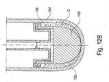
- FIGS 8A-8E illustrate different embodiments of displacement means for devices according to the present invention, the forms of which may also be combined.
- a gap G may be formed between the lower portion of the displacement means 105 and the interior wall of the vessel 104. More specifically, the gap G preferably is formed between the displacement element 109 and the vessel 104.
- the gap G may be variable.
- the gap G preferably is formed such that a relatively large fraction of the first, seminal fluid received in the first chamber is displaced from the bottom of the first chamber proximate the first opening of the duct.
- the gap G may provide an enlarged collection space proximate the first opening.
- the width of the gap G preferably increases from a lower part towards an upper part of the first chamber 103 when the displacement means 105 is fully inserted.
- the displacement element 109 may follow the inner surface of the first chamber at the bottom of the vessel 104 (i.e.
- the shape of the displacement element 109 may also match the shape of the lower end of the vessel 104.
- both elements may have a generally hemispherical ( Figure 8D ) or generally conical ( Figure 8E ) shape along at least their contacting segments.
- the displacement means 109 may have different sizes and displacement volumes, the displacement means 109 of Figures 8D and 8E being somewhat “shorter” along the longitudinal axis B. It should be noted that any of displacement means described above (e.g., the displacement means illustrated in Figures 8A-8E ) may be "shortened” or "elongated” in order to provide the displacement element 109 with a desired displacement volume and/or shape.
- the device may be provided with first and second scales. 129, 131 for assessing the volume of the first, seminal fluid provided in the first chamber and the travel of the displacement means relative to the vessel 104, respectively.
- the first scale 129 is provided on the vessel 104 and the second scale 131 is provided on the displacement means 105 (e.g., at an upper portion).
- the second scale may also be located on the vessel 104, for example, at an upper portion thereof. While the second scale 131 is described above as being located at the upper portion of the vessel 104 and the displacement means 105, it should be noted that the second scale may be located at any suitable height along the longitudinal axis of the device.
- the second scale 131 may indicate the travel required for the displacement means dependant upon the volume of first, seminal fluid provided in the first chamber. Users of the device will then be able to assess the volume of first, seminal fluid in the first chamber by means of the first scale and, subsequently, the travel required for the displacement means on the second scale without having to perform intermediate steps or calculations.
- the distance to which the displacement means has to be inserted will not be inversely proportional to the volume received in the first chamber but, for example, correlate in a somewhat reciprocal manner.
- the distance between adjacent gradations of the second sale 131 therefore may vary and, for example, become smaller for larger volumes.
- the same volume of second fluid may be required, irrespectively of the volume of first, seminal fluid received in the first chamber.
- the device 101 may also comprise a pipette 140.
- the pipette 140 may be adapted for being inserted into the shaft 123 and may contain a defined and/or fixed volume of second fluid 136, determined such that optimal wetting of the duct is ensured. Since the fluid level in the first chamber may be adjusted with the displacement means, this volume may be fixed, regardless of the volume of first, seminal fluid provided in the first chamber.
- the pipette 140 may be configured to inject the second fluid 136 at a predetermined speed and/or with a predetermined pressure in order to prevent formation of air bubbles in the second fluid 136.
- the device 101 and the pipette 140 may be provided as a kit.
- the closure means (e.g., plug 127) may be inserted into the first chamber 103 after sealing it therewith. More specifically, the closure means may be inserted into the vessel 104 after sealing it, for example, at its open upper end.
- the closure means may be configured such that they can be inserted a predetermined maximal depth into the vessel.
- the plug 227 has a lower portion with a first diameter and an upper portion with a second diameter that is larger than the first diameter. Therefore, an abutment surface is formed that abuts the upper end of the side wall of the vessel 104 and prevents further insertion of the plug when the maximal depth is reached.
- the illustrative embodiment further comprises an optional screw cap 228 that is provided with an inner thread 229 in order to engage an attachment means 106 of the vessel 104.
- the attachment means 106 may be formed by an outer thread formed on the outer surface of the vessel's wall.
- plugs e.g., a generally cylindrical plug having a diameter that corresponds to the inner diameter of the upper end of the vessel 104 may be employed. Such plugs may be affixed to the cap 228 or may be formed as separate components.
- the positive pressure caused by inserting the plug 127, 227 into the vessel 104 may push a fixed volume of second fluid 136 located along the inner part of the duct proximate the second opening into the second chamber.
- the vessel 104 may be sealed thereafter, so that no additional fluid is drawn into the second chamber when the fluid contained therein is extracted.
- FIG. 13A illustrates the funnel structure 170 of the present invention in an upright position, such that the funnel can be used to fill liquids into a receptacle or vessel.
- the funnel structure 170 has a first circumferential wall 171 and a second circumferential wall 172, which both taper towards the inside of the funnel structure 170 (i.e., towards its central axis) in a downward direction.
- the first circumferential wall 171 may form an outer funnel and the second circumferential wall may form an inner funnel with respect to said outer funnel.
- the inner and outer funnels may have generally conical shapes along at least a segment.
- the first and second circumferential walls may be connected by an upper wall 173.
- a recuperation compartment 179 is formed between the first and second circumferential walls.
- the upper end of the recuperation compartment may be closed by upper wall 173 and may be open in a downward direction when the funnel structure 170 is positioned in an upright manner.
- One, several or all of the walls of the funnel structure may be formed from polymeric materials or glass. The walls may be formed integrally.
- the funnel structure 170 comprises an inlet opening 175 and an outlet opening 177.
- the outlet opening 177 preferably has a smaller cross-sectional area than the inlet opening 175 and preferably is disposed below the inlet opening 175 when the funnel structure 170 is in the upright position, as shown in Figure 13A .
- An intermediate opening 176 may be disposed between the inlet opening 175 and the outlet opening 177.
- the inlet opening 175 is formed at the upper end of the second circumferential wall 172 and the intermediate opening 176 is formed at the lower end of the second circumferential wall 172.
- the outlet opening 177 preferably is formed at the lower end of the first circumferential wall 171.
- the funnel structure 170 may be provided with an attachment structure 174 for attaching the funnel to a vessel.
- the attachment structure 174 is provided on a cylindrical protrusion with an internal thread.
- the vessel 104 may be inserted into the cylindrical protrusion in order to prevent contamination of the vessel's inner walls.
- other types of connectors and/or attachment structures may be provided, as appropriate.
- the funnel structure may also comprise an optional air vent 178 that fluidly connects the interior of the vessel 104 and the environment.
- the air vent 178 provides a fluid connection between the interior of the vessel 104 and the recuperation compartment 179.
- the air vent 178 may be provided by a hole traversing the first circumferential wall 171.
- the funnel structure may be attached to the vessel 104 of the selection device and used in combination therewith.
- the vessel 104 may be provided with attachment means 106 for this purpose.
- the attachment means 106 may be configured to engage the attachment structure 174 of the funnel structure 170.
- the attachment means 106 may be provided proximate the upper opening of the vessel 104 according to embodiments of the invention.
- the vessel 104 may be inserted into a stand 180 in order to maintain it in an upright position or may be self standing.
- Figure 13B illustrates the functional principle of the funnel structure 170.
- the liquid e.g., the seminal fluid 135
- the vessel 104 and the funnel structure 170 are disposed in a horizontal position, knocked over or turned around, most or all of the liquid (e.g., the seminal fluid 135) that is contained in the vessel 104 and flows out through the outlet opening 177 of the funnel structure 170 is captured in the recuperation compartment 179. Therefore, contamination of the liquid flowing out of the vessel 104 is prevented and the liquid may be filled back into the vessel 104, e.g., by holding the funnel structure 170 and the vessel 104 in the upright manner shown in Figure 13A .
- the liquid e.g., the seminal fluid 135
- the attachment structure 174 preferably is configured to provide a leak-proof attachment with the vessel 104, such that, when the vessel 104 is disposed in a horizontal position, knocked over and/or turned upside-down, the liquid 135 remaining in the vessel 104 does not leak through the upper opening of the vessel 104.
- the vessel 104, the funnel structure 170 and/or the stand 180 may also be configured such that the vessel's bottom is below its opening when the vessel is knocked over and/or lies horizontally. In this case, a leak proof seal between the attachment structure 174 of the funnel structure 170 and the attachment means 106 of the vessel 104 may not be required.
- the present invention provides improved selection devices and methods that can be used with varying volumes of seminal fluid.
- the device may be used for seminal fluid volumes of less than 1 ml or less than 0.5 ml without requiring dilution.
- the time required for separating such sperm samples may be reduced significantly, thereby decreasing chemical stress due to contact with atmospheric O 2 . Further, less handling steps are required and mechanical stress is reduced also.
- the first chamber may be sealed relative to the environment, contamination of the collected sample by spermatozoa with strand breaks and/or low motility is presented. Moreover, exposure of spermatozoa to oxygen before, during and/or after the selection procedure is reduced further.
- the same amount of medium may be used irrespectively of the volume of seminal fluid received in the first chamber.
- handling of the device is simplified and repeatable results are obtained more easily.
- Wetting of the fluid connection is improved, e.g., when using the pipette described above for injecting the medium, which may also lead to better results when performing the selection procedure.
Landscapes
- Health & Medical Sciences (AREA)
- Life Sciences & Earth Sciences (AREA)
- Engineering & Computer Science (AREA)
- Chemical & Material Sciences (AREA)
- Biomedical Technology (AREA)
- Organic Chemistry (AREA)
- Bioinformatics & Cheminformatics (AREA)
- Wood Science & Technology (AREA)
- Zoology (AREA)
- Genetics & Genomics (AREA)
- General Health & Medical Sciences (AREA)
- Biochemistry (AREA)
- Biotechnology (AREA)
- Physics & Mathematics (AREA)
- Microbiology (AREA)
- General Engineering & Computer Science (AREA)
- Analytical Chemistry (AREA)
- Molecular Biology (AREA)
- Cell Biology (AREA)
- Sustainable Development (AREA)
- Hematology (AREA)
- Clinical Laboratory Science (AREA)
- Chemical Kinetics & Catalysis (AREA)
- Optics & Photonics (AREA)
- Biophysics (AREA)
- Urology & Nephrology (AREA)
- Food Science & Technology (AREA)
- Medicinal Chemistry (AREA)
- General Physics & Mathematics (AREA)
- Immunology (AREA)
- Pathology (AREA)
- Developmental Biology & Embryology (AREA)
- Apparatus Associated With Microorganisms And Enzymes (AREA)
- External Artificial Organs (AREA)
Claims (16)
- Dispositif (101) pour la sélection de spermatozoïdes, comprenant :un premier compartiment (103) prévu pour recevoir un premier fluide séminal (135), etun deuxième compartiment (115) prévu pour recevoir un deuxième fluide (136), le deuxième compartiment (115) étant en communication fluidique avec le premier compartiment (103) par au moins un conduit (111) présentant une première ouverture (112) vers le premier compartiment (103) et une deuxième ouverture (113) vers le deuxième compartiment,ledit dispositif étant caractérisé en ce qu'il comprend en outreun moyen de refoulement (105) avec un corps de refoulement (109) prévu pour refouler au moins une partie du premier fluide séminal (135) vers la première ouverture (112).
- Dispositif selon la revendication 1, où le premier compartiment est réalisé par un récipient avec une extrémité inférieure fermée, préférentiellement un récipient tubulaire.
- Dispositif selon la revendication 1 ou la revendication 2, où le moyen de refoulement est logé de manière coulissante dans le premier compartiment.
- Dispositif selon la revendication 1, la revendication 2 ou la revendication 3, où le moyen de refoulement est apte à refouler le premier fluide séminal de manière à placer la surface supérieure du premier fluide séminal à une distance définie de la première ouverture.
- Dispositif selon la revendication 2, où une partie inférieure du moyen de refoulement a une forme extérieure sensiblement ajustée à la forme intérieure de l'extrémité inférieure fermée du récipient.
- Dispositif selon la revendication 2, où un interstice variable est formé entre le moyen de refoulement et le récipient, la grandeur dudit interstice augmentant préférentiellement d'une partie inférieure du premier compartiment vers une partie supérieure du premier compartiment en position d'introduction complète du moyen de refoulement.
- Dispositif selon l'une des revendications précédentes, où le moyen de refoulement comprend en outre une tige pour la manipulation dudit moyen de refoulement.
- Dispositif selon l'une des revendications précédentes, où le deuxième compartiment est formé dans le moyen de refoulement.
- Dispositif selon la revendication 7 ou la revendication 8, où la tige est creuse et est ouverte vers le deuxième compartiment.
- Dispositif selon l'une des revendications précédentes, où le conduit a une section transversale en forme de U inversé, une première branche du U s'étendant vers le premier compartiment et une deuxième branche du U s'étendant vers le deuxième compartiment.
- Dispositif selon l'une des revendications précédentes, où le corps de refoulement comprend un rebord s'étendant vers le haut et où la tige est raccordée à un couvercle en forme d'anneau, le conduit étant formé entre le rebord et le couvercle.
- Dispositif selon l'une des revendications précédentes, où le récipient est pourvu d'une première graduation pour évaluer un volume du premier fluide séminal dans le premier compartiment.
- Dispositif selon l'une des revendications précédentes, comprenant une deuxième graduation pour évaluer la course du moyen de refoulement.
- Dispositif selon les revendications 12 et 13, où la deuxième graduation indique la course du moyen de refoulement exigée en fonction du volume indiqué par la première graduation.
- Dispositif selon l'une des revendications précédentes, comprenant en outre un moyen de fermeture pour rendre le premier compartiment étanche à l'environnement.
- Procédé de sélection de cellules mobiles recourant au dispositif (101) selon la revendication 1, comprenant les étapes de :(a) préparation d'un premier fluide (135) comprenant des cellules mobiles dans le premier compartiment (103) ;(b) préparation d'un milieu tampon (136) dans le deuxième compartiment (115) ; et(c) réalisation d'une jonction par liaison liquide entre le premier compartiment (103) et le deuxième compartiment (115) ; et(d) refoulement d'au moins une partie du premier fluide (135) vers, à proximité ou jusqu'à la première ouverture (112) du conduit (111) au moyen du corps de refoulement (109).
Priority Applications (8)
| Application Number | Priority Date | Filing Date | Title |
|---|---|---|---|
| ES12174599T ES2571532T3 (es) | 2012-07-02 | 2012-07-02 | Dispositivo para la selección de espermatozoides |
| EP12174599.6A EP2682747B1 (fr) | 2012-07-02 | 2012-07-02 | Dispositif de sélection de spermatozoides |
| PCT/EP2013/063932 WO2014006043A2 (fr) | 2012-07-02 | 2013-07-02 | Dispositif de sélection |
| AU2013285517A AU2013285517B2 (en) | 2012-07-02 | 2013-07-02 | Device for spermatozoa selection |
| EP13744450.1A EP2872889B1 (fr) | 2012-07-02 | 2013-07-02 | Dispositif de sélection de spermatozoides |
| ES13744450.1T ES2623509T3 (es) | 2012-07-02 | 2013-07-02 | Dispositivo para la selección de espermatozoides |
| US14/411,863 US9606099B2 (en) | 2012-07-02 | 2013-07-02 | Selection device |
| DK13744450.1T DK2872889T3 (en) | 2012-07-02 | 2013-07-02 | Device for selection of spermatozoa |
Applications Claiming Priority (1)
| Application Number | Priority Date | Filing Date | Title |
|---|---|---|---|
| EP12174599.6A EP2682747B1 (fr) | 2012-07-02 | 2012-07-02 | Dispositif de sélection de spermatozoides |
Publications (2)
| Publication Number | Publication Date |
|---|---|
| EP2682747A1 EP2682747A1 (fr) | 2014-01-08 |
| EP2682747B1 true EP2682747B1 (fr) | 2016-02-24 |
Family
ID=48914222
Family Applications (2)
| Application Number | Title | Priority Date | Filing Date |
|---|---|---|---|
| EP12174599.6A Not-in-force EP2682747B1 (fr) | 2012-07-02 | 2012-07-02 | Dispositif de sélection de spermatozoides |
| EP13744450.1A Not-in-force EP2872889B1 (fr) | 2012-07-02 | 2013-07-02 | Dispositif de sélection de spermatozoides |
Family Applications After (1)
| Application Number | Title | Priority Date | Filing Date |
|---|---|---|---|
| EP13744450.1A Not-in-force EP2872889B1 (fr) | 2012-07-02 | 2013-07-02 | Dispositif de sélection de spermatozoides |
Country Status (6)
| Country | Link |
|---|---|
| US (1) | US9606099B2 (fr) |
| EP (2) | EP2682747B1 (fr) |
| AU (1) | AU2013285517B2 (fr) |
| DK (1) | DK2872889T3 (fr) |
| ES (2) | ES2571532T3 (fr) |
| WO (1) | WO2014006043A2 (fr) |
Families Citing this family (4)
| Publication number | Priority date | Publication date | Assignee | Title |
|---|---|---|---|---|
| DE102015116391B4 (de) | 2015-09-28 | 2017-04-27 | Marion Vollmer | Medizinische Vorrichtung für die selektive Separierung einer biologischen Probe |
| EP3577208A4 (fr) | 2017-01-31 | 2020-12-02 | Genea IP Holdings Pty Limited | Procédé et système de traitement d'un échantillon biologique |
| EP4362812B1 (fr) * | 2021-06-30 | 2025-07-09 | RSI Technology Group, LLC | Appareil pour la collecte d'échantillons de fluide |
| CN115960715A (zh) * | 2021-10-09 | 2023-04-14 | 深圳拜尔洛克生物技术有限公司 | 一种自动化精子处理装置及方法 |
Family Cites Families (10)
| Publication number | Priority date | Publication date | Assignee | Title |
|---|---|---|---|---|
| US3659749A (en) * | 1970-04-28 | 1972-05-02 | Boris Schwartz | Intermixing syringe |
| US4557899A (en) * | 1984-10-15 | 1985-12-10 | Hach Company | Water-in-oil testing apparatus |
| US5686302A (en) | 1993-02-09 | 1997-11-11 | Zech; Josef | Device for removing sperm cells form seminal fluid |
| US5866354A (en) * | 1996-12-16 | 1999-02-02 | The State Of Oregon Acting By And Through The State Of Board Of Higher Education On Behalf Of Oregon State University | Method for measuring mobility of sperm |
| GB9817795D0 (en) * | 1998-08-14 | 1998-10-14 | Genosis Inc | A method and device for separation and detection of spermatozoa in a sample |
| GB0003596D0 (en) * | 2000-02-16 | 2000-04-05 | Genosis Ltd | Sperm separation |
| AT410280B (de) | 2001-10-05 | 2003-03-25 | Zech Josef Dr | Einrichtung zur gewinnung von samenzellen aus samenflüssigkeit |
| AU2002360273A1 (en) | 2001-10-11 | 2003-04-22 | Genome Therapeutics Corporation | Nucleotide and amino acid sequences relating to respiratory diseases and obesity |
| US8535622B2 (en) * | 2009-04-22 | 2013-09-17 | Lotus Bio (Nymphaea) Ltd | Sperm separation system |
| WO2012032165A1 (fr) | 2010-09-09 | 2012-03-15 | Josef Zech | Procédé d'enrichissement en spermatozoïdes sans cassure des brins d'adn et réduction des risques d'anomalies et/ou d'aneuploïdie |
-
2012
- 2012-07-02 EP EP12174599.6A patent/EP2682747B1/fr not_active Not-in-force
- 2012-07-02 ES ES12174599T patent/ES2571532T3/es active Active
-
2013
- 2013-07-02 WO PCT/EP2013/063932 patent/WO2014006043A2/fr not_active Ceased
- 2013-07-02 EP EP13744450.1A patent/EP2872889B1/fr not_active Not-in-force
- 2013-07-02 DK DK13744450.1T patent/DK2872889T3/en active
- 2013-07-02 AU AU2013285517A patent/AU2013285517B2/en not_active Ceased
- 2013-07-02 ES ES13744450.1T patent/ES2623509T3/es active Active
- 2013-07-02 US US14/411,863 patent/US9606099B2/en active Active
Also Published As
| Publication number | Publication date |
|---|---|
| EP2872889A2 (fr) | 2015-05-20 |
| US20150192561A1 (en) | 2015-07-09 |
| DK2872889T3 (en) | 2017-05-08 |
| EP2682747A1 (fr) | 2014-01-08 |
| WO2014006043A2 (fr) | 2014-01-09 |
| WO2014006043A3 (fr) | 2014-02-27 |
| AU2013285517B2 (en) | 2017-04-13 |
| EP2872889B1 (fr) | 2017-02-15 |
| US9606099B2 (en) | 2017-03-28 |
| ES2623509T3 (es) | 2017-07-11 |
| ES2571532T3 (es) | 2016-05-25 |
| AU2013285517A1 (en) | 2015-01-29 |
Similar Documents
| Publication | Publication Date | Title |
|---|---|---|
| US12013321B2 (en) | Biological fluid collection device and collection module | |
| CA2954658C (fr) | Dispositif de gestion de micro-echantillons de fluides biologiques | |
| US9696242B2 (en) | Fixed chamber separator with adjustment withdrawal member | |
| ES2877598T3 (es) | Tapón perforable comoldeado y método para fabricar el mismo | |
| EP2682747B1 (fr) | Dispositif de sélection de spermatozoides | |
| JP2012509489A (ja) | 初尿採取器 | |
| KR20180083442A (ko) | 시료를 수집 및 주입하기 위한 장치 | |
| CN104780848A (zh) | 尿收集和分析设备 | |
| KR101862988B1 (ko) | 다단계 분리형 검체 수송 및 반응용기 | |
| KR102043955B1 (ko) | 검체 채취용 어댑터 | |
| US9730678B2 (en) | Collecting a urine sample | |
| AU2024204132A1 (en) | Biological fluid micro-sample management device | |
| WO2009018521A1 (fr) | Appareil et procédé de séparation et de stockage de matériau reproductif dans un réservoir cryogénique | |
| AU2011205088A1 (en) | System and method for dispensing fluid from a container and into a fluid receptacle | |
| US20140332477A1 (en) | Apparatus to Dispense Immiscible Liquid from an Inverted Bottle | |
| CA3091677C (fr) | Dispositif de collecte de liquide biologique et module de collecte | |
| US20160030940A1 (en) | Device for standard preparation of urinary sediment for urine analysis (Mono System) | |
| CN103960225A (zh) | 一种双杯体标本保存杯 |
Legal Events
| Date | Code | Title | Description |
|---|---|---|---|
| PUAI | Public reference made under article 153(3) epc to a published international application that has entered the european phase |
Free format text: ORIGINAL CODE: 0009012 |
|
| AK | Designated contracting states |
Kind code of ref document: A1 Designated state(s): AL AT BE BG CH CY CZ DE DK EE ES FI FR GB GR HR HU IE IS IT LI LT LU LV MC MK MT NL NO PL PT RO RS SE SI SK SM TR |
|
| AX | Request for extension of the european patent |
Extension state: BA ME |
|
| 17P | Request for examination filed |
Effective date: 20140708 |
|
| RBV | Designated contracting states (corrected) |
Designated state(s): AL AT BE BG CH CY CZ DE DK EE ES FI FR GB GR HR HU IE IS IT LI LT LU LV MC MK MT NL NO PL PT RO RS SE SI SK SM TR |
|
| REG | Reference to a national code |
Ref country code: DE Ref legal event code: R079 Ref document number: 602012014850 Country of ref document: DE Free format text: PREVIOUS MAIN CLASS: G01N0033500000 Ipc: C12M0001000000 |
|
| GRAP | Despatch of communication of intention to grant a patent |
Free format text: ORIGINAL CODE: EPIDOSNIGR1 |
|
| RIC1 | Information provided on ipc code assigned before grant |
Ipc: C12N 5/071 20100101ALI20150219BHEP Ipc: C12M 1/00 20060101AFI20150219BHEP Ipc: G01N 33/50 20060101ALI20150219BHEP |
|
| INTG | Intention to grant announced |
Effective date: 20150306 |
|
| GRAP | Despatch of communication of intention to grant a patent |
Free format text: ORIGINAL CODE: EPIDOSNIGR1 |
|
| INTG | Intention to grant announced |
Effective date: 20150708 |
|
| GRAS | Grant fee paid |
Free format text: ORIGINAL CODE: EPIDOSNIGR3 |
|
| INTG | Intention to grant announced |
Effective date: 20151214 |
|
| GRAA | (expected) grant |
Free format text: ORIGINAL CODE: 0009210 |
|
| AK | Designated contracting states |
Kind code of ref document: B1 Designated state(s): AL AT BE BG CH CY CZ DE DK EE ES FI FR GB GR HR HU IE IS IT LI LT LU LV MC MK MT NL NO PL PT RO RS SE SI SK SM TR |
|
| REG | Reference to a national code |
Ref country code: GB Ref legal event code: FG4D |
|
| REG | Reference to a national code |
Ref country code: CH Ref legal event code: EP |
|
| REG | Reference to a national code |
Ref country code: AT Ref legal event code: REF Ref document number: 776759 Country of ref document: AT Kind code of ref document: T Effective date: 20160315 |
|
| REG | Reference to a national code |
Ref country code: IE Ref legal event code: FG4D |
|
| REG | Reference to a national code |
Ref country code: DE Ref legal event code: R096 Ref document number: 602012014850 Country of ref document: DE |
|
| REG | Reference to a national code |
Ref country code: SE Ref legal event code: TRGR |
|
| REG | Reference to a national code |
Ref country code: ES Ref legal event code: FG2A Ref document number: 2571532 Country of ref document: ES Kind code of ref document: T3 Effective date: 20160525 Ref country code: NL Ref legal event code: FP |
|
| REG | Reference to a national code |
Ref country code: LT Ref legal event code: MG4D |
|
| REG | Reference to a national code |
Ref country code: CH Ref legal event code: NV Representative=s name: VOSSIUS AND PARTNER PATENTANWAELTE RECHTSANWAE, CH |
|
| REG | Reference to a national code |
Ref country code: FR Ref legal event code: PLFP Year of fee payment: 5 |
|
| PG25 | Lapsed in a contracting state [announced via postgrant information from national office to epo] |
Ref country code: HR Free format text: LAPSE BECAUSE OF FAILURE TO SUBMIT A TRANSLATION OF THE DESCRIPTION OR TO PAY THE FEE WITHIN THE PRESCRIBED TIME-LIMIT Effective date: 20160224 Ref country code: GR Free format text: LAPSE BECAUSE OF FAILURE TO SUBMIT A TRANSLATION OF THE DESCRIPTION OR TO PAY THE FEE WITHIN THE PRESCRIBED TIME-LIMIT Effective date: 20160525 Ref country code: FI Free format text: LAPSE BECAUSE OF FAILURE TO SUBMIT A TRANSLATION OF THE DESCRIPTION OR TO PAY THE FEE WITHIN THE PRESCRIBED TIME-LIMIT Effective date: 20160224 Ref country code: NO Free format text: LAPSE BECAUSE OF FAILURE TO SUBMIT A TRANSLATION OF THE DESCRIPTION OR TO PAY THE FEE WITHIN THE PRESCRIBED TIME-LIMIT Effective date: 20160524 |
|
| PG25 | Lapsed in a contracting state [announced via postgrant information from national office to epo] |
Ref country code: PT Free format text: LAPSE BECAUSE OF FAILURE TO SUBMIT A TRANSLATION OF THE DESCRIPTION OR TO PAY THE FEE WITHIN THE PRESCRIBED TIME-LIMIT Effective date: 20160624 Ref country code: LV Free format text: LAPSE BECAUSE OF FAILURE TO SUBMIT A TRANSLATION OF THE DESCRIPTION OR TO PAY THE FEE WITHIN THE PRESCRIBED TIME-LIMIT Effective date: 20160224 Ref country code: LT Free format text: LAPSE BECAUSE OF FAILURE TO SUBMIT A TRANSLATION OF THE DESCRIPTION OR TO PAY THE FEE WITHIN THE PRESCRIBED TIME-LIMIT Effective date: 20160224 Ref country code: RS Free format text: LAPSE BECAUSE OF FAILURE TO SUBMIT A TRANSLATION OF THE DESCRIPTION OR TO PAY THE FEE WITHIN THE PRESCRIBED TIME-LIMIT Effective date: 20160224 Ref country code: PL Free format text: LAPSE BECAUSE OF FAILURE TO SUBMIT A TRANSLATION OF THE DESCRIPTION OR TO PAY THE FEE WITHIN THE PRESCRIBED TIME-LIMIT Effective date: 20160224 |
|
| PG25 | Lapsed in a contracting state [announced via postgrant information from national office to epo] |
Ref country code: DK Free format text: LAPSE BECAUSE OF FAILURE TO SUBMIT A TRANSLATION OF THE DESCRIPTION OR TO PAY THE FEE WITHIN THE PRESCRIBED TIME-LIMIT Effective date: 20160224 Ref country code: EE Free format text: LAPSE BECAUSE OF FAILURE TO SUBMIT A TRANSLATION OF THE DESCRIPTION OR TO PAY THE FEE WITHIN THE PRESCRIBED TIME-LIMIT Effective date: 20160224 |
|
| REG | Reference to a national code |
Ref country code: DE Ref legal event code: R097 Ref document number: 602012014850 Country of ref document: DE |
|
| PG25 | Lapsed in a contracting state [announced via postgrant information from national office to epo] |
Ref country code: SM Free format text: LAPSE BECAUSE OF FAILURE TO SUBMIT A TRANSLATION OF THE DESCRIPTION OR TO PAY THE FEE WITHIN THE PRESCRIBED TIME-LIMIT Effective date: 20160224 Ref country code: RO Free format text: LAPSE BECAUSE OF FAILURE TO SUBMIT A TRANSLATION OF THE DESCRIPTION OR TO PAY THE FEE WITHIN THE PRESCRIBED TIME-LIMIT Effective date: 20160224 Ref country code: CZ Free format text: LAPSE BECAUSE OF FAILURE TO SUBMIT A TRANSLATION OF THE DESCRIPTION OR TO PAY THE FEE WITHIN THE PRESCRIBED TIME-LIMIT Effective date: 20160224 Ref country code: SK Free format text: LAPSE BECAUSE OF FAILURE TO SUBMIT A TRANSLATION OF THE DESCRIPTION OR TO PAY THE FEE WITHIN THE PRESCRIBED TIME-LIMIT Effective date: 20160224 |
|
| PLBE | No opposition filed within time limit |
Free format text: ORIGINAL CODE: 0009261 |
|
| STAA | Information on the status of an ep patent application or granted ep patent |
Free format text: STATUS: NO OPPOSITION FILED WITHIN TIME LIMIT |
|
| 26N | No opposition filed |
Effective date: 20161125 |
|
| PG25 | Lapsed in a contracting state [announced via postgrant information from national office to epo] |
Ref country code: BG Free format text: LAPSE BECAUSE OF FAILURE TO SUBMIT A TRANSLATION OF THE DESCRIPTION OR TO PAY THE FEE WITHIN THE PRESCRIBED TIME-LIMIT Effective date: 20160524 Ref country code: SI Free format text: LAPSE BECAUSE OF FAILURE TO SUBMIT A TRANSLATION OF THE DESCRIPTION OR TO PAY THE FEE WITHIN THE PRESCRIBED TIME-LIMIT Effective date: 20160224 |
|
| PG25 | Lapsed in a contracting state [announced via postgrant information from national office to epo] |
Ref country code: MC Free format text: LAPSE BECAUSE OF FAILURE TO SUBMIT A TRANSLATION OF THE DESCRIPTION OR TO PAY THE FEE WITHIN THE PRESCRIBED TIME-LIMIT Effective date: 20160224 |
|
| REG | Reference to a national code |
Ref country code: IE Ref legal event code: MM4A |
|
| REG | Reference to a national code |
Ref country code: FR Ref legal event code: PLFP Year of fee payment: 6 |
|
| PG25 | Lapsed in a contracting state [announced via postgrant information from national office to epo] |
Ref country code: IE Free format text: LAPSE BECAUSE OF NON-PAYMENT OF DUE FEES Effective date: 20160702 |
|
| PG25 | Lapsed in a contracting state [announced via postgrant information from national office to epo] |
Ref country code: LU Free format text: LAPSE BECAUSE OF NON-PAYMENT OF DUE FEES Effective date: 20160702 |
|
| REG | Reference to a national code |
Ref country code: AT Ref legal event code: UEP Ref document number: 776759 Country of ref document: AT Kind code of ref document: T Effective date: 20160224 |
|
| PG25 | Lapsed in a contracting state [announced via postgrant information from national office to epo] |
Ref country code: HU Free format text: LAPSE BECAUSE OF FAILURE TO SUBMIT A TRANSLATION OF THE DESCRIPTION OR TO PAY THE FEE WITHIN THE PRESCRIBED TIME-LIMIT; INVALID AB INITIO Effective date: 20120702 Ref country code: CY Free format text: LAPSE BECAUSE OF FAILURE TO SUBMIT A TRANSLATION OF THE DESCRIPTION OR TO PAY THE FEE WITHIN THE PRESCRIBED TIME-LIMIT Effective date: 20160224 |
|
| PG25 | Lapsed in a contracting state [announced via postgrant information from national office to epo] |
Ref country code: TR Free format text: LAPSE BECAUSE OF FAILURE TO SUBMIT A TRANSLATION OF THE DESCRIPTION OR TO PAY THE FEE WITHIN THE PRESCRIBED TIME-LIMIT Effective date: 20160224 Ref country code: MT Free format text: LAPSE BECAUSE OF NON-PAYMENT OF DUE FEES Effective date: 20160731 Ref country code: IS Free format text: LAPSE BECAUSE OF FAILURE TO SUBMIT A TRANSLATION OF THE DESCRIPTION OR TO PAY THE FEE WITHIN THE PRESCRIBED TIME-LIMIT Effective date: 20160224 Ref country code: MK Free format text: LAPSE BECAUSE OF FAILURE TO SUBMIT A TRANSLATION OF THE DESCRIPTION OR TO PAY THE FEE WITHIN THE PRESCRIBED TIME-LIMIT Effective date: 20160224 |
|
| REG | Reference to a national code |
Ref country code: FR Ref legal event code: PLFP Year of fee payment: 7 |
|
| PG25 | Lapsed in a contracting state [announced via postgrant information from national office to epo] |
Ref country code: AL Free format text: LAPSE BECAUSE OF FAILURE TO SUBMIT A TRANSLATION OF THE DESCRIPTION OR TO PAY THE FEE WITHIN THE PRESCRIBED TIME-LIMIT Effective date: 20160224 |
|
| PGFP | Annual fee paid to national office [announced via postgrant information from national office to epo] |
Ref country code: NL Payment date: 20210720 Year of fee payment: 10 |
|
| PGFP | Annual fee paid to national office [announced via postgrant information from national office to epo] |
Ref country code: AT Payment date: 20210726 Year of fee payment: 10 Ref country code: FR Payment date: 20210719 Year of fee payment: 10 Ref country code: IT Payment date: 20210716 Year of fee payment: 10 |
|
| PGFP | Annual fee paid to national office [announced via postgrant information from national office to epo] |
Ref country code: ES Payment date: 20210817 Year of fee payment: 10 Ref country code: GB Payment date: 20210728 Year of fee payment: 10 Ref country code: SE Payment date: 20210716 Year of fee payment: 10 Ref country code: BE Payment date: 20210720 Year of fee payment: 10 Ref country code: CH Payment date: 20210728 Year of fee payment: 10 Ref country code: DE Payment date: 20210730 Year of fee payment: 10 |
|
| REG | Reference to a national code |
Ref country code: DE Ref legal event code: R119 Ref document number: 602012014850 Country of ref document: DE |
|
| REG | Reference to a national code |
Ref country code: CH Ref legal event code: PL Ref country code: SE Ref legal event code: EUG |
|
| REG | Reference to a national code |
Ref country code: NL Ref legal event code: MM Effective date: 20220801 |
|
| REG | Reference to a national code |
Ref country code: AT Ref legal event code: MM01 Ref document number: 776759 Country of ref document: AT Kind code of ref document: T Effective date: 20220702 |
|
| GBPC | Gb: european patent ceased through non-payment of renewal fee |
Effective date: 20220702 |
|
| REG | Reference to a national code |
Ref country code: BE Ref legal event code: MM Effective date: 20220731 |
|
| PG25 | Lapsed in a contracting state [announced via postgrant information from national office to epo] |
Ref country code: SE Free format text: LAPSE BECAUSE OF NON-PAYMENT OF DUE FEES Effective date: 20220703 Ref country code: LI Free format text: LAPSE BECAUSE OF NON-PAYMENT OF DUE FEES Effective date: 20220731 Ref country code: FR Free format text: LAPSE BECAUSE OF NON-PAYMENT OF DUE FEES Effective date: 20220731 Ref country code: CH Free format text: LAPSE BECAUSE OF NON-PAYMENT OF DUE FEES Effective date: 20220731 Ref country code: AT Free format text: LAPSE BECAUSE OF NON-PAYMENT OF DUE FEES Effective date: 20220702 |
|
| PG25 | Lapsed in a contracting state [announced via postgrant information from national office to epo] |
Ref country code: GB Free format text: LAPSE BECAUSE OF NON-PAYMENT OF DUE FEES Effective date: 20220702 Ref country code: DE Free format text: LAPSE BECAUSE OF NON-PAYMENT OF DUE FEES Effective date: 20230201 Ref country code: BE Free format text: LAPSE BECAUSE OF NON-PAYMENT OF DUE FEES Effective date: 20220731 |
|
| PG25 | Lapsed in a contracting state [announced via postgrant information from national office to epo] |
Ref country code: NL Free format text: LAPSE BECAUSE OF NON-PAYMENT OF DUE FEES Effective date: 20220801 |
|
| PG25 | Lapsed in a contracting state [announced via postgrant information from national office to epo] |
Ref country code: IT Free format text: LAPSE BECAUSE OF NON-PAYMENT OF DUE FEES Effective date: 20220702 |
|
| REG | Reference to a national code |
Ref country code: ES Ref legal event code: FD2A Effective date: 20230829 |
|
| PG25 | Lapsed in a contracting state [announced via postgrant information from national office to epo] |
Ref country code: ES Free format text: LAPSE BECAUSE OF NON-PAYMENT OF DUE FEES Effective date: 20220703 |