EP2683036A1 - Boîtier de connexion destiné à loger au moins partiellement un élément connecteur de boîtier et agencement de connecteur à fiches destiné à relier entre eux un élément de contact mâle et un élément de contact femelle - Google Patents
Boîtier de connexion destiné à loger au moins partiellement un élément connecteur de boîtier et agencement de connecteur à fiches destiné à relier entre eux un élément de contact mâle et un élément de contact femelle Download PDFInfo
- Publication number
- EP2683036A1 EP2683036A1 EP13173022.8A EP13173022A EP2683036A1 EP 2683036 A1 EP2683036 A1 EP 2683036A1 EP 13173022 A EP13173022 A EP 13173022A EP 2683036 A1 EP2683036 A1 EP 2683036A1
- Authority
- EP
- European Patent Office
- Prior art keywords
- contact element
- recess
- plug housing
- male
- housing
- Prior art date
- Legal status (The legal status is an assumption and is not a legal conclusion. Google has not performed a legal analysis and makes no representation as to the accuracy of the status listed.)
- Granted
Links
Images


Classifications
-
- H—ELECTRICITY
- H01—ELECTRIC ELEMENTS
- H01R—ELECTRICALLY-CONDUCTIVE CONNECTIONS; STRUCTURAL ASSOCIATIONS OF A PLURALITY OF MUTUALLY-INSULATED ELECTRICAL CONNECTING ELEMENTS; COUPLING DEVICES; CURRENT COLLECTORS
- H01R12/00—Structural associations of a plurality of mutually-insulated electrical connecting elements, specially adapted for printed circuits, e.g. printed circuit boards [PCB], flat or ribbon cables, or like generally planar structures, e.g. terminal strips, terminal blocks; Coupling devices specially adapted for printed circuits, flat or ribbon cables, or like generally planar structures; Terminals specially adapted for contact with, or insertion into, printed circuits, flat or ribbon cables, or like generally planar structures
- H01R12/70—Coupling devices
- H01R12/7088—Arrangements for power supply
Definitions
- Plug housing for at least partially receiving a Gesimouseinsteckbauteils and electrical connector assembly for joining together a male contact element and a female contact element
- the invention relates to a plug housing for at least partially receiving a GeHouseinsteckbauteils and an electrical connector assembly for connecting a male contact element and a female contact element.
- male contact elements of the housing components In order to ensure the finger touch safety even in a non-nested state of the electrical connector assembly, it is necessary to cover freely accessible current-conducting, male contact elements of the housing components accordingly. This can be achieved, for example, by snapping or gluing a cap made of an electrically insulating material onto a male contact element of the electrical plug connection arrangement designed as, for example, a contact pin. This kind of cover the male However, contact elements can be cumbersome and time-consuming.
- connection of the housing components of the electrical connector assembly may be difficult, since the male contact element is no longer freely accessible due to the attached cap for making an electrically conductive connection between a male contact element and a female contact element female contact element of the electrical connector assembly.
- a plug housing for at least partially receiving a Gepatiuseinsteckbauteils with the features of claim 1 and an electrical connector assembly for joining together a male contact element and a female contact element with the features of claim 8.
- Advantageous embodiments of the invention are in the Subclaims specified.
- a plug housing for at least partially receiving a Gekoruseinsteckbauteils is provided, wherein a female contact element in the
- Housing insertion member is arranged, comprising a base body having a recess and a disposed in a bottom wall of the recess passage opening, wherein the through hole extends through the base body, wherein a portion of a male contact element through the through hole into the recess can be inserted, and a bow-shaped abutment member which is disposed adjacent to the through hole in the recess and protrudes into the recess, such that the portion of the male contact element can be applied to a side facing the passage opening side of the bow-shaped abutment element.
- male contact element may refer to a projecting, freely accessible electrically conductive element.
- female contact element may denote an electrically conductive element which may have a receptacle for receiving a male contact element.
- the plug-in housing according to the invention is based on the concept of permanently covering an outwardly facing end face of an exposed male contact element by means of a contact element arranged in particular in alignment with the passage opening of the plug-in housing.
- a FingerberlickSystem or generally safe handling of the plug housing can be ensured because the end face of the male contact element in a non-nested state of the plug housing and the Gesimouseinsteckbauteils can not be freely accessible and accidental contact of the male contact element is prevented at this end face.
- a freely accessible cross-section of the recess can be made by providing the Can be reduced contact element in a mating face of the plug housing, so that the dangers of passing past the contact element and a lateral contact of the male contact element can be reduced.
- the contact safety of the plug-in housing can be accomplished particularly simply and cost-effectively, since no additional cap of electrically insulating material is required to cover the male contact element.
- the handling of the plug housing and the electrical connector assembly may be simplified in their use, since the plug housing and the Genzouseeinsteckbauteil can be plugged into each other without further measures.
- the female contact element can be connectable to a first conductor arrangement and / or the male contact element can be connectable to a second conductor arrangement, so that a corresponding electrical contacting of both conductor arrangements via the male and female contact element can be made possible.
- the female contact element may be part of the first conductor arrangement and / or the male contact element may be part of the second conductor arrangement.
- the abutment member may be formed substantially U-shaped, wherein leg ends of legs of the abutment member may be connected to the bottom wall of the recess adjacent to an edge portion of an edge of the through hole.
- the legs of the contact element can be at least partially, for example, along a longitudinal extent of the legs, partially or completely connected to opposite side walls of the recess. Therefore, the contact element can be particularly stable and firmly connected to the base body, so that accidental bending or breaking of the contact element can be prevented. Furthermore, as viewed in the longitudinal direction of the contact element, a freely accessible cross-section of the recess can be reduced, so that the contact safety of the plug-in housing can be particularly large.
- the recess can be designed in the shape of a chamber with a substantially rectangular cross section, wherein the bow-shaped contact element can be arranged centrally in the recess.
- the plug housing may further comprise a web-shaped reinforcing element, which may be arranged in the recess and may extend transversely, in particular perpendicular, to the contact element, wherein the reinforcing element may connect the contact element with a side wall of the recess.
- the reinforcing element may be formed as a rib or rib-shaped.
- the reinforcing element may be connected to the bottom wall.
- a reinforcing element can be provided on each side of the contact element.
- the base body, the contact element and / or the reinforcing element may be integrally formed and / or may comprise or be formed from electrically insulating material, in particular plastic.
- the plug housing can be made particularly simple and therefore cost-effective. The production of the main body, the contact element and / or the reinforcing element made of electrically insulating material can prevent an electrically conductive connection of the male contact element via adjacent components.
- At least one further section of the male contact element can be received in a form-fitting manner in the passage opening and / or the section of the contact element can rest positively on the inner side of the contact element, so that inadvertent release of the male contact element from or from the plug housing can be prevented.
- the male contact element may comprise a contact blade or be formed as a contact blade and the passage opening may have an elongated cross-section.
- the terms "contact knife” or “knife contact” may each denote an end portion of an electrical conductor, which may be formed in particular flat or rectangular, for example, similar to a shape of a knife or knife end.
- the male contact element may have a contact pin or be formed as a contact pin and the through hole of the plug housing may have a corresponding shape, which may be adapted to a cross-sectional shape of the contact pin.
- the term "contact pin” may in particular denote an end portion of an electrical conductor, which may be formed in particular cylindrical.
- the invention further relates to an electrical connector assembly for connecting a male contact element and a female contact element, comprising a Gerissauseinsteckbauteil having a recess and a through hole in a bottom wall of the recess, the female contact element, which is arranged in the recess, a plug housing, which is described above, and the male contact element, wherein a portion of the male contact element is inserted through a through opening of the plug housing into a recess of the plug housing and abuts a through opening facing side of a bow-shaped contact element of the plug housing, and wherein the Gephouseinsteckbauteil into the recess of the plug-in housing can be inserted, such that the female contact element at least partially receives the bow-shaped contact element and arranged in the recess portion of the male contact element in an inserted state of the GeHouseinsteckbauteils and touches inside opposite sides of the portion of the male contact element.
- an outer surface of the bottom wall of the recess of the Gekoruseinsteckbauteils can be supported on the bottom wall of the recess of the plug housing in the inserted state.
- the female contact element may have two or more, in particular biased, spring arms, into which the portion of the male contact element in the inserted state of the Gezzauseinsteckbauteil inserted non-positively can be.
- the female contact element may be formed as a contact tulip.
- the term "contact tulip" may in particular designate a multi-membered female contact element.
- the female contact element can be of particularly simple design and unintentional release of the male contact element from the female contact element can be prevented on account of the male contact element pressing spring arms.
- a number of mutually opposite spring arms may be the same, so that a force that can be applied to the male contact element, on the one hand increases and on the other hand can be evenly distributed over freely accessible, lateral end faces of the male contact element.
- This may allow a particularly secure arrangement of the male contact element in the female contact element, while at the same time a material stress of the male contact element in its inserted state may be low.
- At least one spring arm or several, in particular all, spring arms of the opposite spring arms may be multi-membered, in particular with a respective same number of elongate finger portions or elongate tongue portions.
- this allows a particularly secure arrangement of the male contact element in the female contact element, while at the same time a material stress of the male contact element in its inserted state may be low.
- ends of the spring arms may extend transversely, in particular perpendicularly, to a longitudinal extent the recess extending portions of a bottom wall of the recess, in particular slightly spaced to be arranged, so that the female contact element of the Gerissauseinsteckbauteil can be arranged electrically isolated.
- the female contact element can be arranged so as to be secure in position in the recess and slippage of the female contact element can be prevented when the male contact element and the female contact element are inserted one inside the other.
- the connector assembly may further comprise an over-spring which can frictionally surround the spring arms of the female contact element.
- an over-spring which can frictionally surround the spring arms of the female contact element.
- the associated Gezzainsteckbauteil may have two lateral openings in a bottom wall and / or adjacent side walls of the recess of the Gezzausesteckbauteils adjacent to the through hole of the Gezzausesteckbauteils, with the through hole and the recess of the Gescouseinsteckbauteils may be connected, so that the Abutment element in the recess and the side openings of the Gescouseinsteckbauteils can be inserted and the positional stability of the connector assembly in the nested state can be particularly high.
- the bottom wall of the recess may have a corresponding transverse, in particular perpendicular, to the passage opening of the Gezzauseinsteckbauteils extending further lateral opening, so that the Gezzauseinsteckbauteil can be received in the plug housing fixed in position.
- Finger portions of a spring arm of the female contact element may be spaced from the further lateral opening to allow the receiving of the reinforcing element in the further lateral opening.
- the Gezzansteckbauteil be integrally formed and / or have electrically insulating material or be formed from this.
- the housing insertion member can be inexpensively and easily manufactured, and unintentional electrical contact via the housing insertion member can be prevented.
- the plug housing may have a plurality of sections each having a recess described above and a passage opening described above, in each of which a male contact element described above can be inserted.
- the Gezzauseinsteckbauteil may have a plurality of sections, each having a recess described above and a through-hole described above, in each of which a female contact element described above may be arranged.
- the female contact elements be connected or connected to the first conductor arrangement and the male contact elements can be connected or connected to the second conductor arrangement, so that by means of the connector assembly in a simple and fast way, an electrical contacting of both conductor arrangements can be accomplished via multiple contact points.
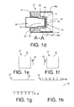
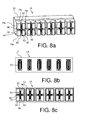
- An electrical connector assembly 10 has an in Figures 1a - 1h shown plug housing 12 and a in Figures 2a -2g illustrated Gezzansteckbauteil 14 which is partially receivable in the plug housing 12 in a plugged state of the Gezzauseinsteckbauteils 14.
- the plug housing 12 has a base body 16 which has six recesses 18, which are each formed identically. Each recess 18 of the plug housing 12 is formed in a chamber shape with a rectangular cross-section and introduced from a common top of the Grundgropers 16 in the base body 16.
- Six passage openings 20 of the body 16 of the plug housing 12 extend through the body 16, and in each case a passage opening 20 opens into a bottom wall 22 of a recess 18.
- the passage opening 20 tapers stepwise with a step towards the recess 18 and has an elongated, rectangular cross section on.
- a depth direction of the passage opening 20 corresponds to a depth direction of the recess 18.
- a portion 24 of a boundary wall 26 of the passage opening 20 extends perpendicular to the depth direction of the through hole 20 and forms a full contact surface for a formed as a contact blade male contact element 28 of the electrical connector assembly 10th
- a bow-shaped contact element 30 of the plug-in housing 12 is arranged adjacent to and in alignment with a passage opening 20 in a recess 18 and projects into the recess 18 from the bottom wall 22 from.
- the contact element 30 has a substantially U-shaped body with a first and second leg 32, 34 and a perpendicular to the first and second leg 32, 34 extending connecting portion 36.
- One leg end 38, 40 of the first and second leg 32, 34 is in each case connected to a section of the bottom wall 22 of the recess adjacent to an edge portion 42, 44 of an edge 46 of the passage opening 20.
- the abutment element 30 is arranged centrally in the recess 18 and spaced from four side walls 48a-d of the recess 18.
- the plug housing 12 and the six contact elements 30 are manufactured in one piece from plastic.
- Each contact blade 28 has a flat, one-piece body of constant thickness, which tapers step-like towards one end with a step.
- the contact blade 28 is positively received in the through hole 20 and a tapered portion 50 of the contact blade 28 is located by means of three End faces positively against an opening 20 facing the inside of the contact element 30 at.
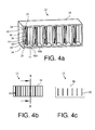
- the Gezzauseinsteckbauteil 14 has a cuboid base body 52 on which six identically shaped nose-shaped projections 54 are arranged.
- a recess 56 of six mutually substantially parallel extending and identically formed recesses 54 extending through the body 52 into an extension 54.
- a through hole 58 of six through holes 58 of the GeHouseinsteckbauteils 14 is centered in a circumferentially closed end face 60 of the extension 54, which is formed by an outer side of a bottom wall 59 of the recess 54.
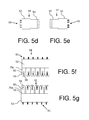
- a female contact element 61 having a contact tulip is arranged in the recess 56 in the region of the nose-shaped extension 54 adjacent to the passage opening 58.
- the contact tulip has two opposing spring arms 62, 64, each of which is formed in a threefold manner, that is, each having three elongated finger portions.
- the female contact element 61 has, in addition to the contact tulip, a flat section which is connected to the contact tulip and arranged along a longitudinal direction of the female contact element 61 so as to be spaced from the bottom wall 59 of the recess 56.
- the contact tulip and the flat portion are formed as a one-piece, folded stamped component, which has two mirror-image folding sections with respect to a center plane of the female contact element 61.
- the center plane contains the longitudinal direction of the female contact element and extends perpendicular to the plane in Figure 3c ,
- the two folding sections 61 are positively connected to one another in the region of the flat section of the female contact element 61. Ends of the two opposing spring arms 62, 64 of the contact tulip of the female contact element 61 are arranged with a small clearance of perpendicular to the depth direction of the recess 56 extending portions 66, 67 of the bottom wall 59 of the recess 56 spaced.
- An over-spring 70 is clipped over the spring arms 62, 64 of the contact tulip of the female contact element 61 and receives the spring arms 62, 64 in their fauxgeklipsten state non-positively.
- the over-spring 70 is likewise designed as a one-piece, folded stamped component which has two mirror-image folding sections, viewed with respect to its center plane.
- the middle plane is perpendicular to the plane of Figure 3c and includes a longitudinal direction of the over-spring 70, which corresponds to the longitudinal direction of the female contact element 61 and the depth direction of the recess 56 e.
- the over-spring 70 in its clip-on state, has a parallelepiped-shaped section, on which two spring arms 71, 72, each of three-part design, are fastened.
- the spring arms 62, 64 of the female contact element 61 are fingerwise covered in the clipped over the female contact element 61 state of the over-spring 70 of the spring arms 71 and 72 of the over-spring 70 and jump fingerwise slightly ahead of the spring arms 71, 72 of the over-spring 70.
- the one-piece Gekoruseinsteckbauteil 14 is made of plastic.
- each nose-shaped extension 54 of the GeHouseinsteckbauteils 14 in the corresponding recess 18 of the plug housing 12 is received and the main body 52 sits circumferentially on end portions of the boundary walls 48 a - 48 d of the recess 18.
- the end face 60 of the extension 54 is supported at a distance from the edge 46 of the passage opening 20 on the bottom wall 22 of the recess 18.
- the legs 32, 34 and the connecting portion 36 of the contact element 30 are received in the nose-shaped extension 54.
- the spring arms 62, 64 of the contact tulip of the female contact element 61 laterally engage the abutment element 30 and abutting the abutment member 30 end face of the portion 50 of the contact blade 28 and abut against opposite and carbzugbaren side surfaces 73, 74 of the portion 50 of the contact blade 28.
- an electrical connection between the contact blade 28 and the contact tulip of the female contact element 61 is accomplished, so that a first conductor arrangement 76, which is connected to the female contact elements 61 by means of a plug connection, and a second conductor arrangement 78, which by means of clamping connection with the contact blades 28th is connected, over 36 electrical contact points are electrically contacted.
- the first and second conductor arrangement 78, 80 are indicated by dashed lines.
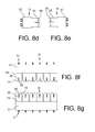
- FIGS. 4a-6c illustrated electrical connector assembly 10 according to a second embodiment is formed similar to the electrical connector assembly 10 according to the first embodiment.
- legs 32, 34 of a contact element 30 of a plug-in housing 12 seen along its longitudinal extent, are completely connected to opposite side walls 48b, 48d of the recess 18.
- the longitudinal extension of the legs 32, 34 corresponds to the depth direction of the recess 18. Mit In other words, the legs 32, 34 seen along the longitudinal direction of the contact element 30 is wider than the legs 32, 34 of the in FIGS. 1a, 1b and 1c formed contact element 30 is formed.
- a Gepatiuseinsteckbauteil 14 of the electrical connector assembly 10 has in addition to the in Fig. 2a to 3c Housing insertion member 14 shown two lateral openings 80, 82 in opposite side walls 79a, c of side walls 79a-d and an end face 60 of a nose-shaped extension 54, each having a substantially rectangular cross-section and the recess 56 and the passage opening 58 in the longitudinal direction of the passage opening 58 connect to the outside.
- the side walls 79a, c of the extension 54 are formed by opposite side walls of the recess 56, which, viewed in the longitudinal direction of the passage opening 58, delimit the recess 56.
- the end face 60 corresponds to an outer surface of a bottom wall 59 of the recess 56.
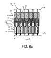
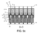
- FIGS. 7a-9c shown electrical connector assembly 10 according to a third embodiment is similar to the connector assembly according to the second embodiment formed in FIGS. 4a to 6c is shown.
- Recesses 18 of a plug-in housing 12 are in FIG. 9c shown in dashed lines.
- the plug housing 12 additionally has two web-shaped reinforcing elements 84, 86 which are arranged in the recess 18 and each extend from a side wall 48a or 48b of two opposite side walls 48a, 48c of the recess 18 to one side of a contact element 30 and are partially connected to the abutment member 30 and the corresponding side wall 48a, 48c.
- the reinforcing elements 84, 86 are arranged centrally in the recess 18 as seen along a longitudinal extent of the abutment element 30 and connected to the bottom wall 22 of the recess 18.
- the plug housing 12, the contact elements 30 and the reinforcing elements 85, 86 are integrally formed of plastic.
- a Gepatiuseinsteckbauteil 14 of the electrical connector assembly 10 additionally has in opposite side walls 79b, d and an end face 60 of each extension 54, two lateral openings 88, 90 which have a substantially rectangular cross-section and perpendicular to the passage opening 58 of the nose-shaped extension 64 extend.
- the side walls 79b, d are formed by corresponding side walls of the recess 56.
- the lateral openings 88, 90 are arranged along a longitudinal extent of the passage opening 58 in the center in the nose-shaped extension 54.
- Spring arms 62, 64 of a female contact element 61 are each formed in two parts, that is, each with two elongate finger portions.
- each spring arm 62, 64 are spaced apart on opposite sides of the side aperture 90, 88 and from the side aperture 90, 88.
- Spring arms 71, 72 of an over-spring 70 are also each formed in two parts and two finger portions of each spring arm 71, 72 of the over-spring 70 are of the corresponding lateral opening 88, 90 arranged at a distance.
- the relative arrangement of the spring arms 62, 64 of the female contact element 61 and the spring arms 71, 72 of the over-spring 70 is similar to that in FIGS. 3a-3c and 6a - 6c shown relative arrangements of the spring arms 62, 64 of the female contact element 61 and the spring arms 71, 72 of the over-spring 70th
- a first and a second conductor arrangement 76, 78 are contacted with one another via 24 contact points in an electrically conductive manner.
Landscapes
- Connector Housings Or Holding Contact Members (AREA)
Applications Claiming Priority (1)
| Application Number | Priority Date | Filing Date | Title |
|---|---|---|---|
| DE102012105839.3A DE102012105839A1 (de) | 2012-07-02 | 2012-07-02 | Steckgehäuse zum zumindest teilweisen Aufnehmen eines Gehäuseeinsteckbauteils und elektrische Steckverbindungsanordnung zum Miteinander-Verbinden eines männlichen Kontaktelements und eines weiblichen Kontaktelements |
Publications (3)
| Publication Number | Publication Date |
|---|---|
| EP2683036A1 true EP2683036A1 (fr) | 2014-01-08 |
| EP2683036B1 EP2683036B1 (fr) | 2017-04-05 |
| EP2683036B2 EP2683036B2 (fr) | 2026-01-21 |
Family
ID=48669798
Family Applications (1)
| Application Number | Title | Priority Date | Filing Date |
|---|---|---|---|
| EP13173022.8A Active EP2683036B2 (fr) | 2012-07-02 | 2013-06-20 | Boîtier de connexion destiné à loger au moins partiellement un élément connecteur de boîtier et agencement de connecteur à fiches destiné à relier entre eux un élément de contact mâle et un élément de contact femelle |
Country Status (3)
| Country | Link |
|---|---|
| EP (1) | EP2683036B2 (fr) |
| DE (2) | DE102012105839A1 (fr) |
| ES (1) | ES2625000T3 (fr) |
Cited By (2)
| Publication number | Priority date | Publication date | Assignee | Title |
|---|---|---|---|---|
| EP3591768A1 (fr) * | 2018-07-04 | 2020-01-08 | TE Connectivity Germany GmbH | Agencement de contact protégés contre tout contact |
| JP2020129461A (ja) * | 2019-02-08 | 2020-08-27 | 矢崎総業株式会社 | コネクタ |
Families Citing this family (4)
| Publication number | Priority date | Publication date | Assignee | Title |
|---|---|---|---|---|
| DE202015009490U1 (de) | 2015-05-11 | 2017-12-08 | Wago Verwaltungsgesellschaft Mbh | Berührschutzelement und elektrischer Steckverbinder |
| DE102018109557A1 (de) | 2018-04-20 | 2019-10-24 | HARTING Electronics GmbH | Berührschutz |
| DE102021108628A1 (de) | 2021-04-07 | 2022-10-13 | WAGO Verwaltungsgesellschaft mit beschränkter Haftung | Berührschutzelement und elektrischer Steckverbinder |
| DE102023207183A1 (de) | 2023-07-27 | 2025-01-30 | Robert Bosch Gesellschaft mit beschränkter Haftung | Hochstromstecker, Leistungskontakt für einen Hochstromstecker und Berührschutzbaugruppe |
Citations (2)
| Publication number | Priority date | Publication date | Assignee | Title |
|---|---|---|---|---|
| DE202008002091U1 (de) * | 2008-02-14 | 2008-04-24 | Phoenix Contact Gmbh & Co. Kg | Elektrischer Anschlußstecker |
| DE102010017262A1 (de) * | 2010-06-07 | 2011-12-08 | Phoenix Contact Gmbh & Co. Kg | Verriegelungseinrichtung und Anschlussstecker mit Verriegelungseinrichtung |
Family Cites Families (10)
| Publication number | Priority date | Publication date | Assignee | Title |
|---|---|---|---|---|
| US2992401A (en) * | 1957-11-06 | 1961-07-11 | Frank Adam Electric Co | Plug-in busduct |
| US3868162A (en) * | 1973-09-04 | 1975-02-25 | Elfab Corp | Electrical connector |
| JPH0716312Y2 (ja) * | 1989-02-28 | 1995-04-12 | ホシデン株式会社 | コネクタ |
| US5360349A (en) | 1993-03-31 | 1994-11-01 | Teradyne, Inc. | Power connector |
| DE4406879A1 (de) † | 1994-03-03 | 1995-09-07 | Bosch Gmbh Robert | Akkumulatorpaket für Elektrohandwerkzeugmaschinen |
| JPH0950851A (ja) * | 1995-08-04 | 1997-02-18 | Amp Japan Ltd | 電気コネクタ |
| NO982678L (no) | 1997-06-26 | 1998-12-28 | Siemens Ag | Pluggkoblingsstykke |
| US6629853B2 (en) | 2001-05-17 | 2003-10-07 | Tyco Electronics Corporation | Self-aligning power connector system |
| US6488549B1 (en) | 2001-06-06 | 2002-12-03 | Tyco Electronics Corporation | Electrical connector assembly with separate arcing zones |
| US7955097B2 (en) * | 2009-10-30 | 2011-06-07 | O'leary Timothy | Plug-in outlet (PIO) with floating fingerguard |
-
2012
- 2012-07-02 DE DE102012105839.3A patent/DE102012105839A1/de not_active Ceased
-
2013
- 2013-06-20 ES ES13173022.8T patent/ES2625000T3/es active Active
- 2013-06-20 DE DE202013012806.2U patent/DE202013012806U1/de not_active Expired - Lifetime
- 2013-06-20 EP EP13173022.8A patent/EP2683036B2/fr active Active
Patent Citations (2)
| Publication number | Priority date | Publication date | Assignee | Title |
|---|---|---|---|---|
| DE202008002091U1 (de) * | 2008-02-14 | 2008-04-24 | Phoenix Contact Gmbh & Co. Kg | Elektrischer Anschlußstecker |
| DE102010017262A1 (de) * | 2010-06-07 | 2011-12-08 | Phoenix Contact Gmbh & Co. Kg | Verriegelungseinrichtung und Anschlussstecker mit Verriegelungseinrichtung |
Cited By (5)
| Publication number | Priority date | Publication date | Assignee | Title |
|---|---|---|---|---|
| EP3591768A1 (fr) * | 2018-07-04 | 2020-01-08 | TE Connectivity Germany GmbH | Agencement de contact protégés contre tout contact |
| KR20200004761A (ko) * | 2018-07-04 | 2020-01-14 | 티이 커넥티버티 저머니 게엠베하 | 접촉 방지 접점 배열체 |
| JP2020017522A (ja) * | 2018-07-04 | 2020-01-30 | ティーイー コネクティビティ ジャーマニー ゲゼルシャフト ミット ベシュレンクテル ハフツンクTE Connectivity Germany GmbH | 接触防止コンタクト構成 |
| US10855018B2 (en) | 2018-07-04 | 2020-12-01 | Te Connectivity Germany Gmbh | Touch-proof contact arrangement |
| JP2020129461A (ja) * | 2019-02-08 | 2020-08-27 | 矢崎総業株式会社 | コネクタ |
Also Published As
| Publication number | Publication date |
|---|---|
| ES2625000T3 (es) | 2017-07-18 |
| DE102012105839A1 (de) | 2014-02-20 |
| DE202013012806U1 (de) | 2019-11-24 |
| EP2683036B2 (fr) | 2026-01-21 |
| EP2683036B1 (fr) | 2017-04-05 |
Similar Documents
| Publication | Publication Date | Title |
|---|---|---|
| DE102013110082C5 (de) | Steckverbinder | |
| DE102014202414B4 (de) | Elektrische Steckverbindungsvorrichtung mit Federverbindungselement und mit kompakter Betätigungsvorrichtung, und mehrpoliger Steckverbinder mit mehreren derartigen Federkontakten | |
| DE10226279C1 (de) | Hermaphroditisches Kontaktteil | |
| EP2683036B1 (fr) | Boîtier de connexion destiné à loger au moins partiellement un élément connecteur de boîtier et agencement de connecteur à fiches destiné à relier entre eux un élément de contact mâle et un élément de contact femelle | |
| EP0734094B1 (fr) | Elément de contact électrique | |
| EP3375048B1 (fr) | Contact à enficher | |
| EP3446366A1 (fr) | Contact enfichable | |
| DE20114612U1 (de) | Reihenklemme mit Schneidkontakten und Anschlußvorrichtung | |
| EP2026417B1 (fr) | Connecteur électrique doté d'éléments de contact hermaphrodites | |
| DE19960627A1 (de) | Elektrischer Anschlußkontakt und Lampenfassung mit einem solchen Kontakt | |
| DE2940226C2 (fr) | ||
| DE102013106117B4 (de) | Steckverbinderanordnung und Steckverbindungssystem | |
| DE102019117669B4 (de) | Verbinder und Verbinderanordnung | |
| EP3292591A1 (fr) | Borne de connexion de conducteur | |
| DE19949387B4 (de) | Kontaktteil für Anschlussklemme | |
| EP3000153A1 (fr) | Cavalier enfichable comprenant des éléments en tôle superposés | |
| DE60222034T2 (de) | Elektrische Steckverbinderanordnung | |
| EP0865105B1 (fr) | Douille de connexion électrique avec ressort de contact et douille utilisable comme contact terminal | |
| DE3525297A1 (de) | Elektrische steckverbindung | |
| EP2169775B1 (fr) | Contact symétrique électrique | |
| DE19945412B4 (de) | Elektrischer Kontakt und elektrischer Steckverbinder mit einem solchen Kontakt | |
| DE102007039307B4 (de) | Steckverbinder | |
| EP3235069A1 (fr) | Connecteur hermaphrodite | |
| DE102014114352B3 (de) | Stiftleiste | |
| DE19809881C2 (de) | Elektrischer Steckverbinder |
Legal Events
| Date | Code | Title | Description |
|---|---|---|---|
| PUAI | Public reference made under article 153(3) epc to a published international application that has entered the european phase |
Free format text: ORIGINAL CODE: 0009012 |
|
| AK | Designated contracting states |
Kind code of ref document: A1 Designated state(s): AL AT BE BG CH CY CZ DE DK EE ES FI FR GB GR HR HU IE IS IT LI LT LU LV MC MK MT NL NO PL PT RO RS SE SI SK SM TR |
|
| AX | Request for extension of the european patent |
Extension state: BA ME |
|
| 17P | Request for examination filed |
Effective date: 20140331 |
|
| RBV | Designated contracting states (corrected) |
Designated state(s): AL AT BE BG CH CY CZ DE DK EE ES FI FR GB GR HR HU IE IS IT LI LT LU LV MC MK MT NL NO PL PT RO RS SE SI SK SM TR |
|
| GRAP | Despatch of communication of intention to grant a patent |
Free format text: ORIGINAL CODE: EPIDOSNIGR1 |
|
| INTG | Intention to grant announced |
Effective date: 20161021 |
|
| STAA | Information on the status of an ep patent application or granted ep patent |
Free format text: STATUS: GRANT OF PATENT IS INTENDED |
|
| GRAS | Grant fee paid |
Free format text: ORIGINAL CODE: EPIDOSNIGR3 |
|
| GRAA | (expected) grant |
Free format text: ORIGINAL CODE: 0009210 |
|
| STAA | Information on the status of an ep patent application or granted ep patent |
Free format text: STATUS: THE PATENT HAS BEEN GRANTED |
|
| AK | Designated contracting states |
Kind code of ref document: B1 Designated state(s): AL AT BE BG CH CY CZ DE DK EE ES FI FR GB GR HR HU IE IS IT LI LT LU LV MC MK MT NL NO PL PT RO RS SE SI SK SM TR |
|
| REG | Reference to a national code |
Ref country code: GB Ref legal event code: FG4D Free format text: NOT ENGLISH |
|
| REG | Reference to a national code |
Ref country code: CH Ref legal event code: EP |
|
| REG | Reference to a national code |
Ref country code: AT Ref legal event code: REF Ref document number: 882617 Country of ref document: AT Kind code of ref document: T Effective date: 20170415 |
|
| REG | Reference to a national code |
Ref country code: IE Ref legal event code: FG4D Free format text: LANGUAGE OF EP DOCUMENT: GERMAN |
|
| REG | Reference to a national code |
Ref country code: DE Ref legal event code: R096 Ref document number: 502013006855 Country of ref document: DE |
|
| REG | Reference to a national code |
Ref country code: DK Ref legal event code: T3 Effective date: 20170522 |
|
| REG | Reference to a national code |
Ref country code: NL Ref legal event code: FP |
|
| REG | Reference to a national code |
Ref country code: FR Ref legal event code: PLFP Year of fee payment: 5 |
|
| REG | Reference to a national code |
Ref country code: ES Ref legal event code: FG2A Ref document number: 2625000 Country of ref document: ES Kind code of ref document: T3 Effective date: 20170718 |
|
| REG | Reference to a national code |
Ref country code: LT Ref legal event code: MG4D |
|
| PG25 | Lapsed in a contracting state [announced via postgrant information from national office to epo] |
Ref country code: HR Free format text: LAPSE BECAUSE OF FAILURE TO SUBMIT A TRANSLATION OF THE DESCRIPTION OR TO PAY THE FEE WITHIN THE PRESCRIBED TIME-LIMIT Effective date: 20170405 Ref country code: NO Free format text: LAPSE BECAUSE OF FAILURE TO SUBMIT A TRANSLATION OF THE DESCRIPTION OR TO PAY THE FEE WITHIN THE PRESCRIBED TIME-LIMIT Effective date: 20170705 Ref country code: FI Free format text: LAPSE BECAUSE OF FAILURE TO SUBMIT A TRANSLATION OF THE DESCRIPTION OR TO PAY THE FEE WITHIN THE PRESCRIBED TIME-LIMIT Effective date: 20170405 Ref country code: GR Free format text: LAPSE BECAUSE OF FAILURE TO SUBMIT A TRANSLATION OF THE DESCRIPTION OR TO PAY THE FEE WITHIN THE PRESCRIBED TIME-LIMIT Effective date: 20170706 Ref country code: LT Free format text: LAPSE BECAUSE OF FAILURE TO SUBMIT A TRANSLATION OF THE DESCRIPTION OR TO PAY THE FEE WITHIN THE PRESCRIBED TIME-LIMIT Effective date: 20170405 |
|
| PG25 | Lapsed in a contracting state [announced via postgrant information from national office to epo] |
Ref country code: SE Free format text: LAPSE BECAUSE OF FAILURE TO SUBMIT A TRANSLATION OF THE DESCRIPTION OR TO PAY THE FEE WITHIN THE PRESCRIBED TIME-LIMIT Effective date: 20170405 Ref country code: PL Free format text: LAPSE BECAUSE OF FAILURE TO SUBMIT A TRANSLATION OF THE DESCRIPTION OR TO PAY THE FEE WITHIN THE PRESCRIBED TIME-LIMIT Effective date: 20170405 Ref country code: BG Free format text: LAPSE BECAUSE OF FAILURE TO SUBMIT A TRANSLATION OF THE DESCRIPTION OR TO PAY THE FEE WITHIN THE PRESCRIBED TIME-LIMIT Effective date: 20170705 Ref country code: LV Free format text: LAPSE BECAUSE OF FAILURE TO SUBMIT A TRANSLATION OF THE DESCRIPTION OR TO PAY THE FEE WITHIN THE PRESCRIBED TIME-LIMIT Effective date: 20170405 Ref country code: IS Free format text: LAPSE BECAUSE OF FAILURE TO SUBMIT A TRANSLATION OF THE DESCRIPTION OR TO PAY THE FEE WITHIN THE PRESCRIBED TIME-LIMIT Effective date: 20170805 Ref country code: RS Free format text: LAPSE BECAUSE OF FAILURE TO SUBMIT A TRANSLATION OF THE DESCRIPTION OR TO PAY THE FEE WITHIN THE PRESCRIBED TIME-LIMIT Effective date: 20170405 |
|
| REG | Reference to a national code |
Ref country code: DE Ref legal event code: R026 Ref document number: 502013006855 Country of ref document: DE |
|
| PLBI | Opposition filed |
Free format text: ORIGINAL CODE: 0009260 |
|
| PLAX | Notice of opposition and request to file observation + time limit sent |
Free format text: ORIGINAL CODE: EPIDOSNOBS2 |
|
| PG25 | Lapsed in a contracting state [announced via postgrant information from national office to epo] |
Ref country code: RO Free format text: LAPSE BECAUSE OF FAILURE TO SUBMIT A TRANSLATION OF THE DESCRIPTION OR TO PAY THE FEE WITHIN THE PRESCRIBED TIME-LIMIT Effective date: 20170405 Ref country code: EE Free format text: LAPSE BECAUSE OF FAILURE TO SUBMIT A TRANSLATION OF THE DESCRIPTION OR TO PAY THE FEE WITHIN THE PRESCRIBED TIME-LIMIT Effective date: 20170405 Ref country code: CZ Free format text: LAPSE BECAUSE OF FAILURE TO SUBMIT A TRANSLATION OF THE DESCRIPTION OR TO PAY THE FEE WITHIN THE PRESCRIBED TIME-LIMIT Effective date: 20170405 Ref country code: SK Free format text: LAPSE BECAUSE OF FAILURE TO SUBMIT A TRANSLATION OF THE DESCRIPTION OR TO PAY THE FEE WITHIN THE PRESCRIBED TIME-LIMIT Effective date: 20170405 Ref country code: MC Free format text: LAPSE BECAUSE OF FAILURE TO SUBMIT A TRANSLATION OF THE DESCRIPTION OR TO PAY THE FEE WITHIN THE PRESCRIBED TIME-LIMIT Effective date: 20170405 |
|
| REG | Reference to a national code |
Ref country code: CH Ref legal event code: PL |
|
| 26 | Opposition filed |
Opponent name: WAGO KONTAKTTECHNIK GMBH & CO. KG Effective date: 20180103 |
|
| PG25 | Lapsed in a contracting state [announced via postgrant information from national office to epo] |
Ref country code: SM Free format text: LAPSE BECAUSE OF FAILURE TO SUBMIT A TRANSLATION OF THE DESCRIPTION OR TO PAY THE FEE WITHIN THE PRESCRIBED TIME-LIMIT Effective date: 20170405 |
|
| REG | Reference to a national code |
Ref country code: IE Ref legal event code: MM4A |
|
| GBPC | Gb: european patent ceased through non-payment of renewal fee |
Effective date: 20170705 |
|
| PG25 | Lapsed in a contracting state [announced via postgrant information from national office to epo] |
Ref country code: LI Free format text: LAPSE BECAUSE OF NON-PAYMENT OF DUE FEES Effective date: 20170630 Ref country code: CH Free format text: LAPSE BECAUSE OF NON-PAYMENT OF DUE FEES Effective date: 20170630 Ref country code: GB Free format text: LAPSE BECAUSE OF NON-PAYMENT OF DUE FEES Effective date: 20170705 Ref country code: IE Free format text: LAPSE BECAUSE OF NON-PAYMENT OF DUE FEES Effective date: 20170620 Ref country code: LU Free format text: LAPSE BECAUSE OF NON-PAYMENT OF DUE FEES Effective date: 20170620 |
|
| PLBB | Reply of patent proprietor to notice(s) of opposition received |
Free format text: ORIGINAL CODE: EPIDOSNOBS3 |
|
| PG25 | Lapsed in a contracting state [announced via postgrant information from national office to epo] |
Ref country code: SI Free format text: LAPSE BECAUSE OF FAILURE TO SUBMIT A TRANSLATION OF THE DESCRIPTION OR TO PAY THE FEE WITHIN THE PRESCRIBED TIME-LIMIT Effective date: 20170405 |
|
| REG | Reference to a national code |
Ref country code: BE Ref legal event code: MM Effective date: 20170630 |
|
| REG | Reference to a national code |
Ref country code: FR Ref legal event code: PLFP Year of fee payment: 6 |
|
| PG25 | Lapsed in a contracting state [announced via postgrant information from national office to epo] |
Ref country code: BE Free format text: LAPSE BECAUSE OF NON-PAYMENT OF DUE FEES Effective date: 20170630 |
|
| PG25 | Lapsed in a contracting state [announced via postgrant information from national office to epo] |
Ref country code: MT Free format text: LAPSE BECAUSE OF FAILURE TO SUBMIT A TRANSLATION OF THE DESCRIPTION OR TO PAY THE FEE WITHIN THE PRESCRIBED TIME-LIMIT Effective date: 20170405 |
|
| PG25 | Lapsed in a contracting state [announced via postgrant information from national office to epo] |
Ref country code: HU Free format text: LAPSE BECAUSE OF FAILURE TO SUBMIT A TRANSLATION OF THE DESCRIPTION OR TO PAY THE FEE WITHIN THE PRESCRIBED TIME-LIMIT; INVALID AB INITIO Effective date: 20130620 |
|
| PGFP | Annual fee paid to national office [announced via postgrant information from national office to epo] |
Ref country code: NL Payment date: 20190626 Year of fee payment: 7 |
|
| PG25 | Lapsed in a contracting state [announced via postgrant information from national office to epo] |
Ref country code: CY Free format text: LAPSE BECAUSE OF NON-PAYMENT OF DUE FEES Effective date: 20170405 |
|
| PGFP | Annual fee paid to national office [announced via postgrant information from national office to epo] |
Ref country code: AT Payment date: 20190621 Year of fee payment: 7 Ref country code: ES Payment date: 20190725 Year of fee payment: 7 |
|
| PG25 | Lapsed in a contracting state [announced via postgrant information from national office to epo] |
Ref country code: MK Free format text: LAPSE BECAUSE OF FAILURE TO SUBMIT A TRANSLATION OF THE DESCRIPTION OR TO PAY THE FEE WITHIN THE PRESCRIBED TIME-LIMIT Effective date: 20170405 |
|
| PG25 | Lapsed in a contracting state [announced via postgrant information from national office to epo] |
Ref country code: TR Free format text: LAPSE BECAUSE OF FAILURE TO SUBMIT A TRANSLATION OF THE DESCRIPTION OR TO PAY THE FEE WITHIN THE PRESCRIBED TIME-LIMIT Effective date: 20170405 |
|
| APBM | Appeal reference recorded |
Free format text: ORIGINAL CODE: EPIDOSNREFNO |
|
| APBP | Date of receipt of notice of appeal recorded |
Free format text: ORIGINAL CODE: EPIDOSNNOA2O |
|
| APAH | Appeal reference modified |
Free format text: ORIGINAL CODE: EPIDOSCREFNO |
|
| APBQ | Date of receipt of statement of grounds of appeal recorded |
Free format text: ORIGINAL CODE: EPIDOSNNOA3O |
|
| PG25 | Lapsed in a contracting state [announced via postgrant information from national office to epo] |
Ref country code: PT Free format text: LAPSE BECAUSE OF FAILURE TO SUBMIT A TRANSLATION OF THE DESCRIPTION OR TO PAY THE FEE WITHIN THE PRESCRIBED TIME-LIMIT Effective date: 20170405 |
|
| PG25 | Lapsed in a contracting state [announced via postgrant information from national office to epo] |
Ref country code: AL Free format text: LAPSE BECAUSE OF FAILURE TO SUBMIT A TRANSLATION OF THE DESCRIPTION OR TO PAY THE FEE WITHIN THE PRESCRIBED TIME-LIMIT Effective date: 20170405 |
|
| REG | Reference to a national code |
Ref country code: NL Ref legal event code: MM Effective date: 20200701 |
|
| REG | Reference to a national code |
Ref country code: AT Ref legal event code: MM01 Ref document number: 882617 Country of ref document: AT Kind code of ref document: T Effective date: 20200620 |
|
| PG25 | Lapsed in a contracting state [announced via postgrant information from national office to epo] |
Ref country code: NL Free format text: LAPSE BECAUSE OF NON-PAYMENT OF DUE FEES Effective date: 20200701 |
|
| PG25 | Lapsed in a contracting state [announced via postgrant information from national office to epo] |
Ref country code: AT Free format text: LAPSE BECAUSE OF NON-PAYMENT OF DUE FEES Effective date: 20200620 |
|
| REG | Reference to a national code |
Ref country code: ES Ref legal event code: FD2A Effective date: 20211103 |
|
| PG25 | Lapsed in a contracting state [announced via postgrant information from national office to epo] |
Ref country code: ES Free format text: LAPSE BECAUSE OF NON-PAYMENT OF DUE FEES Effective date: 20200621 |
|
| PLAB | Opposition data, opponent's data or that of the opponent's representative modified |
Free format text: ORIGINAL CODE: 0009299OPPO |
|
| R26 | Opposition filed (corrected) |
Opponent name: WAGO GMBH & CO. KG Effective date: 20180103 |
|
| PLAB | Opposition data, opponent's data or that of the opponent's representative modified |
Free format text: ORIGINAL CODE: 0009299OPPO |
|
| P01 | Opt-out of the competence of the unified patent court (upc) registered |
Effective date: 20230424 |
|
| R26 | Opposition filed (corrected) |
Opponent name: WAGO GMBH & CO. KG Effective date: 20180103 |
|
| APBU | Appeal procedure closed |
Free format text: ORIGINAL CODE: EPIDOSNNOA9O |
|
| PLAY | Examination report in opposition despatched + time limit |
Free format text: ORIGINAL CODE: EPIDOSNORE2 |
|
| PLBC | Reply to examination report in opposition received |
Free format text: ORIGINAL CODE: EPIDOSNORE3 |
|
| PGFP | Annual fee paid to national office [announced via postgrant information from national office to epo] |
Ref country code: DK Payment date: 20250619 Year of fee payment: 13 |
|
| PGFP | Annual fee paid to national office [announced via postgrant information from national office to epo] |
Ref country code: FR Payment date: 20250624 Year of fee payment: 13 |
|
| PGFP | Annual fee paid to national office [announced via postgrant information from national office to epo] |
Ref country code: DE Payment date: 20250827 Year of fee payment: 13 |
|
| PGFP | Annual fee paid to national office [announced via postgrant information from national office to epo] |
Ref country code: IT Payment date: 20250623 Year of fee payment: 13 |
|
| PUAH | Patent maintained in amended form |
Free format text: ORIGINAL CODE: 0009272 |
|
| STAA | Information on the status of an ep patent application or granted ep patent |
Free format text: STATUS: PATENT MAINTAINED AS AMENDED |
|
| REG | Reference to a national code |
Ref country code: CH Ref legal event code: M12 Free format text: ST27 STATUS EVENT CODE: U-0-0-M10-M12 (AS PROVIDED BY THE NATIONAL OFFICE) Effective date: 20251224 |
|
| 27A | Patent maintained in amended form |
Effective date: 20260121 |
|
| AK | Designated contracting states |
Kind code of ref document: B2 Designated state(s): AL AT BE BG CH CY CZ DE DK EE ES FI FR GB GR HR HU IE IS IT LI LT LU LV MC MK MT NL NO PL PT RO RS SE SI SK SM TR |
|
| REG | Reference to a national code |
Ref country code: DE Ref legal event code: R102 Ref document number: 502013006855 Country of ref document: DE |