EP2683041B1 - Verfahren zur herstellung einer zündkerze - Google Patents
Verfahren zur herstellung einer zündkerze Download PDFInfo
- Publication number
- EP2683041B1 EP2683041B1 EP12754851.9A EP12754851A EP2683041B1 EP 2683041 B1 EP2683041 B1 EP 2683041B1 EP 12754851 A EP12754851 A EP 12754851A EP 2683041 B1 EP2683041 B1 EP 2683041B1
- Authority
- EP
- European Patent Office
- Prior art keywords
- insulator
- metallic shell
- spark plug
- defect
- center electrode
- Prior art date
- Legal status (The legal status is an assumption and is not a legal conclusion. Google has not performed a legal analysis and makes no representation as to the accuracy of the status listed.)
- Active
Links
Images


Classifications
-
- H—ELECTRICITY
- H01—ELECTRIC ELEMENTS
- H01T—SPARK GAPS; OVERVOLTAGE ARRESTERS USING SPARK GAPS; SPARKING PLUGS; CORONA DEVICES; GENERATING IONS TO BE INTRODUCED INTO NON-ENCLOSED GASES
- H01T21/00—Apparatus or processes specially adapted for the manufacture or maintenance of spark gaps or sparking plugs
- H01T21/02—Apparatus or processes specially adapted for the manufacture or maintenance of spark gaps or sparking plugs of sparking plugs
-
- H—ELECTRICITY
- H01—ELECTRIC ELEMENTS
- H01T—SPARK GAPS; OVERVOLTAGE ARRESTERS USING SPARK GAPS; SPARKING PLUGS; CORONA DEVICES; GENERATING IONS TO BE INTRODUCED INTO NON-ENCLOSED GASES
- H01T13/00—Sparking plugs
- H01T13/58—Testing
- H01T13/60—Testing of electrical properties
Definitions
- the present invention relates to a method of manufacturing a spark plug for providing ignition in an internal combustion engine, and more particularly to a method of manufacturing a spark plug equipped with an insulator having dielectric strength.
- a spark plug for providing ignition in an internal combustion engine such as an automobile engine, generally includes a tubular metallic shell; a tubular insulator disposed in the bore of the metallic shell; a center electrode disposed in a forward end portion of the axial bore of the insulator; a metal terminal disposed in a rear portion of the axial bore; and a ground electrode whose one end is joined to the forward end of the metallic shell and whose other end faces the center electrode, thereby forming a spark discharge gap therebetween.
- spark discharge is generated between the center electrode and the ground electrode and ignites fuel contained in a combustion chamber.
- the insulator has a defect, such as a fine pore, current may leak, through the defect, between the center electrode and the metallic shell (hereinafter, the current leakage may be referred to as penetrating discharge), potentially resulting in a failure to perform normal spark discharge.
- a defect such as a fine pore
- Patent Document 1 describes "a defect detection method for a ceramic insulator, characterized in that: while the ceramic insulator having a hollow portion whose one end is open is held, spark discharge is generated between a first electrode inserted into the hollow portion of the ceramic insulator and a second electrode provided in the vicinity of ceramic insulator; a check is made to see whether spark discharge generated through generation of a voltage difference between the first and second electrodes has passed through the opening of the hollow portion of the ceramic insulator; and whether or not the ceramic insulator is acceptable is judged from whether or not the spark discharge has passed through the opening of the hollow portion" (claim 5).
- the ceramic insulator is judged free of defect.
- the ceramic insulator is judged defective, since penetrating discharge has been generated through passage through a defect in the ceramic insulator.
- Patent Document 2 describes "a defect detection method for a ceramic insulator, characterized in that: ... while the interior of the pressure vessel is sealed with air having a pressure higher than the atmospheric pressure, an electric potential difference is generated between the first electrode and the second electrode to thereby detect a leak current which flows between the first electrode and the second electrode, and whether or not the ceramic insulator has a defect is judged from whether or not the leak current is greater than a predetermined value" (claim 1).
- a predetermined value a predetermined value
- US 2004/0051537 A1 describes a method of inspecting insulators to detect defects.
- US 2009/0224767 A1 describes a test method and apparatus for spark plug ceramic insulator.
- EP 0 933 847 A1 describes a spark plug for internal combustion engine and method for manufacturing the same.
- US 6 236 213 B1 describes a method and apparatus for inspecting spark plug while spark plug is installed in engine.
- EP 2 006 699 A2 describes a test method and apparatus for spark plug insulator.
- a defect detection test is conducted on the insulator in a state before attachment of the insulator to the metallic shell, etc.; accordingly, even though no defect is detected in the insulator, in the case where a defect arises in the insulator for a certain reason in the subsequent course of execution of various steps until completion of the spark plug, such as steps of attachment of the center electrode, the metallic shell, the insulator, etc., the defect which has arisen in the steps cannot be detected.
- the intermediate product is disposed within a pressure vessel, and the inner pressure of the pressure vessel is increased above the atmospheric pressure to thereby restrain the generation of the flashover; however, in order to restrain the generation of the flashover upon application of a highest voltage which is potentially applied to the spark plug in use with an internal combustion engine, the atmosphere in the pressure vessel must have a considerably high pressure. Accordingly, increasing the size of a pressurizing apparatus and complication of apparatus management are unavoidable.
- An object of the present invention is to provide a spark plug manufacturing method capable of providing a spark plug equipped with an insulator having dielectric strength, by means of judging whether or not the insulator has a defect.
- Means for solving the aforementioned problem is (1) a spark plug manufacturing method for manufacturing a spark plug comprising an insulator having an axial bore extending in a direction of an axis; a center electrode inserted into the axial bore; a metallic shell disposed externally of an outer circumference of the insulator and having a ledge projecting into interior thereof; a ground electrode joined to a forward end portion of the metallic shell and forming a gap in cooperation with the center electrode; and a packing disposed between the insulator and a surface of the ledge located on a rear side thereof opposite a forward side of the metallic shell where the gap is formed; the method being characterized by comprising a defect judgment step of judging whether or not the insulator has a defect, by means of generation of an electric potential difference between the center electrode and the metallic shell under conditions such that an assembly of the center electrode, the metallic shell, and the insulator is disposed within a pressure vessel, a high-pressure atmosphere higher in pressure than the atmospheric pressure is established within the pressure vessel, a space
- Preferred modes of the method mentioned above in (1) are as follows: (2) the space which allows the presence of insulating oil is a second space surrounded by the packing, the metallic shell, the insulator, and an imaginary plane being orthogonal to the axis and containing a forward end of the ledge; (3) the insulating oil has a relative dielectric constant of 5 or less; (4) the atmosphere within the pressure vessel has a pressure of less than 5 MPa; and (5) the defect judgment step is performed before a step of forming the gap by bending the ground electrode.
- the defect judgment step is performed by use of an assembly of at least the center electrode, the metallic shell, and the insulator; therefore, the method can detect not only a defect which arises in the insulator in the course of manufacture of the insulator, but also a defect which may arise in the insulator for various causes in manufacturing steps, such as attaching steps.
- the assembly is placed within the pressure vessel in which a high-pressure atmosphere higher in pressure than the atmospheric pressure is maintained, and whether or not a defect is present in the insulator is judged by means of generation of an electric potential difference between the center electrode and the metallic shell in a state of presence of insulating oil in the space; therefore, there can be restrained creeping discharge, which is a flashover, from the center electrode toward the packing along the surface of the insulator.
- the manufacturing method of the present invention can provide a spark plug equipped with a defect-free insulator.
- the spark plug manufacturing method of the present invention since a space which allows the presence of the insulating oil is limited to a narrow space; namely, the second space, there can be prevented a false judgment that the defect-free insulator is judged defective, which could otherwise result from bubbles which are generated in the insulating oil when an electric potential difference is generated between the center electrode and the metallic shell.
- the insulating oil has a relative dielectric constant of 5 or less, voltage to be applied to the insulator in the defect judgment step can be reduced, whereby load imposed on the insulator can be reduced.
- the spark plug manufacturing method of the present invention since the atmosphere within the pressure vessel has a pressure of less than 5 MPa, an increase in the size of a pressurizing apparatus and complication of apparatus management can be restrained.
- the defect judgment step is performed before a step of forming the gap by bending the ground electrode, the generation of spark discharge between the center electrode and the ground electrode during the defect judgment step can be further restrained.
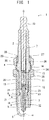
- a spark plug 1 to be manufactured by the spark plug manufacturing method of the present invention includes an insulator 2 having an axial bore 7 extending in the direction of an axis O; a center electrode 3 inserted into the axial bore 7; a metallic shell 4 disposed externally of the outer circumference of the insulator 2 and having a ledge 8 projecting into the interior thereof; a ground electrode 5 joined to a forward end portion of the metallic shell 4 and forming a gap g in cooperation with the center electrode 3; and a packing 6 disposed, with a side of the metallic shell 4 toward the gap g being taken as the forward side of the metallic shell 4, between the insulator 2 and a first surface 9 of the ledge 8 located on a side toward the rear end of the ledge 8.
- the insulator 2 is formed from a material having mechanical strength, thermal strength, electrical strength, etc.; for example, a ceramic sintered body which predominantly contains alumina, and has the axial bore 7 having a substantially cylindrical shape and extending in the direction of the axis O.
- the center electrode 3 in the form of a substantially circular column is held in a one end portion of the axial bore 7, and a metal terminal 10 in the form of a substantially circular column is held in the other end portion of the axial bore 7.
- a resistor 11 is provided as needed in the axial bore 7 between the center electrode 3 and the metal terminal 10 for the purpose of restraining the generation of radio noise, and electrically conductive glass seal layers 12 and 13 are provided on respective opposite sides of the resistor 11, thereby electrically connecting the center electrode 3 and the metal terminal 10 to each other.
- the insulator 2 has a flange portion 14 projecting radially outward and formed at a substantially central portion thereof with respect to the direction of the axis O; an intermediate trunk portion 15 located forward of the flange portion 14 and having a diameter smaller than that of the flange portion 14; and a leg portion 16 located forward of the intermediate trunk portion 15, having a diameter smaller than that of the intermediate trunk portion 15, and extending such that the diameter gradually reduces forward.
- An outer circumferential surface 17 of the intermediate trunk portion 15 and an outer circumferential surface 18 of the leg portion 16 is connected by a tapered step surface 19, and the packing 6 is disposed between the step portion 19 and the first surface 9 of the ledge 8 of the metallic shell 4 (which will be described later), the first surface 9 being located on the rear side of the ledge 8, whereby the insulator 2 is held by the metallic shell 4.
- the center electrode 3 is formed from a material having thermal conductivity, mechanical strength, etc.; for example, an Ni-based alloy, such as INCONEL (trade name) 600.
- the center electrode 3 has a head portion 21 supported by a tapered step 20 which is formed in the axial bore 7 of the insulator 2 and connects the inner circumferential surface of the intermediate trunk portion 15 and the inner circumferential surface of the leg portion 16 smaller in inside diameter than the intermediate trunk portion 15, and a trunk portion 22 extending forward from the head portion 21 and having an outside diameter smaller than that of the head portion 21, and the center electrode 3 is held in and electrically insulated from the metallic shell 4 in a state in which a forward end of the trunk portion 22 projects from the forward end surface of the insulator 2.
- the metallic shell 4 is formed from an electrically conductive steel material, such as low-carbon steel; has a substantially cylindrical shape; and accommodates and holds the insulator 2.
- the metallic shell 4 has a threaded portion 23 formed on the outer circumferential surface of its forward portion, and, by use of the threaded portion 23, the spark plug is mounted to an unillustrated cylinder head of an internal combustion engine.
- the metallic shell 4 has a flange-like gas seal portion 24 located rearward of the threaded portion 23, and a gasket 25 sandwiched between the gas seal portion 24 and the threaded portion 23.
- the metallic shell 4 has a tool engagement portion 26 located rearward of the gas seal portion 24 and allows a tool, such as a spanner or a wrench, to be engaged therewith, and a crimp portion 27 located rearward of the tool engagement portion 26.
- Ring packings 28 and talc 29 are disposed in an annular space formed between the outer circumferential surface of the insulator 2 and the inner circumferential surfaces of the crimp portion 27 and the tool engagement portion 26, whereby the insulator 2 is fixed to the metallic shell 4.
- the metallic shell 4 has an intermediate tube portion 30 located forward of the gas seal portion 24 and surrounding the intermediate trunk portion 15 of the insulator 2; the ledge 8 located forward of the intermediate tube portion 30 and projecting radially inward; and a forward tube portion 31 located forward of the ledge 8 and surrounding the leg portion 16 of the insulator 2.
- the ledge 8 has a cylindrical ledge inner circumferential surface 32 which projects most radially inward and is shortest in distance to the inner circumferential surface 18 of the leg portion 16 of the insulator 2; the tapered first surface 9 (a surface of the ledge 8 located on the side toward the rear end of the ledge 8) which connects the rear end of the ledge inner circumferential surface 32 and an intermediate-trunk-portion inner circumferential surface 33 greater in inside diameter than the ledge inner circumferential surface 32; and a tapered second surface 35 which connects the forward end of the ledge inner circumferential surface 32 and a forward-tube-portion inner circumferential surface 34 greater in inside diameter than the ledge inner circumferential surface 32.
- the ground electrode 5 is formed into, for example, a substantially rectangular columnar body, and the shape and structure of the ground electrode 5 are designed as follows: one end of the ground electrode 5 is joined to the forward end surface of the metallic shell 4, and the body of the ground electrode 5 is bent at an intermediate position so as to assume a shape resembling the letter L and such that a distal end portion of the ground electrode 5 faces a forward end portion of the center electrode 3 via the gap g.
- the ground electrode 5 is formed from a material similar to that used to form the center electrode 3.
- the defect judgment step in the spark plug manufacturing method of the present invention judges whether or not the insulator 2 has a defect, by means of generation of an electric potential difference between the center electrode 3 and the metallic shell 4 under conditions such that an assembly of the center electrode 3, the metallic shell 4, and the insulator 2 is disposed within a pressure vessel, a high-pressure atmosphere higher in pressure than the atmospheric pressure is established within the pressure vessel, a space which allows the presence of insulating oil is a first space a surrounded by the packing 6, the metallic shell 4, the insulator 2, and an imaginary plane h containing the forward end surface of the metallic shell 4, and the insulating oil is present at least in a region of the first space a where the distance between the ledge 8 and the insulator 2 becomes shortest.
- the spark plug manufacturing method of the present invention can reliably judge whether or not the insulator 2 has a defect which generates penetrating discharge.
- the highest voltage which is potentially applied is the sum of voltage to be applied to the spark plug in use with the internal combustion engine and voltage which may be accidentally applied to the spark plug (hereinafter, the sum of voltages may be referred to as required withstand voltage).
- the insulator 2 which does not generate penetrating discharge upon application of the required withstand voltage can be considered to have dielectric strength.
- the spark plug manufacturing method of the present invention can provide a spark plug equipped with the insulator 2 free from a defect which potentially causes the generation of penetrating discharge upon application of the required withstand voltage; i.e., a spark plug equipped with the insulator 2 having dielectric strength.
- an assembly of at least the center electrode 3, the metallic shell 4, and the insulator 2 is disposed within the pressure vessel.
- What is disposed within the pressure vessel may be an intermediate product which is to become a completed spark plug after the defect judgment step, or an intermediate product which is to be yielded as a result of the assembly undergoing each of the steps to be described later.
- the defect judgment step is performed on the mere insulator 2, even though no defect is detected in the insulator 2, in the case where a defect arises in the insulator 2 for a certain reason in the subsequent course of execution of various steps until completion of the spark plug, such as steps of attachment of the center electrode 3, the metallic shell 4, the insulator 2, etc., the defect which has arisen in the steps cannot be detected.
- the defect judgment step being performed on an intermediate product which is yielded at least after a step of yielding the above-mentioned assembly, desirably, on an intermediate product as close as possible to a completed product, a defect which has arisen in the steps can be reliably detected.
- the defect judgment step is performed before a step of bending the ground electrode 5.
- the following description discusses the defect judgment step which is performed on the assembly of the center electrode 3, the metal terminal 10, the metallic shell 4, and the insulator 2, the assembly being disposed within the pressure vessel.
- the above-mentioned defect judgment step detects whether or not penetrating discharge arises in the insulator 2 upon application of a required withstand voltage to the insulator 2, thereby judging whether or not the insulator 2 has a defect.
- the generation of penetrating discharge can be detected, for example, from the waveform of applied current. Withstand voltage required in recent years is higher than conventionally required one; for example, the insulator is required to have dielectric strength at 40 kV.
- the pressure of the atmosphere within the pressure vessel must be 7 MPa or higher as will be described later.
- a large-sized pressurizing apparatus must be prepared; furthermore, apparatus management becomes complicated.
- flashover may possibly be generated between the forward end of the center electrode 3 and the forward end of the metallic shell 4, between the rear end of the metal terminal 10 and the crimp portion 27 of the metallic shell 4, and between the packing 6 and the forward end of the center electrode 3.
- the flashover between the packing 6 and the forward end of the center electrode 3 is more likely to be generated than the other flashovers to be generated through the air, since the flashover is creeping discharge generated from the forward end of the center electrode 3 toward the packing 6 along the surface of the insulator 2.
- an electric potential difference is generated between the center electrode 3 and the metallic shell 4 under conditions such that a high-pressure atmosphere is maintained within the pressure vessel such that spark discharge is unlikely to be generated, insulating oil can be present in the first space a, and the insulating oil is present at least in a region of the first space a where the distance between the ledge 8 and the insulator 2 becomes shortest; therefore, the generation of creeping discharge along the surface of the insulator 2 can be restrained.
- the pressure of an atmosphere within the pressure vessel is higher than the atmospheric pressure, preferably higher than 1.5 MPa, and, in view of restraint of an increase in size of a pressurizing apparatus and complication of apparatus management, the pressure is preferably less than 5 MPa.
- the pressure is absolute pressure.
- the insulating oil is a liquid having a volume resistivity at 80°C of 1.0 ⁇ 10 8 ( ⁇ cm) or more, and examples of such an insulating oil include electrical insulating oils described in JIS C 2320, such as mineral oil, alkylbenzene, polybutene, alkylnaphthalene, alkyldiphenylalkane, and silicone oil.
- the insulating oil may be present at least in a region where the distance between the ledge 8 and the insulator 2 becomes shortest, and the insulating oil can be present in the first space a.
- creeping discharge along the surface of the insulator 2 is most likely to be generated, and, when an insulating oil having high volume resistivity is present in the first space where the creeping discharge is to be generated, current becomes unlikely to flow, whereby the generation of creeping discharge can be restrained.
- the insulating oil is present at least in a region where the distance between the ledge 8 and the insulator 2 becomes shortest, there can be restrained the generation of flashover stemming from generation of dielectric breakdown in the region.
- the space which allows the presence of the insulating oil is a second space b surrounded by the packing 6, the metallic shell 4, the insulator 2, and an imaginary plane k which is orthogonal to the axis and contains the forward end of the ledge 8.
- the insulator 2 free from a defect is prevented from being mistakenly judged defective. For example, when an electric potential difference is generated between the center electrode 3 and the metallic shell 4, in a state in which the first space a is filled with the insulating oil, bubbles may be generated in the insulating oil.
- the defect-free insulator 2 may be mistakenly judged defective. Therefore, by means of the second space b allowing the presence of the insulating oil, a false judgment can be prevented.
- the forward end of the ledge 8 is the boundary between the second surface 35 and the forward-tube-portion inner circumferential surface 34 and is a forward proximal end of the radially projecting ledge 8.
- the relative dielectric constant of the insulating oil is 5 or less.
- voltage applied to the insulator 2 can be reduced, whereby there can be restrained load which the defect judgment step imposes on the insulator 2.
- the insulating oil has such a boiling point as to vanish through vaporization after the defect judgment step. If the insulating oil vanishes through vaporization after the defect judgment step, transfer to the next step can be made quickly without need to do particular processing.
- the pressure vessel 50 includes, for example, a vessel 40 having pressure resistance, and a fixing plate 42 of metal provided within the vessel 40 and adapted to dispose assemblies 41 thereon.
- the fixing plate 42 has, for example, a plurality of circular holes, and the assemblies 41 are disposed in the respective holes such that the ground electrodes 46 face upward.
- a compressor is connected to the pressure vessel 50 through piping (not shown).
- the metal terminals 43 of the assemblies 41 are electrically connected to a power supply (not shown) via connection cables 44.
- the power supply is configured to be able to measure current which flows between the fixing plate 42 and the metal terminals 43 connected to the connection cables 44.
- metal rods are connected to end portions of the connection cables 44 on a side opposite connections to the power supply, and the rods and the corresponding center electrodes 45 are electrically connected together.
- the assemblies 41 are disposed within the pressure vessel 50. After the assemblies 41 are disposed within the pressure vessel 50, the insulating oil is charged into the first spaces a or the second spaces b which encompass respective regions where the distance between the ledge and the insulator becomes shortest. Next, the interior of the pressure vessel 50 is maintained at a predetermined pressure by means of the compressor, and the power supply applies a predetermined voltage to the assemblies 41 via the connection cables 44 for a predetermined time. At this time, currents which flow between the metal terminals 43 and the fixing plate 42 are measured, and whether or not the insulators 2 have a defect is judged from the waveforms of the currents.
- the center electrode 3 and the ground electrode 5 can be manufactured as follows: for example, by use of a vacuum melting furnace, molten alloys having desired compositions are prepared; ingots are prepared from the molten alloys through vacuum casting; subsequently, the ingots are subjected to plastic working for imparting predetermined shapes and predetermined dimensions thereto, thereby yielding the center electrode 3 and the ground electrode 5.
- the center electrode 3 can also be formed as follows: an inner material is inserted into a cup-like outer material, and the resultant assembly is subjected to plastic working, such as extrusion, thereby yielding the center electrode 3.
- one end portion of the ground electrode 5 is joined, by electric resistance welding or laser welding or the like, to the forward end surface of the metallic shell 4 formed into a predetermined shape by plastic working, etc.
- a molten material obtained by melting a tip material having a predetermined composition is formed into a sheet material; predetermined tips are punched out from the sheet material by hot punching, thereby forming noble metal tips; the noble metal tips are fixedly fused to the center electrode 3 and the ground electrode 5, respectively, by resistance welding and/or laser welding or the like.
- the insulator 2 is manufactured by firing ceramic or the like into a predetermined shape; the center electrode 3 having a noble metal tip joined thereto is inserted into the axial bore 7 of the insulator 2; and a glass powder for forming the glass seal layer 12, a resistor composition for forming the resistor 11, and the glass powder are charged, in this order, into the axial bore 7 while being preliminarily compressed.
- the resistor composition and the glass powders are compressed and heated.
- the resistor composition and the glass powders are sintered, thereby forming the resistor 11 and the glass seal layers 12 and 13.
- the packing 6 is disposed on the ledge 8 of the metallic shell 4 having the ground electrode 5 joined thereto, and the insulator 2 having the center electrode 3, etc., fixed thereto is attached to the thus-prepared metallic shell 4, thereby forming an assembly.
- the assembly undergoes the aforementioned defect judgment step.
- a distal end portion of the ground electrode 5 is bent toward the center electrode 3 such that the gap g is formed between one end of the ground electrode 5 and a forward end portion of the center electrode 3, thereby yielding a spark plug.
- the defect judgment step is performed after formation of the assembly of at least the center electrode 3, the metallic shell 4, and the insulator 2.
- the insulator 2 to which the center electrode 3, the resistor 11, and the metal terminal 10 are attached is attached to the metallic shell 4; however, no particular limitation is imposed on the order of attachment of these members; for example, after the insulator 2 is attached to the metallic shell 4, the center electrode 3 may be attached to the resultant assembly.
- the defect judgment step may be performed before the resistor 11 and the metal terminal 10 are attached to the insulator 2.
- the insulator 2 is attached to the metallic shell 4 to which the ground electrode 5 is joined; however, after all components are attached to the metallic shell 4, the ground electrode 5 may be joined to the resultant metallic shell 4.
- the spark plug manufactured by the spark plug manufacturing method according to the present invention is used as an ignition plug for an automobile internal combustion engine, such as a gasoline engine, and is fixed at a predetermined position by threadingly engaging the threaded portion 23 with a threaded hole provided in a head (not shown) which dividingly forms combustion chambers of the internal combustion engine.
- spark plug manufacturing method according to the present invention is not limited to the above-described embodiment, but may be modified in various other forms, so long as the object of the present invention can be achieved.
- Assemblies of the center electrode, the resistor, the metal terminal, the insulator, the metallic shell, and the ground electrode were manufactured according to the above-mentioned manufacturing process. Since each of the assemblies is such that the ground electrode is not bent, the gap g is not formed. Also, the thread size was M12, and the intermediate trunk portions of the insulators had a thickness of 3 mm.
- the assemblies were disposed within the pressure vessel shown in FIG. 3 such that the ground electrodes faced upward; while the atmosphere within the pressure vessel was maintained at predetermined pressures ranging from the atmospheric pressure to 10 MPa, voltage was applied to the metal terminals, thereby generating electric potential differences between the center electrodes and the metallic shells. Under this condition, while voltage was being gradually increased, currents flowing between the metal terminals and the fixing plate were measured, and voltages at the time of generation of flashovers were measured from the waveforms of the measured currents. The test was conducted three times for each of the pressures, and the average of the measured voltages was calculated. FIG. 4 shows the results of the test.
- Example 2 The test was conducted in a manner similar to that of Example 1 except that the atmosphere within the pressure vessel was maintained at predetermined pressures ranging from the atmospheric pressure to 2 MPa and that the insulating oil is charged into the first space a surrounded by the packing, the metallic shell, the insulator, and an imaginary plane which contains the forward end surface of the metallic shell.
- FIG. 5 shows the results of the test.
- Insulating oil 1 had a relative dielectric constant of 2.0 and a volume resistivity at 80°C of 1.0 ⁇ 10 15 ⁇ cm
- insulating oil 2 had a relative dielectric constant of 1.5 and a volume resistivity at 80°C of 2.0 ⁇ 10 13 ⁇ cm.
- FIG. 6 shows the results of the test.
- liquid level 1 indicates the case where the insulating oil is charged up to a liquid level which contains the center of the ledge inner circumferential surface with respect to the direction of the axis O
- liquid level 2 indicates the case where the insulating oil is charged up to a liquid level which contains the forward end of the ledge
- liquid level 3 indicates the case where the insulating oil is charged up to a liquid level which contains the center of the axial length between the forward end of the ledge and the forward end of the metallic shell.
- insulating oils (1) to (7) Seven types of insulating oils having a volume resistivity at 80°C of 1.0 ⁇ 10 13 and a relative dielectric constant of 1 to 7 were prepared and named insulating oils (1) to (7).
- the test was conducted in a manner similar to that of Example 2 except that: while these insulating oils were used, and the atmosphere within the pressure vessel was maintained at a pressure of 1.5 MPa, a voltage of 40 kV was applied for 10 minutes. Next, the assemblies were taken out from the pressure vessel, and pressure (p) was applied to the forward ends of the insulators until the insulators fractured.
- Example 1 indicates that, in order to prevent the generation of flashover at a required withstand voltage of 40 kV, an atmosphere within the pressure vessel must have a pressure of at least 7 MPa.
- Example 2 indicates that, under the condition that the insulating oil is present, and the pressure is at least 1.5 MPa, flashover is not generated upon application of a required withstand voltage.
- a difference in the amount of charge of the insulating oil does not raise a big difference among voltages at which flashover is generated, and, if the insulating oil is charged up to at least the liquid level 1, the generation of flashover is restrained.
Landscapes
- Engineering & Computer Science (AREA)
- Manufacturing & Machinery (AREA)
- Chemical & Material Sciences (AREA)
- Combustion & Propulsion (AREA)
- Spark Plugs (AREA)
Claims (5)
- Verfahren zur Herstellung einer Zündkerze (1) aufweisend einen Isolator (2) mit einer sich in Richtung einer Achse (O) erstreckenden axialen Bohrung (7); eine in die axiale Bohrung (7) eingesetzte Mittelelektrode (3, 45); ein metallisches Gehäuse (4), das außerhalb eines Außenumfangs des Isolators (2) angeordnet ist und einen in dessen Inneres hineinragenden Vorsprung (8) aufweist; eine Masseelektrode (5), die mit einem vorderen Endabschnitt des metallischen Gehäuses (4) verbunden ist und in Zusammenwirken mit der Mittelelektrode (3, 45) einen Spalt (g) bildet; und eine Dichtung (6), die zwischen dem Isolator (2) und einer Oberfläche (9) des Vorsprungs (8), die sich auf einer Rückseite desselben gegenüber einer Vorderseite des metallischen Gehäuses (4) befindet, auf der der Spalt (g) ausgebildet ist, angeordnet ist;
wobei das Verfahren dadurch gekennzeichnet ist, dass es aufweist: einen Fehlerbeurteilungsschritt zum Beurteilen, ob der Isolator (2) einen Defekt aufweist oder nicht, durch Erzeugen einer elektrischen Potentialdifferenz zwischen der Mittelelektrode (3, 45) und dem metallischen Gehäuse (4) unter solchen Bedingungen, dass eine Anordnung (41) aus Mittelelektrode (3, 45), dem metallischen Gehäuse (4) und dem Isolator (2) in einem Druckbehälter (40) angeordnet wird, eine Hochdruckatmosphäre, die höher im Druck ist als der Atmosphärendruck, innerhalb des Druckbehälters (40) aufgebaut wird, ein Raum, der das Vorhandensein von Isolieröl ermöglicht, ein Raum (a) ist, der von der Dichtung (6), dem metallischen Gehäuse (4), dem Isolator (2) und einer imaginären Ebene (h), die eine vordere Stirnfläche des metallischen Gehäuses (4) enthält, umgeben ist, und das Isolieröl zumindest in einem Bereich des Raumes (a) vorhanden ist, in dem ein Abstand zwischen dem Vorsprung (8) und dem Isolator (2) am kürzesten wird; und einen Schritt des Zusammenbaus des Isolators (2), der Mittelelektrode (3, 45) und des metallischen Gehäuses (4) zum Bilden eines Zwischenprodukts vor Durchführung des Fehlerbeurteilungsschritts. - Verfahren zur Herstellung einer Zündkerze (1) nach Anspruch 1, wobei der Raum, der das Vorhandensein von Isolieröl ermöglicht, ein zweiter Raum (b) ist, der von der Dichtung (6), dem metallischen Gehäuse (4), dem Isolator (2) und einer imaginären Ebene (k), die orthogonal zur Achse (O) verläuft und ein vorderes Ende der Kante (8) enthält, umgeben ist.
- Verfahren zur Herstellung einer Zündkerze (1) nach Anspruch 1 oder 2, worin das Isolieröl eine relative Dielektrizitätskonstante von 5 oder weniger aufweist.
- Verfahren zur Herstellung einer Zündkerze (1) nach einem der Ansprüche 1 bis 3, wobei die Atmosphäre im Druckbehälter (40) einen Druck von weniger als 5 MPa aufweist.
- Verfahren zur Herstellung einer Zündkerze (1) nach einem der Ansprüche 1 bis 4, worin der Fehlerbeurteilungsschritt vor einem Schritt zum Bilden des Spaltes (g) durch Biegen der Masseelektrode (5) durchgeführt wird.
Applications Claiming Priority (2)
| Application Number | Priority Date | Filing Date | Title |
|---|---|---|---|
| JP2011047261A JP4975172B1 (ja) | 2011-03-04 | 2011-03-04 | スパークプラグの製造方法 |
| PCT/JP2012/000145 WO2012120757A1 (ja) | 2011-03-04 | 2012-01-12 | スパークプラグの製造方法 |
Publications (3)
| Publication Number | Publication Date |
|---|---|
| EP2683041A1 EP2683041A1 (de) | 2014-01-08 |
| EP2683041A4 EP2683041A4 (de) | 2015-03-11 |
| EP2683041B1 true EP2683041B1 (de) | 2019-12-25 |
Family
ID=46650199
Family Applications (1)
| Application Number | Title | Priority Date | Filing Date |
|---|---|---|---|
| EP12754851.9A Active EP2683041B1 (de) | 2011-03-04 | 2012-01-12 | Verfahren zur herstellung einer zündkerze |
Country Status (6)
| Country | Link |
|---|---|
| US (1) | US8672722B2 (de) |
| EP (1) | EP2683041B1 (de) |
| JP (1) | JP4975172B1 (de) |
| KR (1) | KR101457836B1 (de) |
| CN (1) | CN103348546B (de) |
| WO (1) | WO2012120757A1 (de) |
Families Citing this family (8)
| Publication number | Priority date | Publication date | Assignee | Title |
|---|---|---|---|---|
| JP5739503B2 (ja) | 2012-11-19 | 2015-06-24 | 日本特殊陶業株式会社 | スパークプラグの検査方法及びスパークプラグの製造方法 |
| JP5638683B2 (ja) | 2012-11-19 | 2014-12-10 | 日本特殊陶業株式会社 | スパークプラグの製造方法 |
| JP5921516B2 (ja) | 2013-11-01 | 2016-05-24 | 日本特殊陶業株式会社 | スパークプラグの製造方法 |
| JP6207573B2 (ja) * | 2015-01-30 | 2017-10-04 | 日本特殊陶業株式会社 | スパークプラグ用の絶縁体の検査方法 |
| US10120015B2 (en) | 2015-01-30 | 2018-11-06 | Ngk Spark Plug Co., Ltd. | Method for inspecting insulator for spark plug |
| JP2016173958A (ja) * | 2015-03-18 | 2016-09-29 | 日本特殊陶業株式会社 | スパークプラグの製造方法およびスパークプラグの製造装置 |
| JP6526508B2 (ja) * | 2015-07-21 | 2019-06-05 | 日本特殊陶業株式会社 | スパークプラグの製造方法 |
| JP6708709B2 (ja) * | 2018-08-06 | 2020-06-10 | 日本特殊陶業株式会社 | スパークプラグの検査方法及びスパークプラグの製造方法 |
Family Cites Families (12)
| Publication number | Priority date | Publication date | Assignee | Title |
|---|---|---|---|---|
| JP2550790B2 (ja) * | 1991-03-18 | 1996-11-06 | 日本電装株式会社 | 絶縁碍子の欠陥検出装置および欠陥検出方法 |
| JPH10115424A (ja) * | 1996-01-31 | 1998-05-06 | Ngk Spark Plug Co Ltd | スパークプラグ |
| JP3228159B2 (ja) * | 1996-12-06 | 2001-11-12 | トヨタ自動車株式会社 | エンジンの点火プラグ検査方法 |
| JPH11214120A (ja) * | 1998-01-29 | 1999-08-06 | Ngk Spark Plug Co Ltd | 内燃機関用スパークプラグとその製造方法 |
| BR9904840A (pt) * | 1998-02-27 | 2000-07-25 | Ngk Spark Plug Co | Vela de ignição, isolador de alumina para vela de ignição e seu método de fabricaçã |
| JP3876801B2 (ja) * | 2002-09-13 | 2007-02-07 | 株式会社デンソー | 絶縁碍子の欠陥検査方法 |
| JP4690230B2 (ja) * | 2006-03-16 | 2011-06-01 | 日本特殊陶業株式会社 | 内燃機関用スパークプラグ及びその製造方法 |
| DE102007024407A1 (de) * | 2007-05-25 | 2008-11-27 | Robert Bosch Gmbh | Verfahren und Vorrichtung zur Funktionsüberprüfung von Zündkerzen |
| JP4369963B2 (ja) * | 2007-06-22 | 2009-11-25 | 日本特殊陶業株式会社 | スパークプラグ用絶縁体の検査方法 |
| KR100926943B1 (ko) * | 2007-10-24 | 2009-11-17 | 주식회사 유라테크 | 점화 플러그 제조방법 및 그 장치 |
| US8013617B2 (en) * | 2008-03-10 | 2011-09-06 | Ngk Spark Plug Co., Ltd. | Test method and apparatus for spark plug ceramic insulator |
| JP4993307B2 (ja) * | 2008-03-28 | 2012-08-08 | 日本特殊陶業株式会社 | スパークプラグ及びその製造方法 |
-
2011
- 2011-03-04 JP JP2011047261A patent/JP4975172B1/ja active Active
-
2012
- 2012-01-12 WO PCT/JP2012/000145 patent/WO2012120757A1/ja not_active Ceased
- 2012-01-12 EP EP12754851.9A patent/EP2683041B1/de active Active
- 2012-01-12 CN CN201280007830.6A patent/CN103348546B/zh active Active
- 2012-01-12 US US14/002,128 patent/US8672722B2/en active Active
- 2012-01-12 KR KR1020137025450A patent/KR101457836B1/ko not_active Expired - Fee Related
Non-Patent Citations (1)
| Title |
|---|
| None * |
Also Published As
| Publication number | Publication date |
|---|---|
| KR20130126721A (ko) | 2013-11-20 |
| CN103348546B (zh) | 2015-03-18 |
| CN103348546A (zh) | 2013-10-09 |
| EP2683041A4 (de) | 2015-03-11 |
| US8672722B2 (en) | 2014-03-18 |
| EP2683041A1 (de) | 2014-01-08 |
| KR101457836B1 (ko) | 2014-11-04 |
| JP2012185963A (ja) | 2012-09-27 |
| US20130337717A1 (en) | 2013-12-19 |
| WO2012120757A1 (ja) | 2012-09-13 |
| JP4975172B1 (ja) | 2012-07-11 |
Similar Documents
| Publication | Publication Date | Title |
|---|---|---|
| EP2683041B1 (de) | Verfahren zur herstellung einer zündkerze | |
| KR101392135B1 (ko) | 스파크 플러그 | |
| EP3051640B1 (de) | Verfahren zur inspektion eines isolators für eine zündkerze | |
| US8723406B2 (en) | Spark plug | |
| EP2259393B1 (de) | Zündkerze | |
| EP2393172B1 (de) | Zündkerze | |
| US8853930B2 (en) | Ignition plug and method of manufacturing the same | |
| EP2933888B1 (de) | Zündkerze | |
| US9077157B2 (en) | Ignition plug having a rear trunk portion that provides sufficient strength | |
| EP2439823B1 (de) | Plasmastrahlzündkerze und Verfahren zu ihrer Herstellung | |
| EP3373402B1 (de) | Zündkerze | |
| EP2226912B1 (de) | Zündkerze | |
| US20180366917A1 (en) | Spark plug | |
| US8922104B1 (en) | Spark plug having an embedded tip that is prevented from detachment due to thermal stress | |
| JP6526508B2 (ja) | スパークプラグの製造方法 | |
| EP2930802B1 (de) | Elektrodenmaterial und zündkerze | |
| EP3010097B1 (de) | Zündkerze | |
| US10971901B2 (en) | Ignition plug | |
| JP6207573B2 (ja) | スパークプラグ用の絶縁体の検査方法 | |
| Walker Jr | High volume production for high performance ceramics |
Legal Events
| Date | Code | Title | Description |
|---|---|---|---|
| PUAI | Public reference made under article 153(3) epc to a published international application that has entered the european phase |
Free format text: ORIGINAL CODE: 0009012 |
|
| 17P | Request for examination filed |
Effective date: 20131002 |
|
| AK | Designated contracting states |
Kind code of ref document: A1 Designated state(s): AL AT BE BG CH CY CZ DE DK EE ES FI FR GB GR HR HU IE IS IT LI LT LU LV MC MK MT NL NO PL PT RO RS SE SI SK SM TR |
|
| DAX | Request for extension of the european patent (deleted) | ||
| A4 | Supplementary search report drawn up and despatched |
Effective date: 20150209 |
|
| RIC1 | Information provided on ipc code assigned before grant |
Ipc: H01T 13/60 20110101AFI20150203BHEP Ipc: H01T 21/02 20060101ALI20150203BHEP |
|
| GRAP | Despatch of communication of intention to grant a patent |
Free format text: ORIGINAL CODE: EPIDOSNIGR1 |
|
| STAA | Information on the status of an ep patent application or granted ep patent |
Free format text: STATUS: GRANT OF PATENT IS INTENDED |
|
| INTG | Intention to grant announced |
Effective date: 20190719 |
|
| GRAS | Grant fee paid |
Free format text: ORIGINAL CODE: EPIDOSNIGR3 |
|
| GRAA | (expected) grant |
Free format text: ORIGINAL CODE: 0009210 |
|
| STAA | Information on the status of an ep patent application or granted ep patent |
Free format text: STATUS: THE PATENT HAS BEEN GRANTED |
|
| AK | Designated contracting states |
Kind code of ref document: B1 Designated state(s): AL AT BE BG CH CY CZ DE DK EE ES FI FR GB GR HR HU IE IS IT LI LT LU LV MC MK MT NL NO PL PT RO RS SE SI SK SM TR |
|
| REG | Reference to a national code |
Ref country code: GB Ref legal event code: FG4D |
|
| REG | Reference to a national code |
Ref country code: CH Ref legal event code: EP |
|
| REG | Reference to a national code |
Ref country code: AT Ref legal event code: REF Ref document number: 1218177 Country of ref document: AT Kind code of ref document: T Effective date: 20200115 |
|
| REG | Reference to a national code |
Ref country code: DE Ref legal event code: R096 Ref document number: 602012066714 Country of ref document: DE |
|
| REG | Reference to a national code |
Ref country code: IE Ref legal event code: FG4D |
|
| REG | Reference to a national code |
Ref country code: NL Ref legal event code: MP Effective date: 20191225 |
|
| PG25 | Lapsed in a contracting state [announced via postgrant information from national office to epo] |
Ref country code: LT Free format text: LAPSE BECAUSE OF FAILURE TO SUBMIT A TRANSLATION OF THE DESCRIPTION OR TO PAY THE FEE WITHIN THE PRESCRIBED TIME-LIMIT Effective date: 20191225 Ref country code: BG Free format text: LAPSE BECAUSE OF FAILURE TO SUBMIT A TRANSLATION OF THE DESCRIPTION OR TO PAY THE FEE WITHIN THE PRESCRIBED TIME-LIMIT Effective date: 20200325 Ref country code: FI Free format text: LAPSE BECAUSE OF FAILURE TO SUBMIT A TRANSLATION OF THE DESCRIPTION OR TO PAY THE FEE WITHIN THE PRESCRIBED TIME-LIMIT Effective date: 20191225 Ref country code: GR Free format text: LAPSE BECAUSE OF FAILURE TO SUBMIT A TRANSLATION OF THE DESCRIPTION OR TO PAY THE FEE WITHIN THE PRESCRIBED TIME-LIMIT Effective date: 20200326 Ref country code: SE Free format text: LAPSE BECAUSE OF FAILURE TO SUBMIT A TRANSLATION OF THE DESCRIPTION OR TO PAY THE FEE WITHIN THE PRESCRIBED TIME-LIMIT Effective date: 20191225 Ref country code: NO Free format text: LAPSE BECAUSE OF FAILURE TO SUBMIT A TRANSLATION OF THE DESCRIPTION OR TO PAY THE FEE WITHIN THE PRESCRIBED TIME-LIMIT Effective date: 20200325 Ref country code: LV Free format text: LAPSE BECAUSE OF FAILURE TO SUBMIT A TRANSLATION OF THE DESCRIPTION OR TO PAY THE FEE WITHIN THE PRESCRIBED TIME-LIMIT Effective date: 20191225 |
|
| REG | Reference to a national code |
Ref country code: LT Ref legal event code: MG4D |
|
| PG25 | Lapsed in a contracting state [announced via postgrant information from national office to epo] |
Ref country code: HR Free format text: LAPSE BECAUSE OF FAILURE TO SUBMIT A TRANSLATION OF THE DESCRIPTION OR TO PAY THE FEE WITHIN THE PRESCRIBED TIME-LIMIT Effective date: 20191225 Ref country code: RS Free format text: LAPSE BECAUSE OF FAILURE TO SUBMIT A TRANSLATION OF THE DESCRIPTION OR TO PAY THE FEE WITHIN THE PRESCRIBED TIME-LIMIT Effective date: 20191225 |
|
| PG25 | Lapsed in a contracting state [announced via postgrant information from national office to epo] |
Ref country code: AL Free format text: LAPSE BECAUSE OF FAILURE TO SUBMIT A TRANSLATION OF THE DESCRIPTION OR TO PAY THE FEE WITHIN THE PRESCRIBED TIME-LIMIT Effective date: 20191225 |
|
| PG25 | Lapsed in a contracting state [announced via postgrant information from national office to epo] |
Ref country code: EE Free format text: LAPSE BECAUSE OF FAILURE TO SUBMIT A TRANSLATION OF THE DESCRIPTION OR TO PAY THE FEE WITHIN THE PRESCRIBED TIME-LIMIT Effective date: 20191225 Ref country code: NL Free format text: LAPSE BECAUSE OF FAILURE TO SUBMIT A TRANSLATION OF THE DESCRIPTION OR TO PAY THE FEE WITHIN THE PRESCRIBED TIME-LIMIT Effective date: 20191225 Ref country code: CZ Free format text: LAPSE BECAUSE OF FAILURE TO SUBMIT A TRANSLATION OF THE DESCRIPTION OR TO PAY THE FEE WITHIN THE PRESCRIBED TIME-LIMIT Effective date: 20191225 Ref country code: PT Free format text: LAPSE BECAUSE OF FAILURE TO SUBMIT A TRANSLATION OF THE DESCRIPTION OR TO PAY THE FEE WITHIN THE PRESCRIBED TIME-LIMIT Effective date: 20200520 Ref country code: RO Free format text: LAPSE BECAUSE OF FAILURE TO SUBMIT A TRANSLATION OF THE DESCRIPTION OR TO PAY THE FEE WITHIN THE PRESCRIBED TIME-LIMIT Effective date: 20191225 |
|
| PG25 | Lapsed in a contracting state [announced via postgrant information from national office to epo] |
Ref country code: IS Free format text: LAPSE BECAUSE OF FAILURE TO SUBMIT A TRANSLATION OF THE DESCRIPTION OR TO PAY THE FEE WITHIN THE PRESCRIBED TIME-LIMIT Effective date: 20200425 Ref country code: SK Free format text: LAPSE BECAUSE OF FAILURE TO SUBMIT A TRANSLATION OF THE DESCRIPTION OR TO PAY THE FEE WITHIN THE PRESCRIBED TIME-LIMIT Effective date: 20191225 Ref country code: SM Free format text: LAPSE BECAUSE OF FAILURE TO SUBMIT A TRANSLATION OF THE DESCRIPTION OR TO PAY THE FEE WITHIN THE PRESCRIBED TIME-LIMIT Effective date: 20191225 |
|
| REG | Reference to a national code |
Ref country code: CH Ref legal event code: PL |
|
| REG | Reference to a national code |
Ref country code: DE Ref legal event code: R097 Ref document number: 602012066714 Country of ref document: DE |
|
| PG25 | Lapsed in a contracting state [announced via postgrant information from national office to epo] |
Ref country code: MC Free format text: LAPSE BECAUSE OF FAILURE TO SUBMIT A TRANSLATION OF THE DESCRIPTION OR TO PAY THE FEE WITHIN THE PRESCRIBED TIME-LIMIT Effective date: 20191225 |
|
| REG | Reference to a national code |
Ref country code: BE Ref legal event code: MM Effective date: 20200131 |
|
| PG25 | Lapsed in a contracting state [announced via postgrant information from national office to epo] |
Ref country code: LU Free format text: LAPSE BECAUSE OF NON-PAYMENT OF DUE FEES Effective date: 20200112 Ref country code: ES Free format text: LAPSE BECAUSE OF FAILURE TO SUBMIT A TRANSLATION OF THE DESCRIPTION OR TO PAY THE FEE WITHIN THE PRESCRIBED TIME-LIMIT Effective date: 20191225 Ref country code: DK Free format text: LAPSE BECAUSE OF FAILURE TO SUBMIT A TRANSLATION OF THE DESCRIPTION OR TO PAY THE FEE WITHIN THE PRESCRIBED TIME-LIMIT Effective date: 20191225 |
|
| PLBE | No opposition filed within time limit |
Free format text: ORIGINAL CODE: 0009261 |
|
| STAA | Information on the status of an ep patent application or granted ep patent |
Free format text: STATUS: NO OPPOSITION FILED WITHIN TIME LIMIT |
|
| REG | Reference to a national code |
Ref country code: AT Ref legal event code: MK05 Ref document number: 1218177 Country of ref document: AT Kind code of ref document: T Effective date: 20191225 |
|
| PG25 | Lapsed in a contracting state [announced via postgrant information from national office to epo] |
Ref country code: LI Free format text: LAPSE BECAUSE OF NON-PAYMENT OF DUE FEES Effective date: 20200131 Ref country code: CH Free format text: LAPSE BECAUSE OF NON-PAYMENT OF DUE FEES Effective date: 20200131 Ref country code: SI Free format text: LAPSE BECAUSE OF FAILURE TO SUBMIT A TRANSLATION OF THE DESCRIPTION OR TO PAY THE FEE WITHIN THE PRESCRIBED TIME-LIMIT Effective date: 20191225 Ref country code: BE Free format text: LAPSE BECAUSE OF NON-PAYMENT OF DUE FEES Effective date: 20200131 |
|
| 26N | No opposition filed |
Effective date: 20200928 |
|
| PG25 | Lapsed in a contracting state [announced via postgrant information from national office to epo] |
Ref country code: AT Free format text: LAPSE BECAUSE OF FAILURE TO SUBMIT A TRANSLATION OF THE DESCRIPTION OR TO PAY THE FEE WITHIN THE PRESCRIBED TIME-LIMIT Effective date: 20191225 Ref country code: IE Free format text: LAPSE BECAUSE OF NON-PAYMENT OF DUE FEES Effective date: 20200112 Ref country code: FR Free format text: LAPSE BECAUSE OF NON-PAYMENT OF DUE FEES Effective date: 20200225 Ref country code: IT Free format text: LAPSE BECAUSE OF FAILURE TO SUBMIT A TRANSLATION OF THE DESCRIPTION OR TO PAY THE FEE WITHIN THE PRESCRIBED TIME-LIMIT Effective date: 20191225 |
|
| PG25 | Lapsed in a contracting state [announced via postgrant information from national office to epo] |
Ref country code: PL Free format text: LAPSE BECAUSE OF FAILURE TO SUBMIT A TRANSLATION OF THE DESCRIPTION OR TO PAY THE FEE WITHIN THE PRESCRIBED TIME-LIMIT Effective date: 20191225 |
|
| GBPC | Gb: european patent ceased through non-payment of renewal fee |
Effective date: 20200325 |
|
| PG25 | Lapsed in a contracting state [announced via postgrant information from national office to epo] |
Ref country code: GB Free format text: LAPSE BECAUSE OF NON-PAYMENT OF DUE FEES Effective date: 20200325 |
|
| PG25 | Lapsed in a contracting state [announced via postgrant information from national office to epo] |
Ref country code: TR Free format text: LAPSE BECAUSE OF FAILURE TO SUBMIT A TRANSLATION OF THE DESCRIPTION OR TO PAY THE FEE WITHIN THE PRESCRIBED TIME-LIMIT Effective date: 20191225 Ref country code: MT Free format text: LAPSE BECAUSE OF FAILURE TO SUBMIT A TRANSLATION OF THE DESCRIPTION OR TO PAY THE FEE WITHIN THE PRESCRIBED TIME-LIMIT Effective date: 20191225 Ref country code: CY Free format text: LAPSE BECAUSE OF FAILURE TO SUBMIT A TRANSLATION OF THE DESCRIPTION OR TO PAY THE FEE WITHIN THE PRESCRIBED TIME-LIMIT Effective date: 20191225 |
|
| PG25 | Lapsed in a contracting state [announced via postgrant information from national office to epo] |
Ref country code: MK Free format text: LAPSE BECAUSE OF FAILURE TO SUBMIT A TRANSLATION OF THE DESCRIPTION OR TO PAY THE FEE WITHIN THE PRESCRIBED TIME-LIMIT Effective date: 20191225 |
|
| P01 | Opt-out of the competence of the unified patent court (upc) registered |
Effective date: 20230512 |
|
| REG | Reference to a national code |
Ref country code: DE Ref legal event code: R081 Ref document number: 602012066714 Country of ref document: DE Owner name: NITERRA CO., LTD., NAGOYA-SHI, JP Free format text: FORMER OWNER: NGK SPARK PLUG CO., LTD., NAGOYA-SHI, AICHI-KEN, JP |
|
| PGFP | Annual fee paid to national office [announced via postgrant information from national office to epo] |
Ref country code: DE Payment date: 20251203 Year of fee payment: 15 |