WO2012120757A1 - スパークプラグの製造方法 - Google Patents
スパークプラグの製造方法 Download PDFInfo
- Publication number
- WO2012120757A1 WO2012120757A1 PCT/JP2012/000145 JP2012000145W WO2012120757A1 WO 2012120757 A1 WO2012120757 A1 WO 2012120757A1 JP 2012000145 W JP2012000145 W JP 2012000145W WO 2012120757 A1 WO2012120757 A1 WO 2012120757A1
- Authority
- WO
- WIPO (PCT)
- Prior art keywords
- insulator
- metal shell
- spark plug
- pressure
- defect
- Prior art date
- Legal status (The legal status is an assumption and is not a legal conclusion. Google has not performed a legal analysis and makes no representation as to the accuracy of the status listed.)
- Ceased
Links
Images


Classifications
-
- H—ELECTRICITY
- H01—ELECTRIC ELEMENTS
- H01T—SPARK GAPS; OVERVOLTAGE ARRESTERS USING SPARK GAPS; SPARKING PLUGS; CORONA DEVICES; GENERATING IONS TO BE INTRODUCED INTO NON-ENCLOSED GASES
- H01T21/00—Apparatus or processes specially adapted for the manufacture or maintenance of spark gaps or sparking plugs
- H01T21/02—Apparatus or processes specially adapted for the manufacture or maintenance of spark gaps or sparking plugs of sparking plugs
-
- H—ELECTRICITY
- H01—ELECTRIC ELEMENTS
- H01T—SPARK GAPS; OVERVOLTAGE ARRESTERS USING SPARK GAPS; SPARKING PLUGS; CORONA DEVICES; GENERATING IONS TO BE INTRODUCED INTO NON-ENCLOSED GASES
- H01T13/00—Sparking plugs
- H01T13/58—Testing
- H01T13/60—Testing of electrical properties
Definitions
- a spark plug used for ignition of an internal combustion engine such as an automobile engine generally includes a cylindrical metal shell, a cylindrical insulator disposed in an inner hole of the metal shell, and a tip side of the insulator.
- a center electrode arranged in the shaft hole, a terminal fitting arranged in the other end side shaft hole, and one end joined to the front end side of the metal shell, and the other end faces the center electrode and forms a spark discharge gap.
- An electrode When a high voltage is applied between the center electrode and the metal shell, a spark discharge is generated between the center electrode and the ground electrode, and the fuel in the combustion chamber is ignited by the spark discharge.
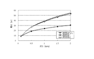
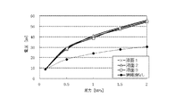
- FIG. 6 is a diagram showing the relationship between the pressure of the atmosphere in the pressure vessel and the voltage when a flashover occurs, showing the difference in the amount of injected insulating oil.
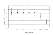
- FIG. 7 is a diagram showing the influence of the load on the insulators of insulating oils having different relative dielectric constants.
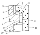
- a ring-shaped packing 28 and a talc 29 are disposed in an annular space formed between the inner peripheral surface of the crimping portion 27 and the tool engaging portion 26 and the outer peripheral surface of the insulator 2, and the insulator 2 is a metal shell. 4 is fixed.
- a middle cylinder part 30 surrounding the middle body part 15 of the insulator 2 is formed on the tip side from the gas seal part 24, and a shelf part 8 protruding radially inward is formed on the tip side from the middle cylinder part 30,
- a front tube portion 31 that surrounds the leg length portion 16 of the insulator 2 is formed on the tip side from the shelf portion 8.
- the insulating oil is a liquid having a volume resistivity at 80 ° C. of 1.0 ⁇ 10 8 ( ⁇ ⁇ cm) or more, and for example, mineral oil, alkylbenzene, polybutene, anaalkylnaphthalene, described in JIS C 2320, Examples thereof include electrical insulating oils such as alkyldiphenylalkanes and silicone oils.
- the dielectric constant of the insulating oil is preferably 5 or less.
- the voltage applied to the insulator 2 can be reduced, and the load on the insulator 2 due to this defect determination step can be suppressed.
- the center electrode 3 and the ground electrode 5 are prepared by, for example, using a vacuum melting furnace to prepare a molten alloy having a desired composition, and preparing ingots from the respective melts by vacuum casting.
- the center electrode 3 and the ground electrode 5 can be manufactured by plastic processing or the like and appropriately adjusted to a predetermined shape and a predetermined dimension. It is also possible to insert the inner material into the cup-shaped outer material and form the center electrode 3 by plastic processing such as extrusion.
- a melting material obtained by melting a chip material having a desired composition is processed into a plate material, and this plate material is punched into a predetermined chip shape by hot punching to produce a noble metal chip.
- the noble metal tip is fused and fixed to the center electrode 3 and the ground electrode 5 by resistance welding and / or laser welding or the like.
- Example 3 A test was conducted in the same manner as in Example 2 except that the amount of the insulating oil 1 was changed using the insulating oil 1. The results are shown in FIG. In FIG. 6, the liquid surface 1 is a case where the insulating oil is injected up to the liquid surface including the center in the axis O direction on the inner peripheral surface of the shelf, and the liquid surface 2 is supplied with the insulating oil up to the liquid surface including the tip of the shelf. In this case, the liquid surface 3 is a case where the insulating oil is injected up to the liquid surface including the center of the axial length between the front end of the shelf and the front end of the metal shell. *
Landscapes
- Engineering & Computer Science (AREA)
- Manufacturing & Machinery (AREA)
- Chemical & Material Sciences (AREA)
- Combustion & Propulsion (AREA)
- Spark Plugs (AREA)
Priority Applications (4)
| Application Number | Priority Date | Filing Date | Title |
|---|---|---|---|
| KR1020137025450A KR101457836B1 (ko) | 2011-03-04 | 2012-01-12 | 스파크 플러그의 제조방법 |
| US14/002,128 US8672722B2 (en) | 2011-03-04 | 2012-01-12 | Spark plug manufacturing method |
| CN201280007830.6A CN103348546B (zh) | 2011-03-04 | 2012-01-12 | 火花塞制造方法 |
| EP12754851.9A EP2683041B1 (de) | 2011-03-04 | 2012-01-12 | Verfahren zur herstellung einer zündkerze |
Applications Claiming Priority (2)
| Application Number | Priority Date | Filing Date | Title |
|---|---|---|---|
| JP2011-047261 | 2011-03-04 | ||
| JP2011047261A JP4975172B1 (ja) | 2011-03-04 | 2011-03-04 | スパークプラグの製造方法 |
Publications (1)
| Publication Number | Publication Date |
|---|---|
| WO2012120757A1 true WO2012120757A1 (ja) | 2012-09-13 |
Family
ID=46650199
Family Applications (1)
| Application Number | Title | Priority Date | Filing Date |
|---|---|---|---|
| PCT/JP2012/000145 Ceased WO2012120757A1 (ja) | 2011-03-04 | 2012-01-12 | スパークプラグの製造方法 |
Country Status (6)
| Country | Link |
|---|---|
| US (1) | US8672722B2 (de) |
| EP (1) | EP2683041B1 (de) |
| JP (1) | JP4975172B1 (de) |
| KR (1) | KR101457836B1 (de) |
| CN (1) | CN103348546B (de) |
| WO (1) | WO2012120757A1 (de) |
Families Citing this family (8)
| Publication number | Priority date | Publication date | Assignee | Title |
|---|---|---|---|---|
| JP5739503B2 (ja) | 2012-11-19 | 2015-06-24 | 日本特殊陶業株式会社 | スパークプラグの検査方法及びスパークプラグの製造方法 |
| JP5638683B2 (ja) | 2012-11-19 | 2014-12-10 | 日本特殊陶業株式会社 | スパークプラグの製造方法 |
| JP5921516B2 (ja) | 2013-11-01 | 2016-05-24 | 日本特殊陶業株式会社 | スパークプラグの製造方法 |
| JP6207573B2 (ja) * | 2015-01-30 | 2017-10-04 | 日本特殊陶業株式会社 | スパークプラグ用の絶縁体の検査方法 |
| US10120015B2 (en) | 2015-01-30 | 2018-11-06 | Ngk Spark Plug Co., Ltd. | Method for inspecting insulator for spark plug |
| JP2016173958A (ja) * | 2015-03-18 | 2016-09-29 | 日本特殊陶業株式会社 | スパークプラグの製造方法およびスパークプラグの製造装置 |
| JP6526508B2 (ja) * | 2015-07-21 | 2019-06-05 | 日本特殊陶業株式会社 | スパークプラグの製造方法 |
| JP6708709B2 (ja) * | 2018-08-06 | 2020-06-10 | 日本特殊陶業株式会社 | スパークプラグの検査方法及びスパークプラグの製造方法 |
Citations (4)
| Publication number | Priority date | Publication date | Assignee | Title |
|---|---|---|---|---|
| JP2550790B2 (ja) | 1991-03-18 | 1996-11-06 | 日本電装株式会社 | 絶縁碍子の欠陥検出装置および欠陥検出方法 |
| JP2004108817A (ja) | 2002-09-13 | 2004-04-08 | Denso Corp | 絶縁碍子の欠陥検査方法 |
| DE102007024407A1 (de) * | 2007-05-25 | 2008-11-27 | Robert Bosch Gmbh | Verfahren und Vorrichtung zur Funktionsüberprüfung von Zündkerzen |
| JP2009238667A (ja) * | 2008-03-28 | 2009-10-15 | Ngk Spark Plug Co Ltd | スパークプラグ及びその製造方法 |
Family Cites Families (8)
| Publication number | Priority date | Publication date | Assignee | Title |
|---|---|---|---|---|
| JPH10115424A (ja) * | 1996-01-31 | 1998-05-06 | Ngk Spark Plug Co Ltd | スパークプラグ |
| JP3228159B2 (ja) * | 1996-12-06 | 2001-11-12 | トヨタ自動車株式会社 | エンジンの点火プラグ検査方法 |
| JPH11214120A (ja) * | 1998-01-29 | 1999-08-06 | Ngk Spark Plug Co Ltd | 内燃機関用スパークプラグとその製造方法 |
| BR9904840A (pt) * | 1998-02-27 | 2000-07-25 | Ngk Spark Plug Co | Vela de ignição, isolador de alumina para vela de ignição e seu método de fabricaçã |
| JP4690230B2 (ja) * | 2006-03-16 | 2011-06-01 | 日本特殊陶業株式会社 | 内燃機関用スパークプラグ及びその製造方法 |
| JP4369963B2 (ja) * | 2007-06-22 | 2009-11-25 | 日本特殊陶業株式会社 | スパークプラグ用絶縁体の検査方法 |
| KR100926943B1 (ko) * | 2007-10-24 | 2009-11-17 | 주식회사 유라테크 | 점화 플러그 제조방법 및 그 장치 |
| US8013617B2 (en) * | 2008-03-10 | 2011-09-06 | Ngk Spark Plug Co., Ltd. | Test method and apparatus for spark plug ceramic insulator |
-
2011
- 2011-03-04 JP JP2011047261A patent/JP4975172B1/ja active Active
-
2012
- 2012-01-12 WO PCT/JP2012/000145 patent/WO2012120757A1/ja not_active Ceased
- 2012-01-12 EP EP12754851.9A patent/EP2683041B1/de active Active
- 2012-01-12 CN CN201280007830.6A patent/CN103348546B/zh active Active
- 2012-01-12 US US14/002,128 patent/US8672722B2/en active Active
- 2012-01-12 KR KR1020137025450A patent/KR101457836B1/ko not_active Expired - Fee Related
Patent Citations (4)
| Publication number | Priority date | Publication date | Assignee | Title |
|---|---|---|---|---|
| JP2550790B2 (ja) | 1991-03-18 | 1996-11-06 | 日本電装株式会社 | 絶縁碍子の欠陥検出装置および欠陥検出方法 |
| JP2004108817A (ja) | 2002-09-13 | 2004-04-08 | Denso Corp | 絶縁碍子の欠陥検査方法 |
| DE102007024407A1 (de) * | 2007-05-25 | 2008-11-27 | Robert Bosch Gmbh | Verfahren und Vorrichtung zur Funktionsüberprüfung von Zündkerzen |
| JP2009238667A (ja) * | 2008-03-28 | 2009-10-15 | Ngk Spark Plug Co Ltd | スパークプラグ及びその製造方法 |
Also Published As
| Publication number | Publication date |
|---|---|
| EP2683041B1 (de) | 2019-12-25 |
| KR20130126721A (ko) | 2013-11-20 |
| CN103348546B (zh) | 2015-03-18 |
| CN103348546A (zh) | 2013-10-09 |
| EP2683041A4 (de) | 2015-03-11 |
| US8672722B2 (en) | 2014-03-18 |
| EP2683041A1 (de) | 2014-01-08 |
| KR101457836B1 (ko) | 2014-11-04 |
| JP2012185963A (ja) | 2012-09-27 |
| US20130337717A1 (en) | 2013-12-19 |
| JP4975172B1 (ja) | 2012-07-11 |
Similar Documents
| Publication | Publication Date | Title |
|---|---|---|
| JP4975172B1 (ja) | スパークプラグの製造方法 | |
| JP5719419B2 (ja) | 点火プラグ及びその製造方法 | |
| WO2014013723A1 (ja) | スパークプラグ | |
| WO2012039090A1 (ja) | スパークプラグ | |
| KR101822723B1 (ko) | 점화 플러그 | |
| KR101665900B1 (ko) | 점화 플러그 | |
| JP5525575B2 (ja) | スパークプラグ | |
| JP5595563B1 (ja) | スパークプラグ | |
| EP2226912B1 (de) | Zündkerze | |
| JP6158283B2 (ja) | スパークプラグ | |
| JP5449581B2 (ja) | スパークプラグ | |
| KR101522057B1 (ko) | 스파크 플러그 | |
| US9742157B2 (en) | Spark plug | |
| JP5690702B2 (ja) | スパークプラグ | |
| JP6903717B2 (ja) | 点火プラグ | |
| JP6207573B2 (ja) | スパークプラグ用の絶縁体の検査方法 |
Legal Events
| Date | Code | Title | Description |
|---|---|---|---|
| 121 | Ep: the epo has been informed by wipo that ep was designated in this application |
Ref document number: 12754851 Country of ref document: EP Kind code of ref document: A1 |
|
| WWE | Wipo information: entry into national phase |
Ref document number: 14002128 Country of ref document: US |
|
| NENP | Non-entry into the national phase |
Ref country code: DE |
|
| ENP | Entry into the national phase |
Ref document number: 20137025450 Country of ref document: KR Kind code of ref document: A |
|
| WWE | Wipo information: entry into national phase |
Ref document number: 2012754851 Country of ref document: EP |