EP2683221A1 - Dispositif et procédé destinés à la commande de diodes lumineuses dépendant de l'amplitude de la tension alimentaire, en utilisant capaciteur et interrupteur - Google Patents
Dispositif et procédé destinés à la commande de diodes lumineuses dépendant de l'amplitude de la tension alimentaire, en utilisant capaciteur et interrupteur Download PDFInfo
- Publication number
- EP2683221A1 EP2683221A1 EP13169481.2A EP13169481A EP2683221A1 EP 2683221 A1 EP2683221 A1 EP 2683221A1 EP 13169481 A EP13169481 A EP 13169481A EP 2683221 A1 EP2683221 A1 EP 2683221A1
- Authority
- EP
- European Patent Office
- Prior art keywords
- voltage
- segment
- led
- capacitor
- current
- Prior art date
- Legal status (The legal status is an assumption and is not a legal conclusion. Google has not performed a legal analysis and makes no representation as to the accuracy of the status listed.)
- Withdrawn
Links
- 239000003990 capacitor Substances 0.000 title claims abstract description 80
- 238000000034 method Methods 0.000 title claims abstract description 29
- 230000001419 dependent effect Effects 0.000 title 1
- 102100025745 Cerberus Human genes 0.000 description 24
- 101000914195 Homo sapiens Cerberus Proteins 0.000 description 24
- 230000008569 process Effects 0.000 description 11
- 230000006978 adaptation Effects 0.000 description 6
- 101710170230 Antimicrobial peptide 1 Proteins 0.000 description 2
- 230000033228 biological regulation Effects 0.000 description 2
- 230000008859 change Effects 0.000 description 2
- 230000007423 decrease Effects 0.000 description 2
- 238000007599 discharging Methods 0.000 description 2
- 230000004907 flux Effects 0.000 description 2
- 230000011218 segmentation Effects 0.000 description 2
- UKGJZDSUJSPAJL-YPUOHESYSA-N (e)-n-[(1r)-1-[3,5-difluoro-4-(methanesulfonamido)phenyl]ethyl]-3-[2-propyl-6-(trifluoromethyl)pyridin-3-yl]prop-2-enamide Chemical compound CCCC1=NC(C(F)(F)F)=CC=C1\C=C\C(=O)N[C@H](C)C1=CC(F)=C(NS(C)(=O)=O)C(F)=C1 UKGJZDSUJSPAJL-YPUOHESYSA-N 0.000 description 1
- 230000006866 deterioration Effects 0.000 description 1
- 238000005265 energy consumption Methods 0.000 description 1
- 230000006872 improvement Effects 0.000 description 1
- 230000002452 interceptive effect Effects 0.000 description 1
- 230000010355 oscillation Effects 0.000 description 1
- 230000002035 prolonged effect Effects 0.000 description 1
- 230000005855 radiation Effects 0.000 description 1
- 230000009467 reduction Effects 0.000 description 1
- 230000004044 response Effects 0.000 description 1
- 230000002441 reversible effect Effects 0.000 description 1
- 230000000630 rising effect Effects 0.000 description 1
- 238000004904 shortening Methods 0.000 description 1
- HODRFAVLXIFVTR-RKDXNWHRSA-N tevenel Chemical compound NS(=O)(=O)C1=CC=C([C@@H](O)[C@@H](CO)NC(=O)C(Cl)Cl)C=C1 HODRFAVLXIFVTR-RKDXNWHRSA-N 0.000 description 1
Images



Classifications
-
- H—ELECTRICITY
- H05—ELECTRIC TECHNIQUES NOT OTHERWISE PROVIDED FOR
- H05B—ELECTRIC HEATING; ELECTRIC LIGHT SOURCES NOT OTHERWISE PROVIDED FOR; CIRCUIT ARRANGEMENTS FOR ELECTRIC LIGHT SOURCES, IN GENERAL
- H05B45/00—Circuit arrangements for operating light-emitting diodes [LED]
- H05B45/40—Details of LED load circuits
- H05B45/44—Details of LED load circuits with an active control inside an LED matrix
- H05B45/48—Details of LED load circuits with an active control inside an LED matrix having LEDs organised in strings and incorporating parallel shunting devices
-
- H—ELECTRICITY
- H05—ELECTRIC TECHNIQUES NOT OTHERWISE PROVIDED FOR
- H05B—ELECTRIC HEATING; ELECTRIC LIGHT SOURCES NOT OTHERWISE PROVIDED FOR; CIRCUIT ARRANGEMENTS FOR ELECTRIC LIGHT SOURCES, IN GENERAL
- H05B45/00—Circuit arrangements for operating light-emitting diodes [LED]
- H05B45/30—Driver circuits
- H05B45/37—Converter circuits
-
- H—ELECTRICITY
- H05—ELECTRIC TECHNIQUES NOT OTHERWISE PROVIDED FOR
- H05B—ELECTRIC HEATING; ELECTRIC LIGHT SOURCES NOT OTHERWISE PROVIDED FOR; CIRCUIT ARRANGEMENTS FOR ELECTRIC LIGHT SOURCES, IN GENERAL
- H05B45/00—Circuit arrangements for operating light-emitting diodes [LED]
- H05B45/30—Driver circuits
- H05B45/395—Linear regulators
- H05B45/397—Current mirror circuits
-
- H—ELECTRICITY
- H05—ELECTRIC TECHNIQUES NOT OTHERWISE PROVIDED FOR
- H05B—ELECTRIC HEATING; ELECTRIC LIGHT SOURCES NOT OTHERWISE PROVIDED FOR; CIRCUIT ARRANGEMENTS FOR ELECTRIC LIGHT SOURCES, IN GENERAL
- H05B45/00—Circuit arrangements for operating light-emitting diodes [LED]
- H05B45/40—Details of LED load circuits
- H05B45/44—Details of LED load circuits with an active control inside an LED matrix
- H05B45/46—Details of LED load circuits with an active control inside an LED matrix having LEDs disposed in parallel lines
-
- H—ELECTRICITY
- H05—ELECTRIC TECHNIQUES NOT OTHERWISE PROVIDED FOR
- H05B—ELECTRIC HEATING; ELECTRIC LIGHT SOURCES NOT OTHERWISE PROVIDED FOR; CIRCUIT ARRANGEMENTS FOR ELECTRIC LIGHT SOURCES, IN GENERAL
- H05B45/00—Circuit arrangements for operating light-emitting diodes [LED]
- H05B45/10—Controlling the intensity of the light
-
- H—ELECTRICITY
- H05—ELECTRIC TECHNIQUES NOT OTHERWISE PROVIDED FOR
- H05B—ELECTRIC HEATING; ELECTRIC LIGHT SOURCES NOT OTHERWISE PROVIDED FOR; CIRCUIT ARRANGEMENTS FOR ELECTRIC LIGHT SOURCES, IN GENERAL
- H05B45/00—Circuit arrangements for operating light-emitting diodes [LED]
- H05B45/30—Driver circuits
- H05B45/355—Power factor correction [PFC]; Reactive power compensation
-
- Y—GENERAL TAGGING OF NEW TECHNOLOGICAL DEVELOPMENTS; GENERAL TAGGING OF CROSS-SECTIONAL TECHNOLOGIES SPANNING OVER SEVERAL SECTIONS OF THE IPC; TECHNICAL SUBJECTS COVERED BY FORMER USPC CROSS-REFERENCE ART COLLECTIONS [XRACs] AND DIGESTS
- Y02—TECHNOLOGIES OR APPLICATIONS FOR MITIGATION OR ADAPTATION AGAINST CLIMATE CHANGE
- Y02B—CLIMATE CHANGE MITIGATION TECHNOLOGIES RELATED TO BUILDINGS, e.g. HOUSING, HOUSE APPLIANCES OR RELATED END-USER APPLICATIONS
- Y02B20/00—Energy efficient lighting technologies, e.g. halogen lamps or gas discharge lamps
- Y02B20/30—Semiconductor lamps, e.g. solid state lamps [SSL] light emitting diodes [LED] or organic LED [OLED]
Definitions
- the invention relates to an arrangement for driving light-emitting diodes, having an input to which an input AC voltage can be applied and connected to the outputs of the arrangement for driving LEDs connected chain of series-connected LEDs, which is divided into at least two segments and each Segment of the chain is connected at one end at least indirectly connected to a constant current source.
- the invention also relates to a method for driving light-emitting diodes, in which a chain of series-connected light-emitting diodes is divided into segments, each segment may include a plurality of light-emitting diodes and having a first terminal and a second terminal and wherein the chain a rectified input AC voltage (VDC) is operated such that the segments (in dependence on the amplitude of the input AC voltage (VDC) and sequentially switched on and off.
- VDC rectified input AC voltage
- LEDs Light Emitting Diode, LED
- LED Light Emitting Diode
- circuit measures must be taken in order to produce the required constant direct current with the low voltage of typically 3... 4 V per LED from a supplying high alternating voltage, which may be for example 230 VAC , These values are typically valid for so-called white LEDs and may differ for other LEDs.
- the LED chain can be divided into segments, which are energized individually or in series according to the instantaneous AC voltage.
- the number of series-connected LEDs and thus the forward voltage of the entire LED chain is designed so that it corresponds to a significant proportion of the amplitude of the mains voltage, which may for example be in the range of 80 to 90% of the amplitude of the mains voltage.
- the voltage drop across the linear current source is thus kept low, resulting in a relatively high efficiency.
- a lower instantaneous voltage only a part of the LED chain, corresponding to the array-side segmentation of the LEDs, also with relatively low voltage drop across the associated power source driven.
- the flow angle is increased within half a mesh period, resulting in a more uniform light output.
- the current of the linear current source or current sources may be modulated according to the instantaneous mains voltage to increase the "power factor", ie, to minimize the harmonic content of the supply current.
- a fundamental disadvantage is the high waviness of the light output with twice the mains frequency, which is perceived by sensitive persons as disturbing. Even with a constant current supply to the LEDs, the light output is reduced if fewer segments than in the LED chain arranged, are active.
- Another circuit disadvantage of the control is that the switching thresholds of the individual segments to the number of LEDs per segment and the actual forward voltage must be adjusted.
- the object of the invention is to provide an arrangement and a method for driving light-emitting diodes, whereby an improved control of the LEDs without deterioration of the efficiency and / or the harmonic content is achieved.
- a capacitance is arranged in a series connection with an electronic switch between one end of a first segment (eg LED-S3) and the constant current source, wherein a first terminal of the capacitor with the End and a second terminal of the capacitance are connected to the switch, that the switch for driving is connected to a control unit, that the second terminal of the capacitance via another switch with the constant current source and with one end of the segment following the first segment (z. B. LED-S4) is connected and that the further switch for driving is connected to a further control unit.
- a first segment eg LED-S3
- the constant current source e.g LED-S3
- the capacitance CER is charged via the input AC input voltage VDC, the LED segment LED-S1, the capacitor CER itself, the closed electronic switch TCC and the constant current source ILED connected to the second input GND of the drive arrangement 1 and the ground potential is connected.
- This charging process begins in the event that the input AC voltage VDC has exceeded the forward voltage of the segment LED-S1.
- the potential in the node VCER also increases between the capacitor CER and the electronic switch TCC, which shuts off the between the end of the first segment LED-S1 and the constant current source ILED arranged switch TC1 leads.
- the charge of the capacitor CER is continued until the forward voltage of the segments LED-S1 and LED-S2 is exceeded. In this case, the switch TCC is opened and the charge remains on the capacitor CER.
- the opening of the switch TCC is advantageous for the realization of the invention per se, but not absolutely necessary.
- the charge accumulated on the CER capacitance is used to close the power gaps that occur at twice the mains frequency. These occur when the input AC voltage VDC drops below the forward voltage of a single segment.
- the arrangement is dimensioned so that the voltage V CER on the capacitor CER is greater than the forward voltage of an LED segment.
- the capacitor is then connected by means of suitable switches (TER) with an LED segment (LED-S4) or only with one or more LEDs within the LED segment, wherein the capacitor CER via the LED segment or the LEDs discharges and these light up.
- Another option is to use one Current limiting or current control arrangement in the discharge circuit. In this way, by adapted dimensioning of the current regulation, the energy stored in the capacitor or the capacitors is emitted evenly and as far as the forward voltage of the LEDs permits it completely during the current gap. In addition, such a regulation of the brightness and the duration of the LEDs is possible.
- a second capacitor is arranged in a second series circuit with an electronic switch between one end of a subsequent segment and the constant current source.
- a second capacitance is introduced into the arrangement, which is also charged in the event that the amplitude of the input AC voltage VDC is large enough.
- an LED segment can also be operated in the event of a current gap so that a voltage V CER1 or V CER2 on a single capacitance does not reach the magnitude of the forward voltage of the LED segment.
- only one LED or several LEDs within an LED segment can also be operated in this embodiment.
- the method provides for a charging of a charging capacitor above a threshold value. For this purpose, a comparison between the input AC voltage and the switch-on threshold, which was previously assigned a voltage value, take place. However, the method does not necessarily require this comparison. Alternatively, it is achieved by connecting a charging capacitor at one end of an LED segment, that after reaching the forward voltage for the element concerned not only a current flow through the segment (LED-S1) itself and its other circuit elements, but also a charging current for the Capacity CE is generated. For this purpose, the end of the segment LED-S1 is connected via a closed switch TC1 to a constant current source ILED. Parallel to this, the capacitance CER is also connected to this constant current source ILED via a closed switch TCC. By means of a suitable control of the switches TC1 and TCC it is ensured that also subsequent LED segments (LED-S2, LED-S3,...) Can be operated with increasing input AC voltage VDC and that the charge can be held on the capacitor CER.
- the charged capacitor CER is connected to an LED segment such that the charge of the capacitor CER discharges through the LEDs of the segment and through this Discharge current, a light emission of the LEDs takes place.
- the switch-on threshold is at a higher voltage value of the input AC voltage (VDC) than the second switching threshold.
- the method can detect the drop below the forward voltage of the first segment LED-S1 and thus start the capacitor discharge via this or another segment. To charge the capacitor CER, it is necessary that the input AC voltage (VDC) has exceeded at least the value of the forward voltage of the first segment LED-S1.
- VDC input AC voltage
- the discharge of the capacitance takes place only over part of the LEDs arranged in the segment.
- FIGS. 1 and 2 Two possible implementations of an arrangement 1 for driving light-emitting diodes 5 according to the prior art are shown. Shown are so-called "direct AC LED” driver with four LED segments 6, which are designated by LED-S1 to LED-S4.
- the chain 4 is fed from the rectified mains voltage VDC 2, a ground side current source 8 ILED generating a constant current.
- segment taps 7 will be switched to the common current source 8 ILED according to the instantaneous voltage across the chain 4 by means of the switching elements SW1 to SW3.
- a control unit CRL serves to distribute the current to the number of segments 6 according to the instantaneous voltage.
- the current source 8 ILED can optionally be modulated according to the instantaneous mains voltage VDC.
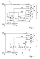
- FIG. 3 shows the principle of the example of three segments 6 LED-S1 to LED-S3 of an LED chain 4 with any number of LEDs 5 in the respective segment 6.
- the number of segments 6 can be arbitrarily increased, which in the figure with a dash -Strich line at the terminal 7 of the segment LED-S3 6 is shown. Likewise, the number of LEDs 5 per segment 6 is freely selectable.
- the anode of the "upper" LED 5 of the segment LED-S1 6 is connected to the supply voltage VDC 2, ie the rectified mains voltage.
- Each segment 6 of the chain 4 has a first and a second terminal 7. In the FIG. 3 the first terminal of the first segment 6 is connected to the voltage VDC. The second terminal 7 of the first segment 6 is connected to the first terminal of the subsequent segment 6 of the chain 4. In addition, this second connection 7 is connected to a switching means 9, 10,.
- the entire LED chain 6 is fed via this switchable and disconnectable switching means 9, 10 from a common ground-side current source 8 ILED.
- ILED common ground-side current source 8
- cascode elements TC1 and TC2 9, 10 formed for example by MOSFETs, bipolar transistors or IGBTs.
- a cascode is the series connection of two transistors, the "lower” transistor (in the case of an n-channel or NPN) assuming control, while the "upper” transistor is used for increasing the dielectric strength and / or the output impedance.
- n stages are formed within the arrangement, which each comprise an n-th LED segment 6 and at least one n-th switching means 9 or 10.
- the first stage comprises the first segment 6 of the chain 4 as well as the first switching means 9.
- an element driving the first switching means 9 may also be included. In the example of FIG. 3 this is a first comparator or amplifier 11 AMP1.
- the cascode elements 9, 10 limit the voltage VQ across the current source 8 and absorb a portion of the difference between the instantaneous VDC and the forward voltage of the active segments 6 of the LED string 4.
- the gate or base voltage VGC applied to the cascode elements 9, 10 determines the maximum voltage VQ. For the automatic threshold adaptation, it is advantageous to keep this voltage low.
- the segment LED-S1 6 will first start to supply current when the forward voltage is reached. If the current limited by the current source 8 has been reached and VQ has reached the value limited by the cascode element 9, 10, the segment voltage VS1 increases as VDC 2 increases further while VQ remains approximately constant.
- comparator 11 With a hysteresis. This applies in particular to the case that relatively high-resistance MOSFETs are used as cascode elements 9, 10. When bipolar transistors are used, their base current must be limited.
- a gradual shutdown such as an amplifier or simple inverter, for example, with moderate gain instead of the comparator.
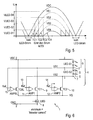
- a transfer of the current through TC2 10 without switching of TC1 9 is also possible by applying a control voltage VG2> VG1, as in FIG. 4 shown.
- VG2> VG1 When the segment LED-S2 6 becomes conductive, TC2 10 increases the voltage VQ and TC1 9 is automatically energized.
- the voltage difference between VG2 14 and VG1 13 must be large enough for TC1 9 to block safely, which must be taken into account in particular when integrating and using relatively high-resistance MOSFETs.
- the LED chain 4 consists of more than two segments 6, the process described is repeated with further increase of VDC 2 for the following stages or current paths n + 1, n + 2 ... etc.
- the chain 4 is not necessarily a cascode element 9, 10 is required, but it is circuitry advantageous for limiting the voltage VQ. This last cascode element 9, 10 does not have to be switched. In the FIG. 3 For example, two cascode elements 9 and 10 are shown.
- the cascode elements 9, 10 are activated again in the reverse order in accordance with the instantaneous voltage with the same circuit.
- FIG. 5 shows the voltage waveforms during a half grid period on the example of an LED chain 4 consisting of four segments 6 with the same number of LEDs 5. It is shown that in the area around the zero crossing of the line-side AC voltage 2 no LED 5 is operated and no LED current flows . In the further course of time of a positive half cycle, the voltage VDC 2 increases until the forward voltages of the LEDs 5 in the segment VLED-S1 6 is reached, current flows through the segment VLED-S1 6 and this segment 6 thus lights up. In the further course of the positive half cycle, the voltage VDC 2 continues to increase until the forward voltages of the LEDs 5 in the segments VLED-S1 6 and VLED-S2 6 are reached. From this point on, current also flows through the segment VLED-S2 6, which now also lights up.
- the embodiment with similar segments 6 may be advantageous for the assembly of an application, but is not a prerequisite for the functionality of the method.
- the voltage drop VQ across the current source 8 has been neglected in the illustration for better understanding.
- the constant current source 8 is shown with a control input, via which the constant current is controllable.
- the current profile of the constant current source can be adapted to the, for example, sinusoidal current characteristic of the rectified pulsating input voltage VDC. This adaptation leads to an improvement of the so-called power factor due to the reduction of interfering harmonics.
- a current path For the operation of an LED lamp on a dimmer which operates by means of a phase-gated (triac) or phase-section method (MOSFET or IGBT), a current path must be provided for charging a capacitor which determines the current flow angle within a half-wave of the mains voltage.
- triac phase-gated
- MOSFET phase-section method
- the previously described circuit 1 will only conduct current when the forward voltage of the first LED segment 6 has been reached and only then can the time-determining capacitor be charged. Without further measures, therefore, the maximum achievable with a dimmer current flow angle is reduced. To avoid this shortening, it is advantageous to have a to set up additional current path, which is already active when the mains voltage VDC is still less than the forward voltage of the first segment 6, for example, LED-S1.
- This current is called “Bleeder Current”, since it is not used to drive the LEDs 5 itself.
- the circuit is off FIG. 4 by a cascode or switching element TCBL 16 and a comparator or amplifier 15 AMPBL have been extended according to the same principle.
- the "bleeder current” continues to flow until VDC has exceeded the forward voltage of segment LED-S1 6. In this case, the voltage VS1 rises and the comparator 15 AMPBL deactivates the "bleeder path". While TCBL 16 is active, the ILED 8 power source provides the bleeder current.
- a "high side” current source can be controlled by a ground-side or a potential-separated current sensor.
- a cascode element 9 carries the current of the current source ILED 8, its voltage drop increases in accordance with the difference between the voltage VDC and the sum voltage of the active segment or segments 6 (LED-S1,. ..) until the next cascode element 10 takes over the current.
- This current flow in the linear region of the element 9 can be used to charge a capacitor 17.
- the charging voltage can be up to the forward voltage of the "next" segment 6 (eg LED-S2), without the Total current and the current flow in the LED segments 6 are affected.
- This charging process may be for a single or for a plurality of cascode elements 9, 10 with a corresponding plurality of capacitors 17, which in the FIG. 7 not shown, are performed.
- the capacitor 17 has not been charged up to the forward voltage of the next segment 6 (eg LED-S2) during the rising edge of the voltage VDC, it can continue to be charged during the falling edge of the voltage VDC, as long as the voltage difference between the instantaneous voltage VDC and the voltage across the capacitor 17 is even greater than the voltage across the capacitor 17 itself.
- the next segment 6 eg LED-S2
- the capacitor 17 behaves like a variable voltage segment.
- the FIG. 7 shows a corresponding circuit detail for an "energy reserve" capacitor CER and two LED segments LED-S1 and LED-S2.
- VDC voltage
- the voltage VS1 rises and the capacitor CER 17 is charged via the cascode element TCC 20.
- the potential in node VCER 19 is also raised and first controller AMP1 11 turns off first switch TC1 9 and the entire current of current source ILED 8 is charged to charge capacitor CER 17 used.
- a linear control of the switches 9, 10 and 20 designed as cascode elements is particularly advantageous here compared to switching with comparators in order to avoid a switching back and forth of the current, for example between the electronic switches TCC 20 and TC1 9.
- the voltage VS2 rises and the charging of the capacitor CER 17 is stopped.
- the switch TC1 9 was either already switched off or is switched off by the rise of the voltage in the node VCER 19. If necessary, the voltage VS2 can also be used additionally to deactivate the switch TC1 9.
- a capacitor 17 it is not absolutely necessary to stop the charging of a capacitor (eg 17) when the next LED segment 6 (eg LED-S2) becomes active, rather a capacitor 17 can also be parallel to two or more segments 6 are loaded. This simplifies the circuitry, but also increases the "Flicker Index", d. H. the relative ripple of the luminous flux, based on the waveform of the total current ILED.
- a second capacitor 18 is additionally arranged in the circuit and charged in the manner described above.
- a portion of the energy stored in the capacitor 17 or in the capacitors 17 and 18 can be used to reduce the ripple of the luminous flux occurring at twice the mains frequency, especially to close the Bestromungslücke, which arises when the voltage VDC below the forward voltage of a single segment 6 (LED-S1) decreases.
- the capacitor voltage is higher than the forward voltage of at least one LED segment 6.
- FIG. 8 A possible arrangement with four segments (LED-S1 to LED-S4) and two capacitors 17 and 18, which are sequentially charged and discharged in series to fill the current gap, shows the FIG. 8 .
- the "Bleeder Current" in the FIG. 8 not considered.
- this can from the FIG. 6 known circuit part in the arrangement of FIG. 8 be used.
- the cascode elements TC1 9, TC2 10 and TC3 21 are first turned on in succession, and the current of the constant current source ILED 8 flows through the segments 6 LED-S1, LED-S1 + LED-S2 and LED-S1 in the same order + LED-S2 + LED-S3. If the voltage VS3 reaches the remaining voltage on the capacitor CER1 17 plus the diode forward voltage of the diode D1 22, a charging current is fed to the capacitor CER1 17 and with a further increase in the voltage VDC, the voltage V CER1 also increases over the capacitor CER1.
- the control unit AMP3 23 controls the switch TC3 21, and the entire current of the current source ILED 8 is for charging the capacitor CER1 17 to disposal.
- the voltage change dVDC / dt is greater than the change dV CER1 / dt in the case of the current ILED 8.
- the capacitor CER1 17 must therefore be chosen to be sufficiently large. If this condition is not fulfilled, the current of the current source ILED 8 is divided between the cascode elements TC3 21 and TCC1 20 and only enough current is used to charge the capacitor CER1 17 that dV CER1 / dt and dVDC / dt are the same. The energization of the LEDs 5 of the segments 6 is not affected thereby.
- the switch TC4 26 takes over again the current of the source ILED 8.
- the cascode element TCC2 27 does not have to be controlled, but can be continuously active. This can be achieved, for example, by connecting the gate of this MOSFET switch 27 to the voltage VGC.
- the diodes D1 22 and D2 25 prevent the discharge of the capacitors CER1 17 and CER2 18 at a falling edge of voltage VDC.
- the charges accumulated in the capacitances CER1 17 and CER2 18 are used by way of example to energize the segment 6 LED-S4 as soon as the voltage VDC enters the range or drops below the forward voltage of segment 6 LED-S1.
- the required control signal is obtained in the same way as described in the control of the "Bleeder Current" already described above and in the associated FIG. 6 was presented.
- the AMPER 28 for power management and AMPBL 15 units may be combined into one unit if desired.
- a level adjusting stage LS 29 controls, with a control signal CRLER, a switching element TER 30 which connects the capacitors CER1 17 and CER2 18 in series. From the sum voltage of the two capacitors 17 and 18, the segment 6 LED-S4 is now fed.
- the current is defined by a current source IER 31.
- the current source IER 31 can be arranged anywhere in the discharge path.
- the discharge of the capacitors 17 and 18 connected in series by means of the switch TER 30 takes place starting from the first terminal of the capacitor 17 via the LEDs 5 of the segment LED-S4 6 and the fifth switch TC4 26, the sixth switch TCC2 27 to the second terminal of the second Capacitor CER2 18 and from the first terminal of this capacitor 18 further via the current source IER 31, the switching element TER 30 to the second terminal of the first capacitor 17th
- a circuit summary of the current source IER 31 with the switching element TER 30 may be advantageous in particular for an integrated solution.
- the dimensioning of the constant current source for the discharge current IER 31 should be such that at minimum supply voltage VDC, the sum voltage at the end of the discharge process is just higher than the forward voltage of the segment 6 LED-S4. This ensures that the current remains constant at the maximum level throughout the entire gap and that the efficiency of the circuit is maximized in relation to the selected topology of the LEDs 5.
- the discharging process ends when the voltage VDC is again high enough for the segment 6 LED-S1 to be energized.
- An extended discharge on both sides may be useful if the current of the source ILED 8 to improve the "Power Factor", ie to reduce the harmonic content in the mains current in response to the instantaneous voltage VDC is controlled and the current in segment 6 LED-S1 first smaller than the current of the source IER 31. Since the available charge in the capacitances CER1 17 and CER2 18 is limited, the current of the source IER 31 must be reduced when the discharge time is prolonged.
Landscapes
- Circuit Arrangement For Electric Light Sources In General (AREA)
- Led Devices (AREA)
Priority Applications (7)
| Application Number | Priority Date | Filing Date | Title |
|---|---|---|---|
| EP13169481.2A EP2683221A1 (fr) | 2012-07-04 | 2013-05-28 | Dispositif et procédé destinés à la commande de diodes lumineuses dépendant de l'amplitude de la tension alimentaire, en utilisant capaciteur et interrupteur |
| TW102122087A TW201406197A (zh) | 2012-07-04 | 2013-06-21 | 控制led之裝置及方法 |
| PCT/EP2013/063808 WO2014005980A1 (fr) | 2012-07-04 | 2013-07-01 | Système et procédé permettant de commander des diodes électroluminescentes en fonction du niveau de tension d'entrée, au moyen de condensateurs et de commutateurs |
| US14/412,234 US20150181666A1 (en) | 2012-07-04 | 2013-07-01 | Arrangement and method for controlling light-emitting diodes in accordance with an input voltage level, by means of a capacitor and switch |
| KR1020157003077A KR20150036392A (ko) | 2012-07-04 | 2013-07-01 | 캐패시터 및 스위치에 의해 입력 전압 레벨에 따라 발광 다이오드들을 제어하기 위한 어레인지먼트 및 방법 |
| CN201380035557.2A CN104584687A (zh) | 2012-07-04 | 2013-07-01 | 借助电容器和开关用于根据输入电压电平控制发光二极管的装置和方法 |
| JP2015519168A JP2015525962A (ja) | 2012-07-04 | 2013-07-01 | コンデンサとスイッチとによって、入力電圧レベルに応じて複数の発光ダイオードを駆動させるための装置及び方法 |
Applications Claiming Priority (3)
| Application Number | Priority Date | Filing Date | Title |
|---|---|---|---|
| EP12174995 | 2012-07-04 | ||
| DE102013100992 | 2013-01-31 | ||
| EP13169481.2A EP2683221A1 (fr) | 2012-07-04 | 2013-05-28 | Dispositif et procédé destinés à la commande de diodes lumineuses dépendant de l'amplitude de la tension alimentaire, en utilisant capaciteur et interrupteur |
Publications (1)
| Publication Number | Publication Date |
|---|---|
| EP2683221A1 true EP2683221A1 (fr) | 2014-01-08 |
Family
ID=48325392
Family Applications (3)
| Application Number | Title | Priority Date | Filing Date |
|---|---|---|---|
| EP13165730.6A Withdrawn EP2683220A1 (fr) | 2012-04-29 | 2013-04-29 | Dispositif et procédé destinés à la commande de diodes lumineuses dépendant de l'amplitude de la tension alimentaire, en utilisant commutateurs de dérivation |
| EP13169481.2A Withdrawn EP2683221A1 (fr) | 2012-07-04 | 2013-05-28 | Dispositif et procédé destinés à la commande de diodes lumineuses dépendant de l'amplitude de la tension alimentaire, en utilisant capaciteur et interrupteur |
| EP13172770.3A Withdrawn EP2683223A1 (fr) | 2012-07-04 | 2013-06-19 | Procédé de commande de diodes lumineuses, obtenant le courant alternatif en phase avec la tension d'alimentation alternative |
Family Applications Before (1)
| Application Number | Title | Priority Date | Filing Date |
|---|---|---|---|
| EP13165730.6A Withdrawn EP2683220A1 (fr) | 2012-04-29 | 2013-04-29 | Dispositif et procédé destinés à la commande de diodes lumineuses dépendant de l'amplitude de la tension alimentaire, en utilisant commutateurs de dérivation |
Family Applications After (1)
| Application Number | Title | Priority Date | Filing Date |
|---|---|---|---|
| EP13172770.3A Withdrawn EP2683223A1 (fr) | 2012-07-04 | 2013-06-19 | Procédé de commande de diodes lumineuses, obtenant le courant alternatif en phase avec la tension d'alimentation alternative |
Country Status (7)
| Country | Link |
|---|---|
| US (2) | US20150156841A1 (fr) |
| EP (3) | EP2683220A1 (fr) |
| JP (2) | JP2015525962A (fr) |
| KR (2) | KR20150036392A (fr) |
| CN (2) | CN104604333A (fr) |
| TW (3) | TW201410070A (fr) |
| WO (3) | WO2014005981A1 (fr) |
Cited By (1)
| Publication number | Priority date | Publication date | Assignee | Title |
|---|---|---|---|---|
| EP3198993A4 (fr) * | 2014-09-23 | 2017-09-06 | Huizhou Light Engine Ltd. | Procédé et circuit de commande de diodes électroluminescentes à partir d'une source de courant triphasé |
Families Citing this family (21)
| Publication number | Priority date | Publication date | Assignee | Title |
|---|---|---|---|---|
| DE102014200433A1 (de) * | 2014-01-13 | 2015-07-16 | Tridonic Jennersdorf Gmbh | Schaltungsanordnung für LED-Betriebsstränge |
| DE102014202363A1 (de) * | 2014-02-10 | 2015-08-13 | Tridonic Gmbh & Co Kg | Spannungskonverter für den Betrieb von Leuchtmitteln |
| US20150382409A1 (en) * | 2014-06-28 | 2015-12-31 | Microchip Technology Inc. | Sequential linear led driver utilizing headroom control |
| JP6403494B2 (ja) * | 2014-08-26 | 2018-10-10 | シチズン時計株式会社 | Led駆動回路 |
| DE102014114853A1 (de) * | 2014-10-14 | 2016-04-14 | Atlas Elektronik Gmbh | Schaltung zum flackerarmen Betreiben von Leuchtdioden, sowie Leuchtmittel und Leuchte |
| US10244596B2 (en) | 2014-10-14 | 2019-03-26 | Seoul Semiconductor Co., Ltd. | LED drive circuit having improved flicker performance and LED lighting device including the same |
| CN107006107B (zh) | 2014-12-12 | 2019-03-29 | 罗姆股份有限公司 | 照明装置 |
| TWI559811B (zh) * | 2015-01-14 | 2016-11-21 | 立錡科技股份有限公司 | 發光元件驅動電路及發光元件電路之驅動方法 |
| TWI616115B (zh) * | 2015-02-12 | 2018-02-21 | Richtek Technology Corp | 線性發光二極體驅動器及其控制方法 |
| CN105992437A (zh) * | 2015-02-13 | 2016-10-05 | 凹凸电子(武汉)有限公司 | 光源驱动电路和光源模块 |
| DE102015207144A1 (de) * | 2015-04-20 | 2016-10-20 | Osram Gmbh | Schaltungsanordnung zum Betreiben mindestens eines ersten und eines zweiten LED-Strangs |
| WO2017015964A1 (fr) * | 2015-07-30 | 2017-02-02 | Tridonic Gmbh & Co Kg | Circuit d'attaque directement en courant alternatif et luminaire |
| FR3039942B1 (fr) * | 2015-08-03 | 2018-08-31 | Aledia | Circuit optoelectronique a diodes electroluminescentes |
| TWM515620U (zh) * | 2015-09-11 | 2016-01-11 | Luxmill Electronic Co Ltd | 可消除電流欠量的多階led驅動電路 |
| US9814105B2 (en) * | 2015-11-12 | 2017-11-07 | Semiconductor Components Industries, Llc | Control circuit for LED and active bleeder thereof |
| CN107801268B (zh) * | 2016-08-31 | 2019-11-15 | 华润矽威科技(上海)有限公司 | 线性高效恒流无频闪led驱动电路及其驱动方法 |
| CN107148127B (zh) * | 2017-07-21 | 2018-06-26 | 肖旭华 | 一种自动检测待测电源或光源调光性能的方法 |
| TWI625987B (zh) * | 2017-08-18 | 2018-06-01 | 鈺瀚科技股份有限公司 | 使用高電壓驅動多個發光二極體的裝置 |
| US11170698B2 (en) * | 2017-11-29 | 2021-11-09 | Planar Systems, Inc. | Active discharge circuitry for display matrix |
| CN112690041B (zh) * | 2018-09-05 | 2023-07-28 | 吉列有限责任公司 | 控制电气设备的用户界面发光元件的照度水平的方法和系统 |
| JP7475351B2 (ja) * | 2018-12-17 | 2024-04-26 | インテレソール エルエルシー | Ac駆動型の発光ダイオードシステム |
Citations (5)
| Publication number | Priority date | Publication date | Assignee | Title |
|---|---|---|---|---|
| DE102010040266A1 (de) * | 2010-03-19 | 2011-09-22 | Active-Semi, Inc. | AC-LED-Leuchte mit reduziertem Flickern und einzeln kurzschliessbaren Abschnitten einer LED-Reihe |
| US20120081009A1 (en) * | 2009-06-04 | 2012-04-05 | Exclara Inc. | Apparatus, Method and System for Providing AC Line Power to Lighting Devices |
| US20120098442A1 (en) * | 2010-10-24 | 2012-04-26 | Microsemi Corporation | Synchronous regulation for led string driver |
| WO2012080890A1 (fr) * | 2010-12-15 | 2012-06-21 | Koninklijke Philips Electronics N.V. | Circuit d'attaque linéaire destiné à réduire la scintillation lumineuse perçue |
| US20120299489A1 (en) * | 2011-05-24 | 2012-11-29 | Nichia Corporation | Light-emitting diode driving device for reducing light off period |
Family Cites Families (15)
| Publication number | Priority date | Publication date | Assignee | Title |
|---|---|---|---|---|
| US7081722B1 (en) * | 2005-02-04 | 2006-07-25 | Kimlong Huynh | Light emitting diode multiphase driver circuit and method |
| JP4588494B2 (ja) * | 2005-03-03 | 2010-12-01 | 株式会社ジャムコ | 照明用発光ダイオード駆動回路 |
| US7723926B2 (en) * | 2006-05-15 | 2010-05-25 | Supertex, Inc. | Shunting type PWM dimming circuit for individually controlling brightness of series connected LEDS operated at constant current and method therefor |
| EP2218305A1 (fr) * | 2007-11-07 | 2010-08-18 | Koninklijke Philips Electronics N.V. | Circuit d'alimentation électrique |
| US8198819B2 (en) * | 2008-09-17 | 2012-06-12 | Switch Bulb Company, Inc. | 3-way LED bulb |
| JP2010109168A (ja) * | 2008-10-30 | 2010-05-13 | Fuji Electric Systems Co Ltd | Led駆動装置、led駆動方法および照明装置 |
| US8174212B2 (en) * | 2008-11-30 | 2012-05-08 | Microsemi Corp.—Analog Mixed Signal Group Ltd. | LED string driver with light intensity responsive to input voltage |
| US8324840B2 (en) * | 2009-06-04 | 2012-12-04 | Point Somee Limited Liability Company | Apparatus, method and system for providing AC line power to lighting devices |
| US8410717B2 (en) * | 2009-06-04 | 2013-04-02 | Point Somee Limited Liability Company | Apparatus, method and system for providing AC line power to lighting devices |
| US8384311B2 (en) * | 2009-10-14 | 2013-02-26 | Richard Landry Gray | Light emitting diode selection circuit |
| JP2012089827A (ja) * | 2010-09-22 | 2012-05-10 | Citizen Holdings Co Ltd | Led駆動回路 |
| TWI444092B (zh) * | 2010-10-05 | 2014-07-01 | Control circuit module for light emitting diode lamps | |
| JP5747656B2 (ja) * | 2011-05-24 | 2015-07-15 | 日亜化学工業株式会社 | 発光ダイオード駆動装置 |
| WO2013089506A1 (fr) * | 2011-12-16 | 2013-06-20 | 서울반도체 주식회사 | Dispositif d'attaque de diode électroluminescente (del) |
| US11178740B2 (en) * | 2011-12-27 | 2021-11-16 | Ideal Industries Lighting Llc | Solid-state lighting apparatus including current diversion controlled by lighting device bias states and current limiting using a passive electrical component |
-
2013
- 2013-04-29 EP EP13165730.6A patent/EP2683220A1/fr not_active Withdrawn
- 2013-05-28 EP EP13169481.2A patent/EP2683221A1/fr not_active Withdrawn
- 2013-06-19 EP EP13172770.3A patent/EP2683223A1/fr not_active Withdrawn
- 2013-06-21 TW TW102122086A patent/TW201410070A/zh unknown
- 2013-06-21 TW TW102122087A patent/TW201406197A/zh unknown
- 2013-06-28 TW TW102123217A patent/TW201410071A/zh unknown
- 2013-07-01 KR KR1020157003077A patent/KR20150036392A/ko not_active Withdrawn
- 2013-07-01 KR KR1020157002844A patent/KR20150036340A/ko not_active Withdrawn
- 2013-07-01 WO PCT/EP2013/063809 patent/WO2014005981A1/fr not_active Ceased
- 2013-07-01 CN CN201380035177.9A patent/CN104604333A/zh active Pending
- 2013-07-01 US US14/411,972 patent/US20150156841A1/en not_active Abandoned
- 2013-07-01 US US14/412,234 patent/US20150181666A1/en not_active Abandoned
- 2013-07-01 JP JP2015519168A patent/JP2015525962A/ja active Pending
- 2013-07-01 WO PCT/EP2013/063808 patent/WO2014005980A1/fr not_active Ceased
- 2013-07-01 WO PCT/EP2013/063811 patent/WO2014005983A1/fr not_active Ceased
- 2013-07-01 JP JP2015519169A patent/JP2015525963A/ja active Pending
- 2013-07-01 CN CN201380035557.2A patent/CN104584687A/zh active Pending
Patent Citations (5)
| Publication number | Priority date | Publication date | Assignee | Title |
|---|---|---|---|---|
| US20120081009A1 (en) * | 2009-06-04 | 2012-04-05 | Exclara Inc. | Apparatus, Method and System for Providing AC Line Power to Lighting Devices |
| DE102010040266A1 (de) * | 2010-03-19 | 2011-09-22 | Active-Semi, Inc. | AC-LED-Leuchte mit reduziertem Flickern und einzeln kurzschliessbaren Abschnitten einer LED-Reihe |
| US20120098442A1 (en) * | 2010-10-24 | 2012-04-26 | Microsemi Corporation | Synchronous regulation for led string driver |
| WO2012080890A1 (fr) * | 2010-12-15 | 2012-06-21 | Koninklijke Philips Electronics N.V. | Circuit d'attaque linéaire destiné à réduire la scintillation lumineuse perçue |
| US20120299489A1 (en) * | 2011-05-24 | 2012-11-29 | Nichia Corporation | Light-emitting diode driving device for reducing light off period |
Cited By (1)
| Publication number | Priority date | Publication date | Assignee | Title |
|---|---|---|---|---|
| EP3198993A4 (fr) * | 2014-09-23 | 2017-09-06 | Huizhou Light Engine Ltd. | Procédé et circuit de commande de diodes électroluminescentes à partir d'une source de courant triphasé |
Also Published As
| Publication number | Publication date |
|---|---|
| TW201406197A (zh) | 2014-02-01 |
| CN104584687A (zh) | 2015-04-29 |
| TW201410070A (zh) | 2014-03-01 |
| US20150181666A1 (en) | 2015-06-25 |
| EP2683220A1 (fr) | 2014-01-08 |
| WO2014005981A1 (fr) | 2014-01-09 |
| KR20150036392A (ko) | 2015-04-07 |
| KR20150036340A (ko) | 2015-04-07 |
| WO2014005980A1 (fr) | 2014-01-09 |
| CN104604333A (zh) | 2015-05-06 |
| TW201410071A (zh) | 2014-03-01 |
| JP2015525963A (ja) | 2015-09-07 |
| US20150156841A1 (en) | 2015-06-04 |
| EP2683223A1 (fr) | 2014-01-08 |
| JP2015525962A (ja) | 2015-09-07 |
| WO2014005983A1 (fr) | 2014-01-09 |
Similar Documents
| Publication | Publication Date | Title |
|---|---|---|
| EP2683221A1 (fr) | Dispositif et procédé destinés à la commande de diodes lumineuses dépendant de l'amplitude de la tension alimentaire, en utilisant capaciteur et interrupteur | |
| DE102010001919B4 (de) | Schaltung und Verfahren zur Ansteuerung eines Leuchtmittels | |
| EP2668822B1 (fr) | Commande de plusieurs sources lumineuses montées en série | |
| EP2345308A1 (fr) | Circuit de fonctionnement destiné à des led | |
| DE202012013514U1 (de) | Beleuchtungsvorrichtung mit lichtemittierenden Halbleiterdioden | |
| EP2522199A2 (fr) | Procédé combiné pour faire fonctionner un élément luminescent électrique et circuit d'exploitation | |
| DE212015000247U1 (de) | LED Antriebskreis mit verbesserter Flimmerleistung und LED Beleuchtungsvorrichtung enthaltend diesen | |
| WO2010049074A1 (fr) | Circuit de commande pour diodes électroluminescentes | |
| AT12464U1 (de) | Betriebsschaltung für leuchtdioden | |
| DE102012007450A1 (de) | Wandler für ein Leuchtmittel, LED-Konverter und Verfahren zum Betreiben eines LLC-Resonanzwandlers | |
| DE102016218552A1 (de) | Getaktete Sperrwandlerschaltung | |
| DE102016206772A1 (de) | Getakteter Wandler für dimmbare Leuchtmittel mit dynamisch einstellbarem Filter | |
| DE112014006816B4 (de) | Adaptiver Leistungsausgleich in LED-Lampen | |
| DE102013211767A1 (de) | Betriebsschaltung für leuchtdioden | |
| WO2010121925A1 (fr) | Dispositif d'éclairage doté d'une fonction d'éclairage variable dans le temps | |
| EP3393207A1 (fr) | Régulateur de commutation destiné au fonctionnement de moyens lumineux à suppression de luminescence résiduelle | |
| EP2667687B1 (fr) | Dispositif de commande de fonctionnement et procédé de fonctionnement d'un agencement de moyen d'éclairage | |
| EP2187707A1 (fr) | Agencement de commutation pour la commande de diodes luminescentes organiques | |
| DE102014005584B4 (de) | LED-Beleuchtungsvorichtung mit einem Energiespeichermodul sowie Verfahren zum Betreiben der LED-Beleuchtungsvorrichtung | |
| EP2395815B1 (fr) | Lampe à DEL et circuit d'excitation ainsi que procédé de fonctionnement d'une lampe | |
| WO2014176608A1 (fr) | Circuit d'exploitation pour diodes électroluminescentes | |
| EP3305024A1 (fr) | Lampe à intensité variable, agencement de circuit ainsi que système d'éclairage | |
| EP3286988A1 (fr) | Agencement de circuit pour faire fonctionner au moins une première et une deuxième ligne de del | |
| WO2015007713A1 (fr) | Dispositif et procédé pour faire fonctionner directement une pluralité de diodes électroluminescentes à une tension continue pulsée | |
| DE202017101093U1 (de) | Schaltregler zum Betreiben von Leuchtmitteln |
Legal Events
| Date | Code | Title | Description |
|---|---|---|---|
| PUAI | Public reference made under article 153(3) epc to a published international application that has entered the european phase |
Free format text: ORIGINAL CODE: 0009012 |
|
| AK | Designated contracting states |
Kind code of ref document: A1 Designated state(s): AL AT BE BG CH CY CZ DE DK EE ES FI FR GB GR HR HU IE IS IT LI LT LU LV MC MK MT NL NO PL PT RO RS SE SI SK SM TR |
|
| AX | Request for extension of the european patent |
Extension state: BA ME |
|
| 17P | Request for examination filed |
Effective date: 20140708 |
|
| RBV | Designated contracting states (corrected) |
Designated state(s): AL AT BE BG CH CY CZ DE DK EE ES FI FR GB GR HR HU IE IS IT LI LT LU LV MC MK MT NL NO PL PT RO RS SE SI SK SM TR |
|
| STAA | Information on the status of an ep patent application or granted ep patent |
Free format text: STATUS: THE APPLICATION IS DEEMED TO BE WITHDRAWN |
|
| 18D | Application deemed to be withdrawn |
Effective date: 20161201 |