EP2683868B1 - Appareil de pressage de linge - Google Patents
Appareil de pressage de linge Download PDFInfo
- Publication number
- EP2683868B1 EP2683868B1 EP12817388.7A EP12817388A EP2683868B1 EP 2683868 B1 EP2683868 B1 EP 2683868B1 EP 12817388 A EP12817388 A EP 12817388A EP 2683868 B1 EP2683868 B1 EP 2683868B1
- Authority
- EP
- European Patent Office
- Prior art keywords
- rod
- press
- nut
- disk
- load bearing
- Prior art date
- Legal status (The legal status is an assumption and is not a legal conclusion. Google has not performed a legal analysis and makes no representation as to the accuracy of the status listed.)
- Not-in-force
Links
- 239000004744 fabric Substances 0.000 claims description 31
- 238000003825 pressing Methods 0.000 claims description 21
- 230000036316 preload Effects 0.000 claims description 12
- 125000006850 spacer group Chemical group 0.000 claims description 9
- 230000006835 compression Effects 0.000 claims description 2
- 238000007906 compression Methods 0.000 claims description 2
- 239000012530 fluid Substances 0.000 description 13
- 230000007704 transition Effects 0.000 description 7
- XLYOFNOQVPJJNP-UHFFFAOYSA-N water Substances O XLYOFNOQVPJJNP-UHFFFAOYSA-N 0.000 description 6
- 238000010409 ironing Methods 0.000 description 5
- 239000007788 liquid Substances 0.000 description 5
- 239000000463 material Substances 0.000 description 4
- 238000000034 method Methods 0.000 description 4
- 238000005452 bending Methods 0.000 description 2
- 230000006378 damage Effects 0.000 description 2
- 238000005406 washing Methods 0.000 description 2
- 208000027418 Wounds and injury Diseases 0.000 description 1
- 230000001010 compromised effect Effects 0.000 description 1
- 238000010276 construction Methods 0.000 description 1
- 238000001035 drying Methods 0.000 description 1
- 208000014674 injury Diseases 0.000 description 1
- 238000005259 measurement Methods 0.000 description 1
- 239000007787 solid Substances 0.000 description 1
- 239000004753 textile Substances 0.000 description 1
Images



Classifications
-
- F—MECHANICAL ENGINEERING; LIGHTING; HEATING; WEAPONS; BLASTING
- F26—DRYING
- F26B—DRYING SOLID MATERIALS OR OBJECTS BY REMOVING LIQUID THEREFROM
- F26B9/00—Machines or apparatus for drying solid materials or objects at rest or with only local agitation; Domestic airing cupboards
- F26B9/04—Machines or apparatus for drying solid materials or objects at rest or with only local agitation; Domestic airing cupboards in presses or clamping devices
-
- D—TEXTILES; PAPER
- D06—TREATMENT OF TEXTILES OR THE LIKE; LAUNDERING; FLEXIBLE MATERIALS NOT OTHERWISE PROVIDED FOR
- D06F—LAUNDERING, DRYING, IRONING, PRESSING OR FOLDING TEXTILE ARTICLES
- D06F47/00—Apparatus of the press type for expelling water from the linen
- D06F47/02—Apparatus of the press type for expelling water from the linen by a mechanically-actuated ram
Definitions
- the present invention relates to an improved apparatus for pressing fluid (e.g., rinse water) from fabric articles (e.g., laundry). More particularly, the present invention relates to an apparatus for pressing fluid from laundry articles wherein the press frame has a specially configured tie rod arrangement with improved fatigue performance.
- pressing fluid e.g., rinse water
- fabric articles e.g., laundry
- the present invention relates to an apparatus for pressing fluid from laundry articles wherein the press frame has a specially configured tie rod arrangement with improved fatigue performance.
- Laundry presses remove water from washed linen by hydraulically applying pressure. This force is developed by pressurizing a hydraulic ram pressing down on linen held in a pressure vessel. The water is pushed out of the linen into a slotted or apertured plate under the linen.
- the following patents relate generally to laundry presses and like devices. TABLE PATENT NO .
- the primary structure of a laundry press frame provides a bottom and top plate held together with four posts or rods.
- the prior art solid posts or rods are machined to create a top and bottom shoulder and then threaded on both ends. A fastening nut is then applied on the top and bottom.
- the frame has upper and lower plates and a plurality of spacer tubes that hold the plates apart, each tube having a rod provided therein.
- the present invention increases the fatigue life for a laundry press by a factor of 200% to 300%.
- the design of the present invention includes a spool and specially configured full length tie rod.
- a fastening nut has been designed to have an outer slot in its body. This slot distributes the loading in the nut threads evenly across all threads wherein previous designs the loading is only on the first 1 to 3 threads.
- the full length tie rod increases the fatigue by applying a reduced shank profile.
- the reduced shank allows the tie rod under tension and bending loading to stretch freely in the center instead of stretching where the fastening nut holds the threads of the post.
- the present invention provides a press for pressing batches of fabric articles to remove excess fluid therefrom.
- the apparatus includes a frame having upper and lower plates.
- the frame supports a vessel having an interior that is configured to receive a batch of fabric articles therein.
- the frame supports a press having a ram and a disk.
- the disk is supported at the lower end portion of the ram.
- the disk is positioned to engage an upper surface portion of the batch of fabric articles that are contained within the vessel interior.
- the ram and disk are movable between upper and lower positions, the lower position being a pressing position that engages the disk with the fabric articles.
- the frame includes a plurality of rods that connect to the upper and lower plates, spacing the upper and lower plates apart.
- the rods each have upper and lower end portions, each with a diameter that is larger than the diameter of a central portion of the rod that is positioned in between the upper and lower plates. The central portion is spaced away from each of the plates.
- each rod is attached to the upper and lower plates with a connection that includes a threaded portion of the rod and a nut that connects to the threaded portion.
- the nut has an annular slot.
- connection includes a preload ring placed in between the nut and a plate.
- each preload ring has a concavity.
- the nut has a convex portion that registers in the concavity.
- the nut has a load bearing face, a non-load bearing face and a length in between the load bearing face and non-load bearing face.
- the annular slot is closer to the load bearing face than it is to the non-load bearing face. In one embodiment, the annular slot is spaced from the load bearing face a distance of about 1/4 of the length.
- the plates have plate openings that are receptive of rod end portions.
- each rod includes a threaded portion and the fastener includes a nut that connects to the threaded portion.
- the nut has an annular slot.
- the fastener includes a preload ring that is placed in between the nut and a plate.
- each preload ring has a concavity and the nut has a convex portion that registers in a concavity.
- the nut has a load bearing face, a non-load bearing face and a length in between the load bearing face and the non-load bearing face, wherein the annular slot is closer to the load bearing face than the non-load bearing face.
- the annular slot is spaced from the load bearing face a distance of about 1/4 of the length.
- the plates have plate openings that are receptive of the rod end portions.
- each rod has threads that do not connect to a plate.
- Some embodiments relate to a laundry press for pressing a batch of fabric articles to remove excess fluid from the articles, comprising a frame having upper and lower plates, each plate having a plurality of plate openings; the frame supporting a vessel having a vessel bottom and side portion and an interior that is configured to contain a batch of fabric articles; a press supporting a ram having upper and lower ram end portions, the ram including a disk supported at the ram lower end portion; wherein the disk is positioned to engage the batch of articles contained within the vessel interior, wherein the disk fits inside of the vessel side portion; the ram and the disk being movable between upper and lower positions, the lower position being a pressing position that engages the disk with the fabric articles; the frame including a plurality of rods that connect to the upper and lower plates at the plate openings, spacing the upper and lower plates apart, the rods each having upper and lower end portions that are at least partially externally threaded, each with a diameter that is larger than the diameter of a central portion of the rod that is positioned in between the
- each nut has an annular slot.
- connection includes a preload ring placed in between the nut and a plate.
- Some embodiments relate to a laundry press apparatus, comprising a frame having upper and lower plates; a plurality of spacer tubes that hold the plates apart, each tube having a tube bore; the frame supporting a vessel having an interior that is configured to receive a batch of wetted fabric articles therein that have been laundered; a press having an elongated ram and a disk supported at the lower end portion of the ram; wherein the disk is positioned to engage an upper surface portion of the batch of fabric articles that are contained within the vessel interior; the ram and the disk being movable between upper and lower positions, the lower position being a pressing position that engages the disk with the fabric articles; the frame including a plurality of rods that extend to the upper and lower plates, each of the rods occupying a tube bore, each rod having upper and lower rod end portions; and fasteners that apply tension to each rod and wherein each tube is in compression when each rod is tensioned.
- each rod includes a threaded end portion and each fastener includes a nut that connects to a threaded end portion.
- the fastener includes a preload ring that is positioned in between a nut and a plate.
- Some embodiments relate to a press for pressing batches of fabric articles to remove excess fluid therefrom, comprising: a frame having upper and lower plates, each plate having a plurality of plate openings; the frame supporting a vessel having an interior that is configured to receive a batch of fabric articles therein; a press having a ram and a disk supported at the lower end portion of the ram; wherein the disk is positioned to engage an upper surface portion of the batch of articles that are contained within the vessel interior; the ram and the disk being movable between upper and lower positions, the lower position being a pressing position that engages the disk with the fabric articles, compressing the fabric articles in between the disk and the vessel; the frame including a plurality of rods that connect to the upper and lower plates at the plate openings, spacing the upper and lower plates apart, the rods each having upper and lower end portions that are at least partially externally threaded, each with a diameter that is larger than the diameter of a central portion of the rod that is positioned in between the upper and lower plates; wherein the central portion is
- each nut has an annular groove.
- connection includes a ring that is placed in between the nut and a plate.
- each ring has a concavity and the nut has a convex portion that registers in a concavity.
- the nut has a load bearing face, a non-load bearing face and a length in between the load bearing face and the non-load bearing face, wherein the annular groove is closer to the load bearing face than the non-load bearing face.
- the annular groove is spaced from the load bearing face a distance of about 1/4 of the length.
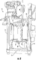
- FIGS 1-14 show a preferred embodiment of the apparatus of the present invention, designated generally by the numeral 10 in figures 8 and 14 .
- the present invention provides a press 10 for pressing batches of fabric articles to remove excess fluid therefrom.
- press 10 employs a pressure cylinder 36 (e.g., hydraulic cylinder) mounted to a machine frame 11.
- a piston rod or push rod 37 extends downwardly from the pressure cylinder 36, supporting a ram 38 that engages the batch of fabric articles which are contained in a shell or vessel 39.
- the present invention provides an improvement to the frame 11 that supports the pressure cylinder 36, pushrod 37, ram 38, and the batch of articles 46 to be pressed with water.
- the apparatus 10 and the improved frame 11 can be seen in Figures 1-7 in more detail.
- FIGS 1A-B, 2 and 8-14 illustrate the frame 11 comprised of top plate 12, bottom plate 13, multiple spacers or spools 14, each housing a reduced shank tie rod 15, and fastening nuts 22, 23 which can be slotted fastening nuts.
- Figures 2-3 illustrate the reduce shank tie rod 15 in more detail.
- the length of the tie rod 15 can be between about 15 and 150 inches (38 and 381 cm).
- the threaded section 26, 27 length on top and bottom can be 12 to 24 inches (30 and 61 cm) with a diameter of between about 3 and 12 inches (8 and 30 cm).
- the reduced shank 30 is generally with a diameter of between about 2 and 10 inches (5 and 25 cm) depending on the diameter of the threaded sections 26, 27.
- the reduced diameter shank 30 will always have a diameter smaller than the diameter of sections 26, 27.
- the assembly shown in Figures 1A-1B and 2 is performed by stretching the tie rod 15 approximately 1/16" to 1/2" (0.16 cm to 1.27 cm) creating the preload which withstands the force of the hydraulic pressure when removing water from the fabric articles or linen.
- the laundry press apparatus 10 thus employs a frame 11 having a top plate or head 12 and a bottom plate 13.
- the bottom plate 13 can be provided with openings, slots or bores through which water can escape.
- a vessel, shell or other container 39 for holding a batch of fabric articles rests upon the bottom plate 13.
- Vessel or shell 39 has interior 45 that holds or contains fabric articles 46 to be pressed of excess fluid.
- the top plate 12 supports a pressure cylinder such as a hydraulic cylinder 36 having a push rod 37 and a ram 38 that engages the fabric articles which care contained within shell or vessel 39.
- the pressure cylinder 36 could typically extend above the top plate 12.
- the top plate 12 provides an opening 16 through which the pushrod or piston rod 37 of the pressure cylinder 36 extends.
- the ram 38 would be positioned in between the plates 12, 13 (see figures 8 and 14 ).
- Each of the top 12 and bottom 13 plates provides four corners, each corner having a rod 15 that is attached to both a top plate 12 and bottom plate 13.
- Figures 2-4 show more particularly the construction of rod 15 and a spacer or spool 14 that extends around each rod 15 as shown.
- a corner 17 is shown for each connection between a rod 15 and top plate 12.
- Figures 2 and 4 also show a connection between a corner 20 of a bottom plate 13. Corner 17 of top plate 12 provides a corner opening 18. Corner 20 of bottom plate 13 provides an opening 21.
- Each rod 15 has a rod upper end 24 and a rod lower end 25.
- the rod upper end 24 provides a larger diameter threaded section 26.
- the rod lower end 25 provides a larger diameter threaded section 27.
- Each rod 15 has a reduced diameter section 30.
- a tapered or transition section 28, 29 is provided in between the rod reduced diameter section 30 and a larger diameter threaded section 26 or 27.
- tapered or transitioned section 28 is a tapered section or transition between reduced diameter section 30 and larger diameter threaded section 26.
- a tapered or transition section 29 is provided in between reduced diameter section 30 and larger diameter threaded section 27.
- An upper nut 22 forms a threaded connection with the larger diameter threaded section 26.
- nut 23 forms a threaded connection with larger diameter threaded section 27.
- Washer 19 is placed in between top plate 12 and nut 22.
- a washer 19 is placed in between nut 23 and bottom plate 13.
- Spacer or spool 14 surrounds rod 15 as shown in figures 1B-4 .
- a washer 19 can be placed in between spacer or spool 14 and top plate 12.
- a washer 19 can be placed in between spacer or spool 14 and bottom plate 13 (See figures 2 and 4).
- Figure 2 shows that the tapered or transition section 28 extends below the connection between nut 22 and top plate 12.
- the transition or tapered section 29 extends above the connection of nut 23 to bottom plate 13.
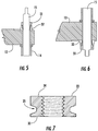
- Figure 5 shows a modified upper joint wherein a tension nut 31 nests in a modified annular member or preload ring 32 which rests against the upper surface of upper plate 12.
- Nut 31 would be internally threaded to connect with external threads on an end portion of rod 15.
- a similar connection could be provided in between lower plate 13 and rod 15 as shown in Figure 6 .
- Figure 7 shows a close up view of nut 22 which has a loading face 33 and an opposing face 34.
- annular groove 35 is closer to the loading face 33 when compared to the opposing face 34 as shown.
- the groove 35 could be about 1/4 of the distance between the loading face 33 and the opposing face 34, being closer to the loading face 33 as shown in Figure 7 .
- Nut 23 could be constructed the same as nut 22 of figure 7 .
- Nuts 22, 23 can have outer flats (e.g., hexagonal shape) so that the nuts can be rotated with a wrench or power tool.
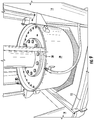
- Nut 22 (or 23) can have openings 47 that are receptive of a tool that could rotate the nut 22 or 23 (See Figure 13 ).
- Figures 8 and 10-11 show retainer 40 which can be used to retain parts of any rod 15 that has failed (e.g., broken into pieces) during use.
- the retainer 40 includes a fitting 42 having internal threads that mate with the external threads 26 of a rod 15. Fitting 42 is placed above nut 22 and threadably attached to threaded section 26. A pair of flanges 41 are attached to fitting 42 using bolted connections 43. The flanges 41 have horizontally extending portions 44 that extend under top plate 12 as seen in figure 10 . If a rod 15 in tension fails, retainer 40 prevents an upper end of the rod 15 from traveling upwardly, becoming a projectile and possibly causing damage or injury.
Landscapes
- Engineering & Computer Science (AREA)
- Mechanical Engineering (AREA)
- Textile Engineering (AREA)
- General Engineering & Computer Science (AREA)
- Accessory Of Washing/Drying Machine, Commercial Washing/Drying Machine, Other Washing/Drying Machine (AREA)
Claims (13)
- Machine de presse pour blanchisserie (10), comprenant :a) un cadre (11) ayant des plaques supérieure et inférieure (12, 13) et une pluralité de tubes d'écartement (14) qui maintiennent les plaques écartées (12, 13), chaque tube (14) ayant un alésage tubulaire ;b) le cadre (11) supportant un récipient (39), ledit récipient (39) dont l'intérieur (45) est configuré pour recevoir un lot d'articles en tissu humidifiés ;c) le cadre (11) supportant une presse, la presse englobant un coulisseau (38) et un disque supporté à la partie d'extrémité inférieure du coulisseau (38) ;d) où le disque est positionné pour s'engager dans une partie de la surface supérieure du lot d'articles qui est contenu à l'intérieur du récipient (45) ;e) le coulisseau (38) et le disque étant mobiles entre une position supérieure et une position inférieure, la position inférieure étant une position de pressage qui engrène le disque avec les articles en tissu ;f) le cadre (11) englobant une pluralité de tiges (15) qui s'étendent jusqu'aux plaques supérieure et inférieure (12, 13), lesdites tiges (15) occupant chacune un dit alésage tubulaire (14), chaque tige (15) ayant des parties d'extrémité de tige supérieure et inférieure (24, 25) ;caractérisée en ce que :g) les parties d'extrémité supérieure et inférieure (24, 25) de chaque tige (15) ont un diamètre supérieur au diamètre d'une partie centrale (30) de la tige (15) qui est située entre les plaques supérieure et inférieure (12, 13) ; eth) des fixations (22, 23, 31) sont fournies pour appliquer une tension à chaque tige (15) et une compression à chaque tube (14).
- Presse (10) selon la revendication 1, où :a) chaque plaque (12, 13) a une pluralité d'ouvertures de plaque (18, 21) ;b) le récipient (39) présente un fond et une partie latérale ;c) le coulisseau (38) présente des parties d'extrémité de coulisseau supérieure et inférieure, le disque étant supporté au niveau de la partie d'extrémité inférieure du coulisseau ;d) le disque s'adapte à l'intérieur de la partie latérale du récipient ;e) la pluralité des tiges (15) se connectent aux plaques supérieure et inférieure (12, 13) au niveau desdites ouvertures de plaques (18, 21), écartant les plaques supérieure et inférieure (12, 13), les parties d'extrémité supérieure et inférieure (24, 25) de chaque tige (15) étant au moins partiellement filetées à l'extérieur (26, 27) ;f) la partie centrale (30) de chaque tige (15) est écartée de chacune des plaques (12 et 13) ; etg) les fixations (22, 23, 31) comprennent une pluralité d'écrous, se fixant chacun à une partie filetée à l'extérieur (26, 27) d'une partie d'extrémité de tige (24, 25).
- Presse (10) selon la revendication 1, où :a) chaque plaque (12, 13) a une pluralité d'ouvertures de plaque (18, 21) ;b) la position inférieure du coulisseau (38) et du disque étant une position de pressage qui engrène le disque avec les articles en tissu, en comprimant les articles en tissu entre le disque et le récipient (39) ;c) la pluralité des tiges (15) se connectent aux plaques supérieure et inférieure (12, 13) au niveau desdites ouvertures de plaques (18, 21), écartant les plaques supérieure et inférieure (12, 13), les parties d'extrémité supérieure et inférieure (24, 25) de chaque tige (15) étant au moins partiellement filetées à l'extérieur (26, 27) ;d) la partie centrale (30) de chaque tige (15) est écartée de chacune des plaques (12 et 13) ; ete) les fixations (22, 23, 31) comprennent une pluralité d'écrous, se fixant chacun à une partie filetée à l'extérieur (26, 27) d'une partie d'extrémité de tige (24, 25).
- Presse (10) selon la revendication 1, où chaque tige (15) comprend une partie filetée (26, 27) et l'élément de fixation (22, 23, 31) comprend un écrou qui se connecte à ladite partie filetée (26, 27).
- Presse (10) selon les revendications 2 ou 4, où l'écrou (22, 23, 31) présente une fente annulaire.
- Presse (10) selon la revendication 3, où chaque écrou (22, 23, 31) présente une rainure annulaire (35).
- Presse (10) selon les revendications 2, 3 ou 4, où l'élément de fixation comprend une bague de précontrainte (32) qui est placé entre ledit écrou (31) et une dite plaque (12, 13).
- Presse (10) selon la revendication 7, où chaque bague de précharge (32) présente une concavité et l'écrou (31) présente une portion convexe qui se loge dans ladite concavité.
- Presse (10) selon les revendications 5 ou 6, où l'écrou (22, 23, 31) présente une face portante, une face non portante et une section entre la face portante et à la face non portante, où la fente annulaire est plus proche de la face portante que de la face non portante.
- Presse (10) selon la revendication 9, où la fente annulaire est espacée de la face portante d'une distance d'environ 1/4 de ladite section.
- Presse (10) selon la revendication 9, où la fente annulaire est espacée de la face portante d'une distance d'environ 1/4 de ladite section.
- Presse (10) selon la revendication 1, où les plaques (12, 13) ont des ouvertures de plaques (18, 21) permettant de recevoir lesdites parties d'extrémité de tige (24, 25).
- Presse (10) selon la revendication 1, où chaque tige (15) présente des filetages (26, 27) qui ne se connectent pas à ladite plaque (12, 13).
Applications Claiming Priority (2)
| Application Number | Priority Date | Filing Date | Title |
|---|---|---|---|
| US201161511791P | 2011-07-26 | 2011-07-26 | |
| PCT/US2012/047219 WO2013016103A1 (fr) | 2011-07-26 | 2012-07-18 | Appareil et procédé de pressage de linge |
Publications (3)
| Publication Number | Publication Date |
|---|---|
| EP2683868A1 EP2683868A1 (fr) | 2014-01-15 |
| EP2683868A4 EP2683868A4 (fr) | 2015-04-22 |
| EP2683868B1 true EP2683868B1 (fr) | 2016-05-18 |
Family
ID=47596027
Family Applications (1)
| Application Number | Title | Priority Date | Filing Date |
|---|---|---|---|
| EP12817388.7A Not-in-force EP2683868B1 (fr) | 2011-07-26 | 2012-07-18 | Appareil de pressage de linge |
Country Status (5)
| Country | Link |
|---|---|
| US (1) | US9920990B2 (fr) |
| EP (1) | EP2683868B1 (fr) |
| JP (2) | JP2014521440A (fr) |
| CN (1) | CN103502524B (fr) |
| WO (1) | WO2013016103A1 (fr) |
Families Citing this family (6)
| Publication number | Priority date | Publication date | Assignee | Title |
|---|---|---|---|---|
| CN102459743B (zh) * | 2009-06-10 | 2014-05-21 | 佩莱若林·米尔诺公司 | 洗熨物挤压设备和方法 |
| US9498850B2 (en) | 2012-03-27 | 2016-11-22 | Pratt & Whitney Canada Corp. | Structural case for aircraft gas turbine engine |
| EP3201383B1 (fr) | 2014-10-03 | 2022-03-09 | Pellerin Milnor Corporation | Procédé pour une laveuse par lot de type continu à tunnel |
| CN106739077B (zh) * | 2017-02-22 | 2018-06-29 | 江苏海狮机械股份有限公司 | 布草压榨机 |
| KR200489401Y1 (ko) * | 2019-04-02 | 2019-06-12 | 전병진 | 연속식 세탁기의 프레스 탈수용 고무통 |
| CN114164592A (zh) * | 2021-12-07 | 2022-03-11 | 浙江龙奇印染有限公司 | 一种服装深度印染环保设备 |
Family Cites Families (46)
| Publication number | Priority date | Publication date | Assignee | Title |
|---|---|---|---|---|
| USRE24257E (en) | 1956-12-18 | Combined washing and squeeze drying machine | ||
| US1359745A (en) | 1918-09-23 | 1920-11-23 | Michael J Reilly | Ironing-machine |
| US1738326A (en) * | 1924-02-23 | 1929-12-03 | Jr Leonard S Smith | Laundering apparatus |
| US1671913A (en) * | 1927-11-02 | 1928-05-29 | Troy Max | Extractor for laundries |
| US1893190A (en) | 1930-10-10 | 1933-01-03 | Robert N West | Ironing machine |
| US2142202A (en) | 1934-01-26 | 1939-01-03 | William T Mckay | Ironing and pressing machine |
| US2538290A (en) * | 1944-11-01 | 1951-01-16 | David F Bernhardt | Electroautomatic laundering machine |
| US2531890A (en) | 1945-04-02 | 1950-11-28 | Louis N Strike | Indexing and lock mechanism |
| US2586292A (en) * | 1945-04-12 | 1952-02-19 | Us Hoffman Machinery Corp | Extractor |
| US2611257A (en) * | 1945-07-28 | 1952-09-23 | Leo M Kahn | Combined washing and squeeze drying machine |
| US2711642A (en) * | 1949-08-04 | 1955-06-28 | Us Hoffman Machinery Corp | Liquid extractor |
| US3071878A (en) | 1961-02-10 | 1963-01-08 | Olson B Beasley | Ironing machine |
| DE1485073A1 (de) * | 1963-04-26 | 1969-04-03 | Passat Maschb Gmbh Frankenbach | Vorrichtung zum Auspressen von nassem Textilgut |
| US3460363A (en) * | 1966-03-04 | 1969-08-12 | Frederick W Grantham | Laundry extractor |
| SU387156A1 (ru) | 1972-02-09 | 1973-06-21 | Авторы изобретени витель | Самоустанавливающийся крепежный узел |
| JPS5256546Y2 (fr) * | 1972-07-26 | 1977-12-21 | ||
| JPS5137141B2 (fr) | 1972-09-05 | 1976-10-14 | ||
| DE2249369C3 (de) * | 1972-10-09 | 1979-01-18 | Josef Dipl.-Ing. 6000 Frankfurt Busek | Presse zum Entwässern von Flächengebilden, wie Lederhäuten |
| DE2311013C3 (de) | 1973-03-06 | 1984-08-30 | Hans F. 7120 Bietigheim-Bissingen Arendt | Taktpresse zur Entwässerung von Naßwäsche |
| ATA753273A (de) | 1973-08-30 | 1975-01-15 | Meyer Arnfried | Balgpresse zum auspressen von fluessigkeit |
| AT345765B (de) | 1976-12-13 | 1978-10-10 | Meyer Arnfried | Anlage zum auspressen von gutposten, insbesondere von waesche |
| SU789283A1 (ru) | 1979-02-16 | 1980-12-23 | Воронежское производственное объединение по выпуску тяжелых механических прессов | Станина механического пресса и способ ее зат жки |
| JPS582654U (ja) * | 1981-06-29 | 1983-01-08 | 大同特殊鋼株式会社 | 引張試験片 |
| CH656653A5 (de) | 1981-08-06 | 1986-07-15 | Kannegiesser H Gmbh Co | Verfahren und vorrichtung zum entwaessern gewaschener waeschestuecke. |
| US4976119A (en) * | 1982-12-22 | 1990-12-11 | Senkingwerke Gmbh & Co. | Piston-type apparatus for expressing water from laundry |
| US4452056A (en) | 1983-04-27 | 1984-06-05 | Pellerin Milnor Corporation | Liquid extracting apparatus |
| DE3341683C2 (de) | 1983-11-18 | 1985-10-31 | Passat-Maschinenbau Gmbh, 7100 Heilbronn | Presse zum Auspressen von Gutposten |
| DE3415856A1 (de) * | 1984-04-28 | 1985-10-31 | Senkingwerk GmbH, 3200 Hildesheim | Verfahren zum entfernen eines entwaesserten waeschepostens aus dem pressbehaelter |
| DE3443123A1 (de) | 1984-05-07 | 1985-11-14 | Herbert Kannegiesser Gmbh + Co, 4973 Vlotho | Verfahren und vorrichtung zum entwaessern gewaschener waeschestuecke |
| JPS6196212A (ja) * | 1984-10-17 | 1986-05-14 | 斉藤 辰夫 | ねじ山の変形ゆるみ止めナツト |
| US4676079A (en) | 1984-10-19 | 1987-06-30 | Herbert Kannegiesser Gmbh & Co. | Appliance for draining washed laundry articles |
| US4574599A (en) | 1984-12-06 | 1986-03-11 | Pallerin Milnor Corporation | Apparatus for pressing liquid from cloth goods |
| DE3506382A1 (de) | 1985-02-23 | 1986-08-28 | Gerhard 7129 Güglingen Engel | Entwaesserungspresse fuer textilien |
| DE8713472U1 (de) | 1987-10-07 | 1988-01-14 | Passat-Maschinenbau Gmbh, 7100 Heilbronn | Kolbenpresse zum Auspressen von Flüssigkeit aus einem Preßgut |
| US5065535A (en) | 1990-06-29 | 1991-11-19 | American Laundry Machinery, Inc. | Indexing system for rotary garment press |
| US5333352A (en) * | 1993-09-07 | 1994-08-02 | Mcdonald Jr William H | Chamois water extraction apparatus |
| US5331755A (en) | 1993-11-03 | 1994-07-26 | The Singer Company Nv | Ironing press with horizontally rotatable pressing members |
| JPH0839299A (ja) * | 1994-07-29 | 1996-02-13 | Hitachi Ltd | プレス機械 |
| US5970637A (en) | 1998-05-29 | 1999-10-26 | American Laundry Machinery, Inc. | Automatic shirt pressing apparatus including a vacuum system and associated method |
| JP2000288800A (ja) * | 1999-04-06 | 2000-10-17 | Ishikawajima Harima Heavy Ind Co Ltd | プレスのコラムのナット締め付け装置 |
| DE10238359A1 (de) * | 2002-08-16 | 2004-03-04 | Herbert Kannegiesser Gmbh | Kolbenpresse |
| DE102006030629B4 (de) | 2005-11-11 | 2009-11-26 | Jensen-Senking Gmbh | Entwässerungspresse zum Entwässern von Wäsche sowie Entwässerungsverfahren |
| JP2008051269A (ja) * | 2006-08-25 | 2008-03-06 | Hard Lock Industry Co Ltd | 緩み止めナット |
| JP4618567B2 (ja) | 2007-02-01 | 2011-01-26 | 勝弘 大内 | 緩み止めナット |
| JP5210715B2 (ja) | 2008-06-06 | 2013-06-12 | 株式会社稲本製作所 | 圧搾式脱水機の脱水方法 |
| CN102459743B (zh) * | 2009-06-10 | 2014-05-21 | 佩莱若林·米尔诺公司 | 洗熨物挤压设备和方法 |
-
2012
- 2012-07-18 WO PCT/US2012/047219 patent/WO2013016103A1/fr not_active Ceased
- 2012-07-18 US US13/552,387 patent/US9920990B2/en active Active
- 2012-07-18 CN CN201280022250.4A patent/CN103502524B/zh not_active Expired - Fee Related
- 2012-07-18 EP EP12817388.7A patent/EP2683868B1/fr not_active Not-in-force
- 2012-07-18 JP JP2014522883A patent/JP2014521440A/ja active Pending
-
2018
- 2018-04-04 JP JP2018071991A patent/JP6634465B2/ja not_active Expired - Fee Related
Non-Patent Citations (1)
| Title |
|---|
| None * |
Also Published As
| Publication number | Publication date |
|---|---|
| EP2683868A1 (fr) | 2014-01-15 |
| US9920990B2 (en) | 2018-03-20 |
| US20130025151A1 (en) | 2013-01-31 |
| JP2014521440A (ja) | 2014-08-28 |
| EP2683868A4 (fr) | 2015-04-22 |
| WO2013016103A1 (fr) | 2013-01-31 |
| JP2018138172A (ja) | 2018-09-06 |
| JP6634465B2 (ja) | 2020-01-22 |
| CN103502524B (zh) | 2016-05-25 |
| CN103502524A (zh) | 2014-01-08 |
Similar Documents
| Publication | Publication Date | Title |
|---|---|---|
| EP2683868B1 (fr) | Appareil de pressage de linge | |
| CN101973136B (zh) | 缸梁一体式液压机 | |
| US9322128B2 (en) | Laundry press apparatus and method | |
| CN104697852A (zh) | 弹簧组件限位拉压循环试验岩石试样固定装置 | |
| US4525935A (en) | Method for dewatering items of washed laundry | |
| US4074890A (en) | Multi-stage hydraulic stretcher for elongated fasteners | |
| CN104596839B (zh) | 十字梁式高压釜上试验机压力平衡装置 | |
| CN206811553U (zh) | 一种摆动式夹紧装置 | |
| DE60205111T2 (de) | Vorrichtung zum färben oder bleichen von garnspulen oder dergleichen | |
| CN102653087A (zh) | 一种自动夹紧拉马 | |
| US11661698B2 (en) | Pressing membrane and a device having such a pressing membrane for dewatering laundry | |
| CN210260050U (zh) | 一种分段式物流辊筒 | |
| KR102448552B1 (ko) | 압력 추출용기의 덮개 클램핑장치 | |
| CN205552087U (zh) | 一种定位模具的支撑结构 | |
| US20110139020A1 (en) | Apparatus for Restraining a Squeezed CRD Blade | |
| CN221495894U (zh) | 一种活塞环压环盖 | |
| CN223893087U (zh) | 一种使用了压机水囊的洗衣龙压榨机 | |
| RU2136502C1 (ru) | Устройство для затяжки разъемной станины пресса и выведения пресса из распора | |
| CN207587522U (zh) | 一种线圈恒压干燥压具 | |
| CN211546955U (zh) | 一种高温高压染色锅用支撑底座 | |
| SU899375A1 (ru) | Станина пресса | |
| CN201329305Y (zh) | 流化床气流粉碎机粉碎筒体的拆装结构改良 | |
| KR920000238Y1 (ko) | 유압을 이용한 프레스 사이드 프레임의 타이로드 체결장치 | |
| RU2011363C1 (ru) | Устройство для установки ротанговой сетки | |
| CN209023460U (zh) | 一种减震化工储存罐 |
Legal Events
| Date | Code | Title | Description |
|---|---|---|---|
| PUAI | Public reference made under article 153(3) epc to a published international application that has entered the european phase |
Free format text: ORIGINAL CODE: 0009012 |
|
| 17P | Request for examination filed |
Effective date: 20131007 |
|
| AK | Designated contracting states |
Kind code of ref document: A1 Designated state(s): AL AT BE BG CH CY CZ DE DK EE ES FI FR GB GR HR HU IE IS IT LI LT LU LV MC MK MT NL NO PL PT RO RS SE SI SK SM TR |
|
| DAX | Request for extension of the european patent (deleted) | ||
| REG | Reference to a national code |
Ref country code: DE Ref legal event code: R079 Ref document number: 602012018770 Country of ref document: DE Free format text: PREVIOUS MAIN CLASS: D06F0047000000 Ipc: D06F0047020000 |
|
| RIC1 | Information provided on ipc code assigned before grant |
Ipc: D06F 47/02 20060101AFI20150312BHEP Ipc: F26B 9/04 20060101ALI20150312BHEP |
|
| RA4 | Supplementary search report drawn up and despatched (corrected) |
Effective date: 20150320 |
|
| GRAP | Despatch of communication of intention to grant a patent |
Free format text: ORIGINAL CODE: EPIDOSNIGR1 |
|
| INTG | Intention to grant announced |
Effective date: 20160222 |
|
| GRAS | Grant fee paid |
Free format text: ORIGINAL CODE: EPIDOSNIGR3 |
|
| GRAA | (expected) grant |
Free format text: ORIGINAL CODE: 0009210 |
|
| AK | Designated contracting states |
Kind code of ref document: B1 Designated state(s): AL AT BE BG CH CY CZ DE DK EE ES FI FR GB GR HR HU IE IS IT LI LT LU LV MC MK MT NL NO PL PT RO RS SE SI SK SM TR |
|
| REG | Reference to a national code |
Ref country code: GB Ref legal event code: FG4D |
|
| REG | Reference to a national code |
Ref country code: CH Ref legal event code: EP |
|
| REG | Reference to a national code |
Ref country code: IE Ref legal event code: FG4D Ref country code: AT Ref legal event code: REF Ref document number: 800575 Country of ref document: AT Kind code of ref document: T Effective date: 20160615 |
|
| REG | Reference to a national code |
Ref country code: DE Ref legal event code: R096 Ref document number: 602012018770 Country of ref document: DE |
|
| REG | Reference to a national code |
Ref country code: NL Ref legal event code: MP Effective date: 20160518 |
|
| REG | Reference to a national code |
Ref country code: LT Ref legal event code: MG4D |
|
| PG25 | Lapsed in a contracting state [announced via postgrant information from national office to epo] |
Ref country code: NO Free format text: LAPSE BECAUSE OF FAILURE TO SUBMIT A TRANSLATION OF THE DESCRIPTION OR TO PAY THE FEE WITHIN THE PRESCRIBED TIME-LIMIT Effective date: 20160818 Ref country code: NL Free format text: LAPSE BECAUSE OF FAILURE TO SUBMIT A TRANSLATION OF THE DESCRIPTION OR TO PAY THE FEE WITHIN THE PRESCRIBED TIME-LIMIT Effective date: 20160518 Ref country code: FI Free format text: LAPSE BECAUSE OF FAILURE TO SUBMIT A TRANSLATION OF THE DESCRIPTION OR TO PAY THE FEE WITHIN THE PRESCRIBED TIME-LIMIT Effective date: 20160518 Ref country code: LT Free format text: LAPSE BECAUSE OF FAILURE TO SUBMIT A TRANSLATION OF THE DESCRIPTION OR TO PAY THE FEE WITHIN THE PRESCRIBED TIME-LIMIT Effective date: 20160518 |
|
| REG | Reference to a national code |
Ref country code: AT Ref legal event code: MK05 Ref document number: 800575 Country of ref document: AT Kind code of ref document: T Effective date: 20160518 |
|
| PG25 | Lapsed in a contracting state [announced via postgrant information from national office to epo] |
Ref country code: LV Free format text: LAPSE BECAUSE OF FAILURE TO SUBMIT A TRANSLATION OF THE DESCRIPTION OR TO PAY THE FEE WITHIN THE PRESCRIBED TIME-LIMIT Effective date: 20160518 Ref country code: PT Free format text: LAPSE BECAUSE OF FAILURE TO SUBMIT A TRANSLATION OF THE DESCRIPTION OR TO PAY THE FEE WITHIN THE PRESCRIBED TIME-LIMIT Effective date: 20160919 Ref country code: RS Free format text: LAPSE BECAUSE OF FAILURE TO SUBMIT A TRANSLATION OF THE DESCRIPTION OR TO PAY THE FEE WITHIN THE PRESCRIBED TIME-LIMIT Effective date: 20160518 Ref country code: ES Free format text: LAPSE BECAUSE OF FAILURE TO SUBMIT A TRANSLATION OF THE DESCRIPTION OR TO PAY THE FEE WITHIN THE PRESCRIBED TIME-LIMIT Effective date: 20160518 Ref country code: HR Free format text: LAPSE BECAUSE OF FAILURE TO SUBMIT A TRANSLATION OF THE DESCRIPTION OR TO PAY THE FEE WITHIN THE PRESCRIBED TIME-LIMIT Effective date: 20160518 Ref country code: GR Free format text: LAPSE BECAUSE OF FAILURE TO SUBMIT A TRANSLATION OF THE DESCRIPTION OR TO PAY THE FEE WITHIN THE PRESCRIBED TIME-LIMIT Effective date: 20160819 Ref country code: SE Free format text: LAPSE BECAUSE OF FAILURE TO SUBMIT A TRANSLATION OF THE DESCRIPTION OR TO PAY THE FEE WITHIN THE PRESCRIBED TIME-LIMIT Effective date: 20160518 |
|
| PG25 | Lapsed in a contracting state [announced via postgrant information from national office to epo] |
Ref country code: IT Free format text: LAPSE BECAUSE OF FAILURE TO SUBMIT A TRANSLATION OF THE DESCRIPTION OR TO PAY THE FEE WITHIN THE PRESCRIBED TIME-LIMIT Effective date: 20160518 Ref country code: BE Free format text: LAPSE BECAUSE OF NON-PAYMENT OF DUE FEES Effective date: 20160731 |
|
| PG25 | Lapsed in a contracting state [announced via postgrant information from national office to epo] |
Ref country code: EE Free format text: LAPSE BECAUSE OF FAILURE TO SUBMIT A TRANSLATION OF THE DESCRIPTION OR TO PAY THE FEE WITHIN THE PRESCRIBED TIME-LIMIT Effective date: 20160518 Ref country code: SK Free format text: LAPSE BECAUSE OF FAILURE TO SUBMIT A TRANSLATION OF THE DESCRIPTION OR TO PAY THE FEE WITHIN THE PRESCRIBED TIME-LIMIT Effective date: 20160518 Ref country code: DK Free format text: LAPSE BECAUSE OF FAILURE TO SUBMIT A TRANSLATION OF THE DESCRIPTION OR TO PAY THE FEE WITHIN THE PRESCRIBED TIME-LIMIT Effective date: 20160518 Ref country code: CZ Free format text: LAPSE BECAUSE OF FAILURE TO SUBMIT A TRANSLATION OF THE DESCRIPTION OR TO PAY THE FEE WITHIN THE PRESCRIBED TIME-LIMIT Effective date: 20160518 Ref country code: RO Free format text: LAPSE BECAUSE OF FAILURE TO SUBMIT A TRANSLATION OF THE DESCRIPTION OR TO PAY THE FEE WITHIN THE PRESCRIBED TIME-LIMIT Effective date: 20160518 |
|
| REG | Reference to a national code |
Ref country code: DE Ref legal event code: R097 Ref document number: 602012018770 Country of ref document: DE |
|
| PG25 | Lapsed in a contracting state [announced via postgrant information from national office to epo] |
Ref country code: SM Free format text: LAPSE BECAUSE OF FAILURE TO SUBMIT A TRANSLATION OF THE DESCRIPTION OR TO PAY THE FEE WITHIN THE PRESCRIBED TIME-LIMIT Effective date: 20160518 Ref country code: PL Free format text: LAPSE BECAUSE OF FAILURE TO SUBMIT A TRANSLATION OF THE DESCRIPTION OR TO PAY THE FEE WITHIN THE PRESCRIBED TIME-LIMIT Effective date: 20160518 Ref country code: BE Free format text: LAPSE BECAUSE OF FAILURE TO SUBMIT A TRANSLATION OF THE DESCRIPTION OR TO PAY THE FEE WITHIN THE PRESCRIBED TIME-LIMIT Effective date: 20160518 Ref country code: AT Free format text: LAPSE BECAUSE OF FAILURE TO SUBMIT A TRANSLATION OF THE DESCRIPTION OR TO PAY THE FEE WITHIN THE PRESCRIBED TIME-LIMIT Effective date: 20160518 |
|
| REG | Reference to a national code |
Ref country code: CH Ref legal event code: PL |
|
| PLBE | No opposition filed within time limit |
Free format text: ORIGINAL CODE: 0009261 |
|
| STAA | Information on the status of an ep patent application or granted ep patent |
Free format text: STATUS: NO OPPOSITION FILED WITHIN TIME LIMIT |
|
| PG25 | Lapsed in a contracting state [announced via postgrant information from national office to epo] |
Ref country code: MC Free format text: LAPSE BECAUSE OF FAILURE TO SUBMIT A TRANSLATION OF THE DESCRIPTION OR TO PAY THE FEE WITHIN THE PRESCRIBED TIME-LIMIT Effective date: 20160518 |
|
| 26N | No opposition filed |
Effective date: 20170221 |
|
| GBPC | Gb: european patent ceased through non-payment of renewal fee |
Effective date: 20160818 |
|
| PG25 | Lapsed in a contracting state [announced via postgrant information from national office to epo] |
Ref country code: LI Free format text: LAPSE BECAUSE OF NON-PAYMENT OF DUE FEES Effective date: 20160731 Ref country code: CH Free format text: LAPSE BECAUSE OF NON-PAYMENT OF DUE FEES Effective date: 20160731 Ref country code: FR Free format text: LAPSE BECAUSE OF NON-PAYMENT OF DUE FEES Effective date: 20160801 |
|
| REG | Reference to a national code |
Ref country code: FR Ref legal event code: ST Effective date: 20170331 |
|
| REG | Reference to a national code |
Ref country code: IE Ref legal event code: MM4A |
|
| PG25 | Lapsed in a contracting state [announced via postgrant information from national office to epo] |
Ref country code: SI Free format text: LAPSE BECAUSE OF FAILURE TO SUBMIT A TRANSLATION OF THE DESCRIPTION OR TO PAY THE FEE WITHIN THE PRESCRIBED TIME-LIMIT Effective date: 20160518 |
|
| PG25 | Lapsed in a contracting state [announced via postgrant information from national office to epo] |
Ref country code: GB Free format text: LAPSE BECAUSE OF NON-PAYMENT OF DUE FEES Effective date: 20160818 Ref country code: IE Free format text: LAPSE BECAUSE OF NON-PAYMENT OF DUE FEES Effective date: 20160718 |
|
| PG25 | Lapsed in a contracting state [announced via postgrant information from national office to epo] |
Ref country code: LU Free format text: LAPSE BECAUSE OF NON-PAYMENT OF DUE FEES Effective date: 20160718 |
|
| PG25 | Lapsed in a contracting state [announced via postgrant information from national office to epo] |
Ref country code: CY Free format text: LAPSE BECAUSE OF FAILURE TO SUBMIT A TRANSLATION OF THE DESCRIPTION OR TO PAY THE FEE WITHIN THE PRESCRIBED TIME-LIMIT Effective date: 20160518 Ref country code: HU Free format text: LAPSE BECAUSE OF FAILURE TO SUBMIT A TRANSLATION OF THE DESCRIPTION OR TO PAY THE FEE WITHIN THE PRESCRIBED TIME-LIMIT; INVALID AB INITIO Effective date: 20120718 |
|
| PG25 | Lapsed in a contracting state [announced via postgrant information from national office to epo] |
Ref country code: TR Free format text: LAPSE BECAUSE OF FAILURE TO SUBMIT A TRANSLATION OF THE DESCRIPTION OR TO PAY THE FEE WITHIN THE PRESCRIBED TIME-LIMIT Effective date: 20160518 Ref country code: IS Free format text: LAPSE BECAUSE OF FAILURE TO SUBMIT A TRANSLATION OF THE DESCRIPTION OR TO PAY THE FEE WITHIN THE PRESCRIBED TIME-LIMIT Effective date: 20160518 Ref country code: MK Free format text: LAPSE BECAUSE OF FAILURE TO SUBMIT A TRANSLATION OF THE DESCRIPTION OR TO PAY THE FEE WITHIN THE PRESCRIBED TIME-LIMIT Effective date: 20160518 Ref country code: MT Free format text: LAPSE BECAUSE OF NON-PAYMENT OF DUE FEES Effective date: 20160731 |
|
| PG25 | Lapsed in a contracting state [announced via postgrant information from national office to epo] |
Ref country code: BG Free format text: LAPSE BECAUSE OF FAILURE TO SUBMIT A TRANSLATION OF THE DESCRIPTION OR TO PAY THE FEE WITHIN THE PRESCRIBED TIME-LIMIT Effective date: 20160518 |
|
| PG25 | Lapsed in a contracting state [announced via postgrant information from national office to epo] |
Ref country code: AL Free format text: LAPSE BECAUSE OF FAILURE TO SUBMIT A TRANSLATION OF THE DESCRIPTION OR TO PAY THE FEE WITHIN THE PRESCRIBED TIME-LIMIT Effective date: 20160518 |
|
| PGFP | Annual fee paid to national office [announced via postgrant information from national office to epo] |
Ref country code: DE Payment date: 20210706 Year of fee payment: 10 |
|
| REG | Reference to a national code |
Ref country code: DE Ref legal event code: R119 Ref document number: 602012018770 Country of ref document: DE |
|
| PG25 | Lapsed in a contracting state [announced via postgrant information from national office to epo] |
Ref country code: DE Free format text: LAPSE BECAUSE OF NON-PAYMENT OF DUE FEES Effective date: 20230201 |