EP2684005B1 - Dispositif de réglage destiné à régler le réticule d'une lunette de visée - Google Patents
Dispositif de réglage destiné à régler le réticule d'une lunette de visée Download PDFInfo
- Publication number
- EP2684005B1 EP2684005B1 EP20110720012 EP11720012A EP2684005B1 EP 2684005 B1 EP2684005 B1 EP 2684005B1 EP 20110720012 EP20110720012 EP 20110720012 EP 11720012 A EP11720012 A EP 11720012A EP 2684005 B1 EP2684005 B1 EP 2684005B1
- Authority
- EP
- European Patent Office
- Prior art keywords
- index ring
- scale values
- adjusting device
- ring
- revolution
- Prior art date
- Legal status (The legal status is an assumption and is not a legal conclusion. Google has not performed a legal analysis and makes no representation as to the accuracy of the status listed.)
- Active
Links
Images



Classifications
-
- G—PHYSICS
- G02—OPTICS
- G02B—OPTICAL ELEMENTS, SYSTEMS OR APPARATUS
- G02B27/00—Optical systems or apparatus not provided for by any of the groups G02B1/00 - G02B26/00, G02B30/00
- G02B27/32—Fiducial marks and measuring scales within the optical system
- G02B27/36—Fiducial marks and measuring scales within the optical system adjustable
-
- F—MECHANICAL ENGINEERING; LIGHTING; HEATING; WEAPONS; BLASTING
- F41—WEAPONS
- F41G—WEAPON SIGHTS; AIMING
- F41G1/00—Sighting devices
- F41G1/38—Telescopic sights specially adapted for smallarms or ordnance; Supports or mountings therefor
Definitions
- the invention relates to an adjusting device for adjusting the reticle device of a telescopic sight with the further features of the preamble of patent claim 1.
- An adjusting device which serves for adjusting a reticle of a telescopic sight.
- the overall tower-like adjusting device has a rotatable adjusting cap, which is coupled via a transmission device to the reticle within the telescopic sight to implement the rotational movement of the adjusting cap in an adjustment movement of the reticle, which is usually linear.
- Such adjusting devices are used to adjust the reticle to different firing distances.
- the range of rotation of the adjusting cap is designed for more than one revolution, ie it comprises approximately two full revolutions.
- the user has the opportunity to read the rotational position of the adjusting cap and thus the adjustment of the reticle to the firing distance on the basis of scale values, which are assigned to the respective rotational ranges.
- An orbiting set of scale values is associated with the first revolution of the adjustment cap, and a second set of scale values disposed above or below the first set is associated with the second revolution region of the adjustment cap.
- the known adjusting device In the known adjusting device, both sets of scale values are always visible. In order for the user to decide which set of scale values will depend on the position of the adjustment cap within a first or second rotation range of the applicable, the known device comprises a tactile indicating means which protrudes from the adjustment device when the adjustment cap is adjusted within the second rotation range ,
- the invention has for its object to form an adjustment with the features of the preamble of claim 1 such that the clarity in the reading of the scale values is improved and the user is supported in terms of error prevention.
- This object is solved by the characterizing features of claim 1, advantageous developments of the invention will become apparent from the dependent claims.
- At least one index ring carrying the scale values and / or an aperture ring partially covering an index ring region is vertically displaceable such that during the first rotation of the adjustment cap only a first set of the scale values is visible and during the second revolution of the adjusting cap or preferably only the second set of scale values is visible.
- a first option is to arrange the first set of scale values on a first index ring and the second set of scale values on a second index ring located within the first index ring, and the first, d. H. outer index ring, offset in height at the transition from the first rotational range of the adjustment cap to the second range of rotation so that the scale values on the second index ring are covered before the height displacement (first rotation range) and only the scale values on the first outer index ring are visible and after the height displacement, d. H. within the second rotation range, looking at scale values located on the second indexing ring is enabled by the first indexing ring and the scale values located on the first indexing ring vanish below an aperture area. It is possible to shift the outer index ring either up or down and provide either the top or bottom of the covering aperture area for the first scale values on the outer index ring.
- first scale values and the second ones Scale values together with at least one bar scale, which may be arranged between the first and second scale values, for example, to provide only one index ring and this shift up or down depending on the range of rotation within a transition region such that once the first set of scale values is covered and alternatively, the second set of scale values is then covered and the other is visible.
- index ring with the two sets of scale values not ably arranged with the two sets of scale values not ably arranged with the two sets of scale values not ably arranged with the two sets of scale values not ably arranged with the two sets of scale values not ably arranged with the two sets of scale values not ably arranged with the two sets of scale values not ably arranged with the two sets of scale values not ably arranged with the two sets of scale values not ably smallerbar and provide on the outside of the index ring upper and lower annular apertures covering the upper or lower set of scale values on the not Multenverlagerbaren index ring depending on the selected range of rotation.
- a combination of height-adjustable panels and height-adjustable index rings is also conceivable.
- the first set of scale values of the first outer index ring is displaced below a downwardly facing edge of the adjusting cap at the transition from the first revolution to the second revolution of the adjusting cap and thereby covered. Due to the height displacement of the first index ring, the lower edge of the first index ring releases the second set of scale values disposed on the non-height-displaceable second index ring disposed within the first index ring.
- the first and the second index ring - whether they are now hereby HANnverlagerbar or not - synchronously rotated with adjusting cap Corresponding to a setting of the absence scale values can be read off an index mark, which is arranged non-rotatably on a base of the adjusting device.
- the adjustment is a total tower-like structure, the base portion of the tower-like structure is used for attachment to the top of a rifle scope, since such finely adjustable adjusting devices are usually used to make a Ab Spurnver ein, as only through this adaptation to different firing distances is possible.
- a circumferential slotted guide is arranged for the vertical displacement of the index rings or at least one orifice, in the one Plunger dips, which can be coupled via intermediate parts or directly with an index ring or aperture.
- the pin will remain in the slotted guide during the first revolution area without vertical displacement and the coupled index ring thereby maintain its altitude. If the pin passes through further rotation to the sliding guide means region, which has a beveled stepped course, the pin will follow this beveled step-like course and thereby cause the vertical displacement of the index ring or diaphragm ring coupled to it.
- the pin Within the second rotation range, the pin then follows the guide groove of the slotted guide which is essentially parallel to the first rotation region, and then a further height displacement no longer takes place within the second rotation range.
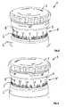
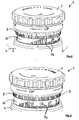
- the adjusting device 1 shown in the drawing figures is used for adjusting the reticle of a not-shown telescopic sight and has a rotatable adjusting cap 2, which is rotatably arranged at the upper end of a total tower-like structure of the adjusting device 1.
- a transmission device 3 is arranged, with which the rotational movement of the adjusting cap 2 is converted into an adjusting movement of the reticle.
- the transmission device 3 is down beyond a base region 4 of the adjusting device 1 addition.
- the range of rotation of the adjusting cap 2 comprises essentially two revolutions, in the central region 5 of the adjusting device 1 two sets of scale values 7 associated with at least one graduated scale 6 are arranged, a first set of scale values 7a indicating adjustment values belonging to the first revolution of the adjusting cap 2 second set of scale values 7b indicates adjustment values belonging to the second revolution of the adjusting cap 2.
- a scale ring 7a carrying, preferably with the adjusting cap 2 synchronously rotatable index ring so essentially arranged under a cover and during the second revolution of the adjusting cap 2, only the associated second set of scale values 7b is visible, the first set of scale values 7a being arranged under a cover.
- Covers may be annular aperture areas, for example, a downwardly depending edge 9 of the adjustment cap 2 located in the region of the upper edge of the index ring 8 and below which edge 9 the first set of scale values 7a dips when the index ring 8 is displaced upwardly ,
- Figure 1-8 is below the in Figures 1 and 2 visible index ring 8
- a second index ring 10 is arranged, which carries the second scale values 7b and which is covered before the switching, ie before the vertical displacement of the index ring 8 from the index ring.
- the first index ring 8 forms, as it were, the cover for the second index ring and the second scale value 7b arranged thereon.
- the height displacement of the first index ring 8 takes place upward, so that the first scale values 7a are brought under the downwardly pointing edge 9 of the adjusting cap. But it is just as possible to shift the outer first index ring when switching from the first to the second rotation range of the adjustment cap down and lower the first scale values 7a below a ring aperture in the region of the base 4.
- a further embodiment lying within the scope of claim 1 provides for arranging both sets of scale values 27a and 27b above and below a graduated scale 26 on an index ring 28.
- This index ring 28 is displaceable upwards and downwards when switching from the first to the second rotation range of the adjusting cap 2, so that once the first index values 27a are visible and once the second index values 27b are visible.
- a further bar scale 26 ' is arranged, which allows a paralax-free reading.
- the index ring 28 is displaced upward during the switching operation, so that the second scale values 27b associated with the second rotation area are selected from one during the first one Turning area concealing lower annular aperture 29 are shifted outwards.
- the lower annular diaphragm 29 forms the upper edge of the base region 4.
- the index ring shown in Figure 10 can also be arranged fixed in terms of its height in the adjustment, the switching then upper and lower apertures, such as the lower annular aperture 29 and an upper annular aperture, as shown in Figure 11, up and shifted down. This also achieves the purpose that only one set of scale values 27a or 27b is visible, so that incorrect settings by the operator of the adjusting device 1 are avoided.
- drawing figure 13 is a perspective view of an inner region of the tower-like structure of the adjusting device 1 is shown.
- a slide guide 40 is rotatably arranged, which has a circumferential slide groove 41 into which a scanning pin 42 (FIG. Fig. 7 ) which engages via coupling elements 43 (cf. FIGS. 7 and 8 ) is coupled to the height-displaceable elements, such as the index ring 8.
- the slide groove 41 has a tapered stage course, so that a scanning pin, the gem in the direction of arrow 45.
- Fig. 13 is brought to the slide guide portion 44, performs an offset movement upwards, which corresponds to the distance between the two circumferential slide grooves 41, whereby it comes to the vertical displacement of the coupled to the pin 42 component, in particular the Multenverlagerbaren index ring 8 or 28.
- an O-ring 50 is provided which seals between the surface of the second index ring 10 and the inside of the first index ring 8.
- Another O-ring 51 seals the upper radially outer region of the first index ring 8 against the inside of the downwardly projecting edge 9 of the adjusting cap 2.
Landscapes
- Physics & Mathematics (AREA)
- Optics & Photonics (AREA)
- Engineering & Computer Science (AREA)
- General Engineering & Computer Science (AREA)
- General Physics & Mathematics (AREA)
- Aiming, Guidance, Guns With A Light Source, Armor, Camouflage, And Targets (AREA)
- Orthopedics, Nursing, And Contraception (AREA)
- Diaphragms For Cameras (AREA)
- Transmission Devices (AREA)
- Prostheses (AREA)
Claims (12)
- Dispositif de réglage (1) destiné à régler le réticule d'une lunette de visée, comprenant un capuchon d'ajustement rotatif (2), un dispositif de transfert (3) pour convertir le mouvement de rotation du capuchon d'ajustement (2) en un mouvement de réglage du réticule, la plage de rotation du capuchon d'ajustement (2) comprenant essentiellement deux rotations, et deux jeux de valeurs d'échelle (7a, 7b, 27a, 27b) associées à au moins une échelle graduée (6) étant disposés au niveau du dispositif de réglage, un premier jeu de valeurs d'échelle (7a, 27a) indiquant des valeurs de réglage qui correspondent à une première rotation du capuchon d'ajustement (2) et un deuxième jeu de valeurs d'échelle (7b, 27b) indiquant des valeurs de réglage qui correspondent à la deuxième rotation du capuchon d'ajustement (2),
caractérisé en ce que
lors de la transition de la première à la deuxième rotation du capuchon d'ajustement, au moins une bague d'indexage (8, 28) portant les valeurs d'échelle (7a, 27a, 27b) et pouvant tourner avec le capuchon d'ajustement (2) ou au moins une bague de diaphragme recouvrant en partie une bague d'indexage peut être déplacée en hauteur de telle sorte que pendant la première rotation du capuchon d'ajustement (2) seulement un premier jeu des valeurs d'échelle (7a, 27a) soit visible et que le deuxième jeu de valeurs d'échelle (7b, 27b) soit disposé sous un recouvrement et que pendant la deuxième rotation du capuchon d'ajustement (2) soit seulement soit également le deuxième jeu associé de valeurs d'échelle (7b, 27b) soit visible, le premier jeu de valeurs d'échelle (7a, 27a) étant éventuellement disposé sous un recouvrement. - Dispositif de réglage selon la revendication 1,
caractérisé en ce que
les recouvrements des premières et deuxièmes valeurs d'échelle (7) sont disposés dans la région du bord supérieur et/ou inférieur de l'au moins une bague d'indexage (8, 10). - Dispositif de réglage selon la revendication 2,
caractérisé en ce que
les deux jeux de valeurs d'échelle (27a, 27b) sont disposés au-dessus, respectivement en dessous, d'une même et unique échelle graduée périphérique (26) sur la bague d'indexage (8). - Dispositif de réglage selon la revendication 1,
caractérisé en ce que
les premières valeurs d'échelle (7a) sont disposées sur une première bague d'indexage (8) et les deuxièmes valeurs d'échelle (7b) sont disposées sur une deuxième bague d'indexage (10) et l'une des bagues d'indexage (8), lors de la transition de la première à la deuxième rotation du capuchon d'ajustement (2), pouvant être déplacée en hauteur de telle sorte que dans la plage de rotation de la deuxième rotation du capuchon d'ajustement (2), les premières valeurs d'échelle (7a) disposées sur la première bague d'indexage (8) soient disposées de manière recouverte par un composant de forme annulaire (9) et les deuxièmes valeurs d'échelle (7b) disposées sur la deuxième bague d'indexage (10) soient visibles. - Dispositif de réglage selon la revendication 4,
caractérisé en ce que
la première bague d'indexage (8) est disposée à l'extérieur et de manière déplaçable en hauteur, la deuxième bague d'indexage (10) est disposée à l'intérieur de la première bague d'indexage (8) et la première bague d'indexage (8) forme le recouvrement pour les deuxièmes valeurs d'échelle (7b) associées à la deuxième plage de rotation. - Dispositif de réglage selon la revendication 5,
caractérisé en ce que
dans la plage de rotation de la première rotation du capuchon d'ajustement (2), la première bague d'indexage (8) recouvre les valeurs d'échelle (7b) de la deuxième bague d'indexage (10). - Dispositif de réglage selon l'une quelconque des revendications précédentes,
caractérisé en ce que
les premières valeurs d'échelle (7a) de la première bague d'indexage (8), lors de la transition de la première rotation à la deuxième rotation du capuchon d'ajustement (2), peuvent être déplacées sous un bord (9) du capuchon d'ajustement (2) tourné vers le bas. - Dispositif de réglage selon l'une quelconque des revendications précédentes,
caractérisé en ce que
les deuxièmes valeurs d'échelle (27b) appartenant à la deuxième plage de rotation, lors de la transition de la première à la deuxième rotation du capuchon d'ajustement (2), peuvent être déplacées hors d'un diaphragme annulaire (29) les recouvrant pendant la première plage de rotation. - Dispositif de réglage selon l'une quelconque des revendications précédentes,
caractérisé en ce que
pour le déplacement en hauteur de l'au moins une bague d'indexage (8, 28) et/ou de l'au moins une bague de diaphragme dans la région intérieure du dispositif de réglage (1) est prévu au moins un guide à coulisse périphérique (40) dans lequel s'engage au moins une goupille de balayage (42) d'une bague d'indexage (8, 28) ou d'une bague de diaphragme et qui est supporté de manière non rotative par rapport au capuchon d'ajustement (2) et aux bagues d'indexage (8, 10, 28) rotatives tournant avec le capuchon d'ajustement et qui présente une allure étagée et biseautée dans une région centrale (44) du guide à coulisse. - Dispositif de réglage selon l'une quelconque des revendications précédentes,
caractérisé en ce que
le dispositif de réglage (1) est réalisé sous forme de tour et présente, dans sa région de socle inférieure (4), un socle de montage pour le montage sur une lunette de visée, dans sa région supérieure, le capuchon d'ajustement (2) et dans sa région centrale (5), l'au moins une bague d'indexage (8, 10, 28) tournant avec le capuchon d'ajustement, qui est accouplée par le biais d'au moins une partie d'accouplement à la goupille de balayage (42) s'engageant dans le guide à coulisse (40) pour le déplacement en hauteur. - Dispositif de réglage selon l'une quelconque des revendications précédentes,
caractérisé en ce que
la première bague d'indexage extérieure (8) et la deuxième bague d'indexage (10) sont disposées coaxialement l'une au-dessus de l'autre et la première bague d'indexage extérieure (8) vient en prise à faible distance par le dessus avec la deuxième bague d'indexage (10) à la manière d'un pot. - Dispositif de réglage selon l'une quelconque des revendications précédentes,
caractérisé en ce que
la deuxième bague d'indexage située à l'intérieur (10) est disposée de manière à pouvoir tourner avec le capuchon d'ajustement (2) et avec une position en hauteur inchangeable par rapport à la partie de socle (4).
Applications Claiming Priority (1)
| Application Number | Priority Date | Filing Date | Title |
|---|---|---|---|
| PCT/DE2011/000251 WO2012119574A1 (fr) | 2011-03-10 | 2011-03-10 | Dispositif de réglage destiné à régler le réticule d'une lunette de visée |
Publications (2)
| Publication Number | Publication Date |
|---|---|
| EP2684005A1 EP2684005A1 (fr) | 2014-01-15 |
| EP2684005B1 true EP2684005B1 (fr) | 2015-05-06 |
Family
ID=44626432
Family Applications (1)
| Application Number | Title | Priority Date | Filing Date |
|---|---|---|---|
| EP20110720012 Active EP2684005B1 (fr) | 2011-03-10 | 2011-03-10 | Dispositif de réglage destiné à régler le réticule d'une lunette de visée |
Country Status (5)
| Country | Link |
|---|---|
| US (1) | US8928878B2 (fr) |
| EP (1) | EP2684005B1 (fr) |
| CN (1) | CN103443576B (fr) |
| PH (1) | PH12013501818A1 (fr) |
| WO (1) | WO2012119574A1 (fr) |
Cited By (4)
| Publication number | Priority date | Publication date | Assignee | Title |
|---|---|---|---|---|
| EP3367044A1 (fr) | 2017-02-27 | 2018-08-29 | Swarovski-Optik KG. | Élément de réglage d'une ligne de visée d'un dispositif de visée optique ainsi que lunette de visée pourvue d'un tel élément de réglage et arme pourvue d'une telle lunette de visée ainsi que procédé de réglage de la ligne de visée |
| WO2018153894A1 (fr) | 2017-02-22 | 2018-08-30 | Hensoldt Optronics Gmbh | Dispositif de réglage pour un dispositif de visée d'une lunette de visée |
| US10724828B2 (en) | 2012-04-18 | 2020-07-28 | Sheltered Wings, Inc. | Scope turret |
| AT527650A3 (de) * | 2023-09-29 | 2025-09-15 | Zeiss Carl Ag | Zielfernrohrsystem |
Families Citing this family (30)
| Publication number | Priority date | Publication date | Assignee | Title |
|---|---|---|---|---|
| DE102011013456B4 (de) * | 2011-03-09 | 2017-10-26 | Carl Zeiss Optronics Gmbh | Verstelleinrichtung für ein Zielfernrohr |
| CN103245254B (zh) | 2012-02-04 | 2017-08-15 | 贝尔雷斯公司 | 具有投射对准点的光学装置 |
| WO2014145226A1 (fr) * | 2013-03-15 | 2014-09-18 | Huskemaw Optics, Llc | Système de tourelles à verrouillage mutuel |
| AT514600B1 (de) | 2013-09-11 | 2015-02-15 | Swarovski Optik Kg | Verstellturm |
| AT514321B1 (de) | 2013-09-11 | 2014-12-15 | Swarovski Optik Kg | Verstellturm |
| AU2015333702B2 (en) * | 2014-10-13 | 2020-06-11 | Wilcox Industries Corp. | Combined Reflex And Laser Sight With Elevation Macro-Adjustment Mechanism |
| US9423215B2 (en) * | 2014-11-26 | 2016-08-23 | Burris Corporation | Multi-turn elevation knob for optical device |
| US10415934B2 (en) | 2015-02-27 | 2019-09-17 | Burris Company, Inc. | Self-aligning optical sight mount |
| US10113837B2 (en) | 2015-11-03 | 2018-10-30 | N2 Imaging Systems, LLC | Non-contact optical connections for firearm accessories |
| CN114485266B (zh) | 2016-01-27 | 2024-12-24 | 夏尔特银斯公司D.B.A.涡流光学 | 具有零点止动件的调整钮 |
| DE102016103893B4 (de) * | 2016-03-03 | 2022-12-22 | Leica Camera Ag | Vorrichtung zum Herstellen oder Lösen einer Kopplung |
| US9995901B2 (en) * | 2016-04-28 | 2018-06-12 | N2 Imaging Systems, LLC | Adjustment dial assemblies for sealed systems |
| US10190848B2 (en) * | 2016-05-13 | 2019-01-29 | Vista Outdoor Operations Llc | Adjustable zero-stop turret |
| US10337831B2 (en) * | 2016-12-28 | 2019-07-02 | Sintai Optical (Shenzhen) Co., Ltd. | Sight and compensating mechanism thereof |
| WO2019213469A1 (fr) * | 2018-05-03 | 2019-11-07 | Osprey Global, Llc | Viseur laser de fusil réglable |
| US10753709B2 (en) | 2018-05-17 | 2020-08-25 | Sensors Unlimited, Inc. | Tactical rails, tactical rail systems, and firearm assemblies having tactical rails |
| US10645348B2 (en) | 2018-07-07 | 2020-05-05 | Sensors Unlimited, Inc. | Data communication between image sensors and image displays |
| US11079202B2 (en) | 2018-07-07 | 2021-08-03 | Sensors Unlimited, Inc. | Boresighting peripherals to digital weapon sights |
| US10742913B2 (en) | 2018-08-08 | 2020-08-11 | N2 Imaging Systems, LLC | Shutterless calibration |
| US10921578B2 (en) | 2018-09-07 | 2021-02-16 | Sensors Unlimited, Inc. | Eyecups for optics |
| US11122698B2 (en) | 2018-11-06 | 2021-09-14 | N2 Imaging Systems, LLC | Low stress electronic board retainers and assemblies |
| US10801813B2 (en) | 2018-11-07 | 2020-10-13 | N2 Imaging Systems, LLC | Adjustable-power data rail on a digital weapon sight |
| US10796860B2 (en) | 2018-12-12 | 2020-10-06 | N2 Imaging Systems, LLC | Hermetically sealed over-molded button assembly |
| US11143838B2 (en) | 2019-01-08 | 2021-10-12 | N2 Imaging Systems, LLC | Optical element retainers |
| GB201900665D0 (en) * | 2019-01-17 | 2019-03-06 | Deben Group Industries Ltd | 06557607002 |
| US11906268B2 (en) | 2019-02-27 | 2024-02-20 | Leupold & Stevens, Inc. | Tool-less re-zero adjustment knob for aiming devices, and methods of zeroing an aiming device |
| JP7776454B2 (ja) | 2020-06-16 | 2025-11-26 | シェルタード ウィングス インコーポレイテッド | ゼロストップを有するターレット |
| CN111964530B (zh) * | 2020-08-28 | 2025-04-18 | 武汉高明兰光电科技有限公司 | 一种具有零位限位功能的调节手轮组及瞄准镜 |
| CN115507701B (zh) | 2021-06-23 | 2024-04-23 | 信泰光学(深圳)有限公司 | 补正机构 |
| WO2024186547A1 (fr) | 2023-03-06 | 2024-09-12 | Leupold & Stevens, Inc. | Assemblage de bouton sans outil pour dispositif optique |
Family Cites Families (12)
| Publication number | Priority date | Publication date | Assignee | Title |
|---|---|---|---|---|
| US3990155A (en) * | 1975-12-29 | 1976-11-09 | Bausch & Lomb Incorporated | Riflescope elevation adjustment assembly |
| DE4341151C1 (de) * | 1993-12-02 | 1995-06-29 | Swarovski Optik Kg | Vorrichtung zur Justierung der Zielmarke eines Zielfernrohres |
| CN2226272Y (zh) * | 1995-06-27 | 1996-05-01 | 湖北长江光电仪器厂 | 枪用瞄准镜 |
| US20030145505A1 (en) * | 2002-02-04 | 2003-08-07 | Kenton Mark Victor | Tuned trajectory compensator |
| US6691447B1 (en) * | 2002-09-17 | 2004-02-17 | Leupold & Stevens, Inc. | Non-telescoping riflescope adjustment mechanism |
| CN2658701Y (zh) * | 2003-11-27 | 2004-11-24 | 湖北长江光电仪器厂 | 一种具有发光瞄准功能的瞄准镜 |
| CA2589391C (fr) * | 2004-11-30 | 2010-02-02 | Bernard Thomas Windauer | Systeme de visee optique |
| DE102006016834A1 (de) | 2006-04-07 | 2007-10-11 | Schmidt & Bender Gmbh & Co. Kg | Stellvorrichtung |
| CN201187973Y (zh) * | 2007-12-17 | 2009-01-28 | 史传稳 | 斜口式瞄准镜前置视差调节装置 |
| US8312667B2 (en) * | 2009-01-14 | 2012-11-20 | Premier Reticles, Ltd | Lockable adjustment mechanism |
| DE102009050089A1 (de) | 2009-10-20 | 2011-04-28 | Schmidt & Bender Gmbh & Co. Kg | Arretierbare Stellvorrichtung zum Verstellen einer Abseheneinrichtung |
| US8904696B2 (en) * | 2012-03-06 | 2014-12-09 | Leica Camera Ag | Device for fast reticle adjustment of a sighting device |
-
2011
- 2011-03-10 WO PCT/DE2011/000251 patent/WO2012119574A1/fr not_active Ceased
- 2011-03-10 EP EP20110720012 patent/EP2684005B1/fr active Active
- 2011-03-10 PH PH1/2013/501818A patent/PH12013501818A1/en unknown
- 2011-03-10 US US14/004,214 patent/US8928878B2/en active Active
- 2011-03-10 CN CN201180069172.9A patent/CN103443576B/zh active Active
Cited By (7)
| Publication number | Priority date | Publication date | Assignee | Title |
|---|---|---|---|---|
| US10724828B2 (en) | 2012-04-18 | 2020-07-28 | Sheltered Wings, Inc. | Scope turret |
| US11940243B2 (en) | 2012-04-18 | 2024-03-26 | Sheltered Wings, Inc. | Scope turret |
| US12140404B2 (en) | 2012-04-18 | 2024-11-12 | Sheltered Wings Inc. | Scope turret |
| WO2018153894A1 (fr) | 2017-02-22 | 2018-08-30 | Hensoldt Optronics Gmbh | Dispositif de réglage pour un dispositif de visée d'une lunette de visée |
| US11624586B2 (en) | 2017-02-22 | 2023-04-11 | Hensoldt Optronics Gmbh | Adjustment apparatus of a reticle device of a telescopic sight |
| EP3367044A1 (fr) | 2017-02-27 | 2018-08-29 | Swarovski-Optik KG. | Élément de réglage d'une ligne de visée d'un dispositif de visée optique ainsi que lunette de visée pourvue d'un tel élément de réglage et arme pourvue d'une telle lunette de visée ainsi que procédé de réglage de la ligne de visée |
| AT527650A3 (de) * | 2023-09-29 | 2025-09-15 | Zeiss Carl Ag | Zielfernrohrsystem |
Also Published As
| Publication number | Publication date |
|---|---|
| PH12013501818A1 (en) | 2019-10-11 |
| CN103443576B (zh) | 2015-06-24 |
| WO2012119574A1 (fr) | 2012-09-13 |
| CN103443576A (zh) | 2013-12-11 |
| US20140002815A1 (en) | 2014-01-02 |
| US8928878B2 (en) | 2015-01-06 |
| EP2684005A1 (fr) | 2014-01-15 |
Similar Documents
| Publication | Publication Date | Title |
|---|---|---|
| WO2012119574A1 (fr) | Dispositif de réglage destiné à régler le réticule d'une lunette de visée | |
| EP1843122B1 (fr) | Dispositif de réglage | |
| DE102011083524B4 (de) | Dreh-/Drück-Bedienvorrichtung für ein Mensch-Maschine-Interface | |
| EP0347520B1 (fr) | Protection contre le vent pour balances de précision | |
| EP2865949B1 (fr) | Dispositif de commande d'un appareil ménager doté d'un rebord inférieur sur un socle d'élément de commande à maintien magnétique | |
| DE202014011168U1 (de) | Dichtungssystem für Verpackungen und Verpackungsanordnung mit einem solchen Dichtungssystem | |
| DE202004016396U1 (de) | Dämpferanordnung | |
| EP2161643B1 (fr) | Dispositif de commande | |
| DE202013002233U1 (de) | Vorrichtung zur Lageausrichtung einer Front | |
| EP3807575B1 (fr) | Dispositif de commande avec un élément de commande portable muni d'une partie reconnaissance de rotation agencée sur une partie commande | |
| DE102006015757B4 (de) | Becherhalter für ein Kraftfahrzeug | |
| DE202017007131U1 (de) | Abdeckbare Vorrichtungsanordnung und System damit | |
| DE3304050C2 (de) | Meßuhr | |
| DE2742654C2 (de) | Vorrichtung zur Justierung eines Schiebedeckels eines Fahrzeug-Schiebedaches | |
| DE8805203U1 (de) | Bereichsumschalter, insbesondere für ein elektronisches Zeitrelais | |
| DE102009060400B4 (de) | Tischkalender | |
| DE4016222C3 (de) | Schaltscheibe einer Zeitschaltuhr | |
| DE676569C (de) | Am Empfaenger angeordnete feststehende Grosssichtskala mit beweglichem Lichtzeiger | |
| AT521030B1 (de) | Stellturm zur Seitenverstellung einer Zielmarke eines Zielfernrohrs | |
| DE4304101A1 (de) | Höhenverstelleinrichtung mit Arretierhülse | |
| DE10323977A1 (de) | Abdeckvorrichtung in einem Kraftfahrzeuginnenraum | |
| DE2034250C (de) | Abstimmvornchtung fur Hochfrequenz" Nachrichten Ubertragungsgerate | |
| DE3313556A1 (de) | Hoehenverstellbare und drehbare haltevorrichtung zur befestigung eines werkzeugs | |
| EP1787548A1 (fr) | Table avec le plateau de table coulissant et dispositif de sécurité | |
| DE2040970C (de) | Vorschubmechanik für Kugelschreiber |
Legal Events
| Date | Code | Title | Description |
|---|---|---|---|
| PUAI | Public reference made under article 153(3) epc to a published international application that has entered the european phase |
Free format text: ORIGINAL CODE: 0009012 |
|
| 17P | Request for examination filed |
Effective date: 20131007 |
|
| AK | Designated contracting states |
Kind code of ref document: A1 Designated state(s): AL AT BE BG CH CY CZ DE DK EE ES FI FR GB GR HR HU IE IS IT LI LT LU LV MC MK MT NL NO PL PT RO RS SE SI SK SM TR |
|
| DAX | Request for extension of the european patent (deleted) | ||
| REG | Reference to a national code |
Ref country code: HK Ref legal event code: DE Ref document number: 1192309 Country of ref document: HK |
|
| GRAP | Despatch of communication of intention to grant a patent |
Free format text: ORIGINAL CODE: EPIDOSNIGR1 |
|
| INTG | Intention to grant announced |
Effective date: 20141023 |
|
| GRAS | Grant fee paid |
Free format text: ORIGINAL CODE: EPIDOSNIGR3 |
|
| RAP1 | Party data changed (applicant data changed or rights of an application transferred) |
Owner name: STEINER-OPTIK GMBH |
|
| GRAA | (expected) grant |
Free format text: ORIGINAL CODE: 0009210 |
|
| AK | Designated contracting states |
Kind code of ref document: B1 Designated state(s): AL AT BE BG CH CY CZ DE DK EE ES FI FR GB GR HR HU IE IS IT LI LT LU LV MC MK MT NL NO PL PT RO RS SE SI SK SM TR |
|
| REG | Reference to a national code |
Ref country code: GB Ref legal event code: FG4D Free format text: NOT ENGLISH |
|
| REG | Reference to a national code |
Ref country code: CH Ref legal event code: EP |
|
| REG | Reference to a national code |
Ref country code: IE Ref legal event code: FG4D Free format text: LANGUAGE OF EP DOCUMENT: GERMAN |
|
| REG | Reference to a national code |
Ref country code: AT Ref legal event code: REF Ref document number: 726002 Country of ref document: AT Kind code of ref document: T Effective date: 20150615 |
|
| REG | Reference to a national code |
Ref country code: DE Ref legal event code: R096 Ref document number: 502011006789 Country of ref document: DE Effective date: 20150618 |
|
| REG | Reference to a national code |
Ref country code: NL Ref legal event code: MP Effective date: 20150506 |
|
| REG | Reference to a national code |
Ref country code: LT Ref legal event code: MG4D |
|
| PG25 | Lapsed in a contracting state [announced via postgrant information from national office to epo] |
Ref country code: LT Free format text: LAPSE BECAUSE OF FAILURE TO SUBMIT A TRANSLATION OF THE DESCRIPTION OR TO PAY THE FEE WITHIN THE PRESCRIBED TIME-LIMIT Effective date: 20150506 Ref country code: NO Free format text: LAPSE BECAUSE OF FAILURE TO SUBMIT A TRANSLATION OF THE DESCRIPTION OR TO PAY THE FEE WITHIN THE PRESCRIBED TIME-LIMIT Effective date: 20150806 Ref country code: ES Free format text: LAPSE BECAUSE OF FAILURE TO SUBMIT A TRANSLATION OF THE DESCRIPTION OR TO PAY THE FEE WITHIN THE PRESCRIBED TIME-LIMIT Effective date: 20150506 Ref country code: FI Free format text: LAPSE BECAUSE OF FAILURE TO SUBMIT A TRANSLATION OF THE DESCRIPTION OR TO PAY THE FEE WITHIN THE PRESCRIBED TIME-LIMIT Effective date: 20150506 Ref country code: PT Free format text: LAPSE BECAUSE OF FAILURE TO SUBMIT A TRANSLATION OF THE DESCRIPTION OR TO PAY THE FEE WITHIN THE PRESCRIBED TIME-LIMIT Effective date: 20150907 Ref country code: HR Free format text: LAPSE BECAUSE OF FAILURE TO SUBMIT A TRANSLATION OF THE DESCRIPTION OR TO PAY THE FEE WITHIN THE PRESCRIBED TIME-LIMIT Effective date: 20150506 |
|
| PG25 | Lapsed in a contracting state [announced via postgrant information from national office to epo] |
Ref country code: RS Free format text: LAPSE BECAUSE OF FAILURE TO SUBMIT A TRANSLATION OF THE DESCRIPTION OR TO PAY THE FEE WITHIN THE PRESCRIBED TIME-LIMIT Effective date: 20150506 Ref country code: BG Free format text: LAPSE BECAUSE OF FAILURE TO SUBMIT A TRANSLATION OF THE DESCRIPTION OR TO PAY THE FEE WITHIN THE PRESCRIBED TIME-LIMIT Effective date: 20150806 Ref country code: GR Free format text: LAPSE BECAUSE OF FAILURE TO SUBMIT A TRANSLATION OF THE DESCRIPTION OR TO PAY THE FEE WITHIN THE PRESCRIBED TIME-LIMIT Effective date: 20150807 Ref country code: IS Free format text: LAPSE BECAUSE OF FAILURE TO SUBMIT A TRANSLATION OF THE DESCRIPTION OR TO PAY THE FEE WITHIN THE PRESCRIBED TIME-LIMIT Effective date: 20150906 Ref country code: LV Free format text: LAPSE BECAUSE OF FAILURE TO SUBMIT A TRANSLATION OF THE DESCRIPTION OR TO PAY THE FEE WITHIN THE PRESCRIBED TIME-LIMIT Effective date: 20150506 |
|
| PG25 | Lapsed in a contracting state [announced via postgrant information from national office to epo] |
Ref country code: DK Free format text: LAPSE BECAUSE OF FAILURE TO SUBMIT A TRANSLATION OF THE DESCRIPTION OR TO PAY THE FEE WITHIN THE PRESCRIBED TIME-LIMIT Effective date: 20150506 Ref country code: EE Free format text: LAPSE BECAUSE OF FAILURE TO SUBMIT A TRANSLATION OF THE DESCRIPTION OR TO PAY THE FEE WITHIN THE PRESCRIBED TIME-LIMIT Effective date: 20150506 |
|
| REG | Reference to a national code |
Ref country code: DE Ref legal event code: R097 Ref document number: 502011006789 Country of ref document: DE |
|
| PG25 | Lapsed in a contracting state [announced via postgrant information from national office to epo] |
Ref country code: SK Free format text: LAPSE BECAUSE OF FAILURE TO SUBMIT A TRANSLATION OF THE DESCRIPTION OR TO PAY THE FEE WITHIN THE PRESCRIBED TIME-LIMIT Effective date: 20150506 Ref country code: RO Free format text: LAPSE BECAUSE OF NON-PAYMENT OF DUE FEES Effective date: 20150506 Ref country code: CZ Free format text: LAPSE BECAUSE OF FAILURE TO SUBMIT A TRANSLATION OF THE DESCRIPTION OR TO PAY THE FEE WITHIN THE PRESCRIBED TIME-LIMIT Effective date: 20150506 Ref country code: PL Free format text: LAPSE BECAUSE OF FAILURE TO SUBMIT A TRANSLATION OF THE DESCRIPTION OR TO PAY THE FEE WITHIN THE PRESCRIBED TIME-LIMIT Effective date: 20150506 |
|
| PLBE | No opposition filed within time limit |
Free format text: ORIGINAL CODE: 0009261 |
|
| STAA | Information on the status of an ep patent application or granted ep patent |
Free format text: STATUS: NO OPPOSITION FILED WITHIN TIME LIMIT |
|
| REG | Reference to a national code |
Ref country code: FR Ref legal event code: PLFP Year of fee payment: 6 |
|
| 26N | No opposition filed |
Effective date: 20160209 |
|
| PG25 | Lapsed in a contracting state [announced via postgrant information from national office to epo] |
Ref country code: SI Free format text: LAPSE BECAUSE OF FAILURE TO SUBMIT A TRANSLATION OF THE DESCRIPTION OR TO PAY THE FEE WITHIN THE PRESCRIBED TIME-LIMIT Effective date: 20150506 |
|
| PG25 | Lapsed in a contracting state [announced via postgrant information from national office to epo] |
Ref country code: BE Free format text: LAPSE BECAUSE OF NON-PAYMENT OF DUE FEES Effective date: 20160331 |
|
| PG25 | Lapsed in a contracting state [announced via postgrant information from national office to epo] |
Ref country code: LU Free format text: LAPSE BECAUSE OF FAILURE TO SUBMIT A TRANSLATION OF THE DESCRIPTION OR TO PAY THE FEE WITHIN THE PRESCRIBED TIME-LIMIT Effective date: 20160310 Ref country code: MC Free format text: LAPSE BECAUSE OF FAILURE TO SUBMIT A TRANSLATION OF THE DESCRIPTION OR TO PAY THE FEE WITHIN THE PRESCRIBED TIME-LIMIT Effective date: 20150506 |
|
| REG | Reference to a national code |
Ref country code: CH Ref legal event code: PL |
|
| REG | Reference to a national code |
Ref country code: IE Ref legal event code: MM4A |
|
| PG25 | Lapsed in a contracting state [announced via postgrant information from national office to epo] |
Ref country code: IE Free format text: LAPSE BECAUSE OF NON-PAYMENT OF DUE FEES Effective date: 20160310 Ref country code: CH Free format text: LAPSE BECAUSE OF NON-PAYMENT OF DUE FEES Effective date: 20160331 Ref country code: LI Free format text: LAPSE BECAUSE OF NON-PAYMENT OF DUE FEES Effective date: 20160331 |
|
| REG | Reference to a national code |
Ref country code: FR Ref legal event code: PLFP Year of fee payment: 7 |
|
| REG | Reference to a national code |
Ref country code: AT Ref legal event code: MM01 Ref document number: 726002 Country of ref document: AT Kind code of ref document: T Effective date: 20160310 |
|
| PG25 | Lapsed in a contracting state [announced via postgrant information from national office to epo] |
Ref country code: NL Free format text: LAPSE BECAUSE OF FAILURE TO SUBMIT A TRANSLATION OF THE DESCRIPTION OR TO PAY THE FEE WITHIN THE PRESCRIBED TIME-LIMIT Effective date: 20150506 Ref country code: SE Free format text: LAPSE BECAUSE OF FAILURE TO SUBMIT A TRANSLATION OF THE DESCRIPTION OR TO PAY THE FEE WITHIN THE PRESCRIBED TIME-LIMIT Effective date: 20150506 |
|
| PG25 | Lapsed in a contracting state [announced via postgrant information from national office to epo] |
Ref country code: AT Free format text: LAPSE BECAUSE OF NON-PAYMENT OF DUE FEES Effective date: 20160310 Ref country code: MT Free format text: LAPSE BECAUSE OF FAILURE TO SUBMIT A TRANSLATION OF THE DESCRIPTION OR TO PAY THE FEE WITHIN THE PRESCRIBED TIME-LIMIT Effective date: 20150506 |
|
| REG | Reference to a national code |
Ref country code: FR Ref legal event code: PLFP Year of fee payment: 8 |
|
| PG25 | Lapsed in a contracting state [announced via postgrant information from national office to epo] |
Ref country code: HU Free format text: LAPSE BECAUSE OF FAILURE TO SUBMIT A TRANSLATION OF THE DESCRIPTION OR TO PAY THE FEE WITHIN THE PRESCRIBED TIME-LIMIT; INVALID AB INITIO Effective date: 20110310 Ref country code: CY Free format text: LAPSE BECAUSE OF FAILURE TO SUBMIT A TRANSLATION OF THE DESCRIPTION OR TO PAY THE FEE WITHIN THE PRESCRIBED TIME-LIMIT Effective date: 20150506 Ref country code: SM Free format text: LAPSE BECAUSE OF FAILURE TO SUBMIT A TRANSLATION OF THE DESCRIPTION OR TO PAY THE FEE WITHIN THE PRESCRIBED TIME-LIMIT Effective date: 20150506 |
|
| PG25 | Lapsed in a contracting state [announced via postgrant information from national office to epo] |
Ref country code: MK Free format text: LAPSE BECAUSE OF FAILURE TO SUBMIT A TRANSLATION OF THE DESCRIPTION OR TO PAY THE FEE WITHIN THE PRESCRIBED TIME-LIMIT Effective date: 20150506 Ref country code: TR Free format text: LAPSE BECAUSE OF FAILURE TO SUBMIT A TRANSLATION OF THE DESCRIPTION OR TO PAY THE FEE WITHIN THE PRESCRIBED TIME-LIMIT Effective date: 20150506 |
|
| PG25 | Lapsed in a contracting state [announced via postgrant information from national office to epo] |
Ref country code: AL Free format text: LAPSE BECAUSE OF FAILURE TO SUBMIT A TRANSLATION OF THE DESCRIPTION OR TO PAY THE FEE WITHIN THE PRESCRIBED TIME-LIMIT Effective date: 20150506 |
|
| PGFP | Annual fee paid to national office [announced via postgrant information from national office to epo] |
Ref country code: ES Payment date: 20190301 Year of fee payment: 8 Ref country code: GB Payment date: 20190325 Year of fee payment: 9 Ref country code: IT Payment date: 20190321 Year of fee payment: 9 |
|
| REG | Reference to a national code |
Ref country code: HK Ref legal event code: WD Ref document number: 1192309 Country of ref document: HK |
|
| PG25 | Lapsed in a contracting state [announced via postgrant information from national office to epo] |
Ref country code: FR Free format text: LAPSE BECAUSE OF NON-PAYMENT OF DUE FEES Effective date: 20200331 |
|
| GBPC | Gb: european patent ceased through non-payment of renewal fee |
Effective date: 20200310 |
|
| PG25 | Lapsed in a contracting state [announced via postgrant information from national office to epo] |
Ref country code: GB Free format text: LAPSE BECAUSE OF NON-PAYMENT OF DUE FEES Effective date: 20200310 |
|
| PG25 | Lapsed in a contracting state [announced via postgrant information from national office to epo] |
Ref country code: IT Free format text: LAPSE BECAUSE OF NON-PAYMENT OF DUE FEES Effective date: 20200310 |
|
| P01 | Opt-out of the competence of the unified patent court (upc) registered |
Effective date: 20230517 |
|
| PGFP | Annual fee paid to national office [announced via postgrant information from national office to epo] |
Ref country code: DE Payment date: 20260323 Year of fee payment: 16 |