EP2685033A2 - Serrure de porte de chambre - Google Patents
Serrure de porte de chambre Download PDFInfo
- Publication number
- EP2685033A2 EP2685033A2 EP13175867.4A EP13175867A EP2685033A2 EP 2685033 A2 EP2685033 A2 EP 2685033A2 EP 13175867 A EP13175867 A EP 13175867A EP 2685033 A2 EP2685033 A2 EP 2685033A2
- Authority
- EP
- European Patent Office
- Prior art keywords
- keyhole
- beard
- buntbartschlüssel
- door lock
- indentation
- Prior art date
- Legal status (The legal status is an assumption and is not a legal conclusion. Google has not performed a legal analysis and makes no representation as to the accuracy of the status listed.)
- Withdrawn
Links
- 239000002184 metal Substances 0.000 claims abstract description 6
- 238000007373 indentation Methods 0.000 claims description 56
- 238000003780 insertion Methods 0.000 claims description 12
- 230000037431 insertion Effects 0.000 claims description 12
- 239000000463 material Substances 0.000 claims description 9
- 238000004519 manufacturing process Methods 0.000 description 5
- 238000011161 development Methods 0.000 description 4
- 230000018109 developmental process Effects 0.000 description 4
- 230000008901 benefit Effects 0.000 description 2
- 238000010276 construction Methods 0.000 description 2
- 239000010902 straw Substances 0.000 description 2
- 230000000052 comparative effect Effects 0.000 description 1
- 230000003247 decreasing effect Effects 0.000 description 1
- 238000006073 displacement reaction Methods 0.000 description 1
- 230000000694 effects Effects 0.000 description 1
- 230000035515 penetration Effects 0.000 description 1
- 238000004080 punching Methods 0.000 description 1
Images



Classifications
-
- E—FIXED CONSTRUCTIONS
- E05—LOCKS; KEYS; WINDOW OR DOOR FITTINGS; SAFES
- E05B—LOCKS; ACCESSORIES THEREFOR; HANDCUFFS
- E05B9/00—Lock casings or latch-mechanism casings ; Fastening locks or fasteners or parts thereof to the wing
- E05B9/02—Casings of latch-bolt or deadbolt locks
-
- E—FIXED CONSTRUCTIONS
- E05—LOCKS; KEYS; WINDOW OR DOOR FITTINGS; SAFES
- E05B—LOCKS; ACCESSORIES THEREFOR; HANDCUFFS
- E05B19/00—Keys; Accessories therefor
- E05B19/0017—Key profiles
- E05B19/0029—Key profiles characterized by varying cross-sections of different keys within a lock system
-
- E—FIXED CONSTRUCTIONS
- E05—LOCKS; KEYS; WINDOW OR DOOR FITTINGS; SAFES
- E05B—LOCKS; ACCESSORIES THEREFOR; HANDCUFFS
- E05B15/00—Other details of locks; Parts for engagement by bolts of fastening devices
- E05B15/16—Use of special materials for parts of locks
- E05B2015/1685—Sheet materials
-
- E—FIXED CONSTRUCTIONS
- E05—LOCKS; KEYS; WINDOW OR DOOR FITTINGS; SAFES
- E05B—LOCKS; ACCESSORIES THEREFOR; HANDCUFFS
- E05B63/00—Locks or fastenings with special structural characteristics
- E05B63/04—Locks or fastenings with special structural characteristics for alternative use on the right-hand or left-hand side of wings
Definitions
- the present invention relates to a door lock with at least one Buntbart wantl, which is selected from a series of different curly Buntbartgrol, wherein the door lock comprises a housing having two each formed of a sheet, each with a keyhole hole stamped therein housing walls, wherein in the housing one of a push-pull retractable latch and a displaceable by turning the keyhole inserted in the keyhole movable latch are mounted, wherein the two keyhole each form a round section for pivot bearings of the stem of the key and a respective profile section for insertion of the beard of the key and wherein the profile sections are designed in that the selected Buntbartgrol and a number of this Buntbartgrol different curly belonging to its series Buntbart breedl through each one of both keyhole openings into the keyhole of the door lock are plugged.
- each door lock is individually associated with a key whose tail, ie its profile or shape of the beard, corresponds to the shape of the keyhole openings, so that the key can be inserted into the keyhole openings with only slight lateral play along the entire profile edge, and consequently only one key fits to a particular room door lock.
- the tailing of the Buntbart mustls belongs to a series of different tailings, for example, to a series of 10 or for example. More different tailings. In most cases, a series consists of two groups, each of which has a tail of one group with a mirror-symmetric tail in the other group with respect to a longitudinal centerline.
- the tailings of one group are numbered with odd numbers, eg 1/3/5/7/9, and are based on the designations of DIN 107 "Designation with left or right in construction" for Door locks DIN left (also referred to as left locks) provided.
- the tailings of the other group are numbered with even numbers, for example. 2/4/6/8/10, and intended for door locks DIN right (also called right locks). Looking at the tailings from a uniform direction, for example, always in the direction of the ridge, for example, the profile of the tail 6 is mirror-inverted to the profile of the tail 5, etc.
- the invention has the object to further develop a generic room door lock advantageous.
- the invention aims, as before, in comparison to the described, conventional geometric single assignment of one Buntbart wantl to achieve a room door lock to achieve a simplification in the assignment, while now the simplest possible insertion of the Buntbart wantls is desired in the door lock.
- the invention thus proposes an embodiment of the profile sections, according to which depending on the geometry selected in an individual case either only all due to their tailings a so-called right lock associated Buntbartnachl a series or all due to their tail a so-called.
- Left lock associated Buntbart achievel a series in insert the keyhole openings of the relevant door lock.
- the keyhole openings are the entry openings of the keyhole.
- the profile section formed in one housing wall has at least one indentation at one side edge
- Profile section has at least one indentation on one side edge and that the two, each having a recess having side edges in an orthogonal guided through the two keyhole openings projection viewing with respect to geometric opening longitudinal centerlines of the keyhole openings axially symmetrical to each other.
- the invention also encompasses a room door lock with at least one Buntbart wantl that is selected from a series of different curly Buntbartgrol,
- the door lock comprises a housing, which two each of a metal sheet, each with a keyhole hole punched therein formed housing walls, wherein in the housing a retractable by a pusher Trap and a displaceable by turning the keyhole inserted in the keyhole movable latch are mounted, wherein the two keyhole openings each have a round section for pivot bearings of the stem of the key and a respective profile section for inserting the beard form the key, and wherein the profile sections are designed so that the selected Buntbart wantl and a number of this different curly, belonging to the series Buntbart wantl are inserted through each one of the two keyhole openings in the keyhole of the door lock, and wherein the solution of the aforementioned Task is initially and essentially proposed that the profile formed in one housing section has at least one indentation on
- the described axis symmetry of the respective at least one recess having side edges to each other is preferably given in terms of their shape and their location.
- the profile sections match in shape.
- the invention also includes a combination of the door lock and all the Buntbart ensureleln belonging to the appropriate group or even to the series of the selected Buntbart wantls.
- each profile section has only one aforementioned indentation. Since the profile section is a portion of the keyhole opening, i. H. is an opening portion, is under an indentation of the profile section protruding from the respective side edge of the profile section in the keyhole opening, d. H.
- An indentation of the profile section is preferably formed as a material projection integrally on the housing wall and may further preferably have a tongue-like contour. But there is also the possibility that each profile section has a plurality of indentations, wherein also expediently a design is selected in which the two profile sections in the mentioned projection view with respect to the opening longitudinal center lines are axially symmetrical or mirror-image.
- the selected Buntbart wantl has at least one indentation on its beard and that in the projection view when inserting the Buntbart Mariels by a keyhole opening at whose profile section provided, at least one recess fits into the at least one indentation of the beard, in particular without filling the indentation of the beard in the projection view, and that provided at the other keyhole opening, at least one indentation overlaps the beard of the key.
- the indentation formed by the material of the housing wall of the profile sections is designed so that when inserting each of the belonging to the group Buntbart wantls in a keyhole opening in a plug-in guided projection viewing the at least one indentation on the profile section of the relevant keyhole opening in the at least one indentation fits the beard, in particular without filling the latter in the profile, and the at least one indentation on the profile section of the other keyhole opening overlaps the beard of the Buntbart againls occurs.
- the two opening longitudinal center lines one of which runs through a respective keyhole opening in the plane spanned by her center through the profile section, in the projection view parallel to each other, in particular to each other congruent, run.
- the two opening longitudinal center lines one of which runs through a respective keyhole opening in the plane spanned by her center through the profile section, in the projection view parallel to each other, in particular to each other congruent, run.
- the indentations of the profile sections formed by material are matched to the different tails of the group belonging Buntbart wantl that in the projection view when inserting the selected Buntbart wantls, preferably each at the insertion of each of the belonging to the appropriate group Buntbart key through a keyhole opening, wherein the extent of this free space or the extent of one or more of these free spaces in the direction transverse to the opening longitudinal center line at least in a portion of this space is equal to or greater than the local extent or material thickness of the beard in this direction transverse to the opening longitudinal center line.
- extension there is meant the extension of the beard portion adjacent to the free space portion.
- the extension of the partial area in the direction parallel to the opening longitudinal center line is greater than an average wall thickness of the beard.
- the profile sections apart from their respective at least one indentation have an at least substantially rectangular contour, wherein it is preferably provided that in the direction transverse to the opening longitudinal center line, the extent of at least one indentation of the profile sections smaller than or equal as large as the width of the respective profile section, ie its extension in the direction transverse to the opening longitudinal center line, is.
- the opening longitudinal center line extends centrally with respect to this width of the substantially rectangular contour.
- a rotary resistance formed by a housing narrow wall, which projectively projects into the two profile sections in the projection view, and at which the beard of a keyed key inserted into the keyhole is in a rotational position, in which a section of the beard in FIG the projection view outside the profile sections is supported.
- the rotational resistance prevents a keyhole key stuck in the keyhole from falling out of the keyhole.
- a portion of the beard of the keyhole stuck in the Buntbart is supported such that a portion of the beard outside the profile section, ie in the area between the two housing walls.
- the blade of the key has a stop projection which is spaced apart from the bit by a bit more than the material thickness of the housing wall in the direction of the ridge.
- This can be designed as a partial collar and also prevents the beard of the key can be inserted through the castle.
- the stopper protrusion strikes against the outside of the housing wall when the key is inserted.
- the invention also relates to a plurality of room door locks, to which in particular one or more of the features described above can be implemented, each with a Buntbartgrol, each room door lock an individually curved Buntbart telll from a group of Buntbartgroln, in which each Buntbartgrol in terms of a tailings assignment to right locks or left locks has the same assignment, and wherein the Zimmertschlösser have mutually identical keyholes and matching the Schweifungszu eleven the Buntbart breedl either the right locks or either all left locks.
- the Buntbartgrol the room door locks can be assigned indiscriminately, as each Buntbart achievel fits each room door lock.
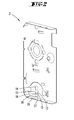
- a preferred embodiment of a door lock 1 is presented.
- This comprises two each formed from stampings housing 2, 3, which form a housing 4 in the assembled state.
- the housing wall 2 is a so-called lock cover and the housing wall 3 is a so-called lock floor.
- a narrow side of the lock housing 4 is formed by a cuff 5, through the upper window 6, a latch 7 and through the lower window 8, a bolt 9 are moved.
- a nut 10 mounted between the housing walls 2, 3 serves to displace the catch 7.
- An unshown nut arm of the nut 10 mounted in the lock housing engages a tail of the latch 7, not shown.
- the keyhole opening 13 has a round section 14 and a profile section 15, and the keyhole opening 13 'comprises a round section 14 'and a subsequent thereto profile section 15'.
- the profile section 15 is bounded by two side edges 16, 17, of which in the example closer to the cuff 5, straight continuous side edge 17 parallel to the cuff 5 and the side of the cuff 5 more distant side edge 16 between two to the cuff 5 parallel
- Edge sections a rounded starting from these edge portions in the keyhole opening 13 extending indentation 18, which is a formed during punching of the profile section with formed integrally formed on the housing wall 2 metal tongue.
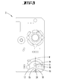
- M is an imaginary or geometric longitudinal opening center line, which runs parallel to the cuff 5 through the keyhole opening 13 through the center of the round portion 14 centrally between the straight portions of the side edges 16, 17, see. the top view from the outside in FIG. 3 , FIG.
- FIG. 5 shows its keyhole opening 13 ', which has a round portion 14' and a profile section 15 'has in this plan view the same shape as the keyhole 13 of the housing 2.
- an indentation 18 'having side edge 16' closer to the side adjacent to the cuff 5 housing side than the straight-running side edge 17 '.
- FIGS. 1 and 8th illustrate the two each have a recess 18, 18 'having side edges 16, 16' in a right angle through the two keyhole openings 13, 13 'guided projection view with respect to the opening longitudinal center lines M, M' of the keyhole openings 13, 13 'to each other axisymmetric ,
- FIG. 1 and 8th illustrate the two each have a recess 18, 18 'having side edges 16, 16' in a right angle through the two keyhole openings 13, 13 'guided projection view with respect to the opening longitudinal center lines M, M' of the keyhole openings 13, 13 'to each other axisymmetric ,
- FIG. 1 and 8th illustrate the two
- FIG. 1 illustrates the opening longitudinal center lines M, M 'in the said projection view, which are perpendicular to the plane of FIG. 1 through the keyhole 11 leads to each other congruent.
- the round sections 14, 14 ' are congruent to each other; The same applies in pairs for the four corners of the profile sections 15, 15 '.
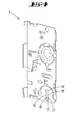
- FIG. 1 shown interior door lock 1 can be seen on the basis of the mounting position of his case 7 as so-called.
- Left lock ie as a lock for a room door, which is hinged in the direction of its opening side on the left side to the door frame.
- FIG. 1 This can be seen from the fact that the view of the inclined surface 19 of the case 7 falls. Deviating from this would be in a so-called right castle in the same position or viewing direction, the inclined surface 19 located on the back.
- FIG. 8 shows the vicinity of the keyhole 11 for the left lock according to FIG. 1 while compared to it
- FIG. 12 shows the vicinity of the keyhole 11 for a right-hand lock. From the comparison it is clear that the profile of the keyhole opening 13 of the left-hand lock with respect to the longitudinal opening center line M axis or mirror-symmetrical shaped to the profile of the keyhole opening 13 of the left-hand lock, which can be seen by the respective position of the indentation 18. This relationship applies analogously to the profiles of the keyhole openings 13 '.
- FIG. 6 its straw 20 is at the one longitudinal end in a ridge 21 on, and at the other longitudinal end of a beard 22 is formed laterally.
- FIG. 7 shows in a plan view of the beard profile whose key-to-key different form is referred to as a tail.
- This Buntbart achievel 12 is in the same direction in FIG. 9a shown.
- the FIGS. 9b to 9e show further, simplifying also designated 12 Buntbart administratl, each other and from the in FIG. 9a Buntbart achievel 12 shown differ by different tailings. Their commonality, according to the Buntbart achievel the FIGS.
- the in the FIGS. 13a to 13e shown, also simplifying with 12 designated Buntbart administratl form a second group in that their respective mutually different tailings, in spite of these differences in each case by definition, a right lock is assigned.
- the key to all of these keys is that in the FIGS. 13a-13e uniformly to the right side of the beard open indentation 23 of the bar 22.
- the Buntbart achievel 12 according to the FIGS. 9a to 9e form together with the Buntbart achieveln 12 according to the FIGS.
- the selected Buntbart wantl 12 has a hollow indentation 23 on his beard 22 and that in the projection view when inserting the Buntbart achievels 12 through the keyhole opening 13 formed on the profile section 15, formed by the housing recess 18 in this hollow recess 23 of the beard 22 fits without filling this hollow indentation 23 in cross-section.
- FIG. 11a shows that the indentation 18 'provided on the other keyhole opening 13' overlaps the beard 22 of the Buntbart achievel 12 in the projection view (the beard area lying behind the indentation 18 'formed of sheet metal is therefore shown in dashed lines) and in this way a stop for forms the beard 22, which prevents unintentional passage through the keyhole 11.
- FIGS. 9a to 9e show that as a group to that in the FIGS. 1 to 5 shown left matching key 12 on their beard 22 each have at least one hollow indentation 23, which, in spite of mutually different shape, in each case to a uniform within this group beard side, in the example in the direction towards the ridge to the left, is open.
- the indentations 18, 18 ' are selected on the keyhole 11 in terms of their position and shape so that they are in the insertion of each of the FIGS.
- FIG. 11d additionally shows by way of example that the extent b of the indentations 18, 18 'in the direction transverse to the longitudinal opening center line M is smaller than the width B of the respective profile section 15, 15'. This means that in the projection view of the FIGS. 11a to 11e between the apexes of the indentations 18 and 18 'in the direction transverse to the longitudinal opening center line M remains a gap.
- a rotational resistance 26 goes out. This is formed by an expression of the narrow side 27 and can slightly protrude into the contour frame of the two profile sections 15, 15 '.
- the Buntbartnachl 12 which fits into the keyholes 11 may have a beard 22 with a common tail.
- FIGS. 16 and 17 show the effect of the rotational resistance 26.
- the rotational resistance 26 protrudes partially into the circulation area of the beard 22, which forms the rotational resistance 26 expression forms a stop for a portion of the beard 22.
- the beard 22 in one of the two in the FIGS. 16 and 17 illustrated stop positions is at least a portion of the beard 22 outside both profile sections 15, 15 'and thus between the wall portions of the two housing walls 2, 3. This has the consequence that the key 12 can not fall out of the keyhole 11. Because of the movement play of the straw 20 in the round section 14, 14 ', the rotational resistance 26 can be overcome.
- Buntbartierel 12 has in the example, ie not necessary, between the ridge 21 and the beard 22 a radially projecting from the blade 20 stop projection 28. This is spaced slightly more than the material thickness of the housing walls 2, 3 from the beard 22. If such a key inserted into the keyhole 11, suggests the Stop projection 28 to the outside of the facing housing 2, 3 and forms an additional safety stop against unintentional passing through the Buntbart justifyls 12, so that formed on the opposite side of the keyhole 11 indentation 18 or 18 ', which is a Blechzunge acts, is relieved.
Landscapes
- Engineering & Computer Science (AREA)
- Mechanical Engineering (AREA)
- Securing Of Glass Panes Or The Like (AREA)
- Supports Or Holders For Household Use (AREA)
- Closures For Containers (AREA)
Applications Claiming Priority (1)
| Application Number | Priority Date | Filing Date | Title |
|---|---|---|---|
| DE202012102559U DE202012102559U1 (de) | 2012-07-11 | 2012-07-11 | Zimmertürschloss |
Publications (2)
| Publication Number | Publication Date |
|---|---|
| EP2685033A2 true EP2685033A2 (fr) | 2014-01-15 |
| EP2685033A3 EP2685033A3 (fr) | 2017-07-05 |
Family
ID=48793001
Family Applications (1)
| Application Number | Title | Priority Date | Filing Date |
|---|---|---|---|
| EP13175867.4A Withdrawn EP2685033A3 (fr) | 2012-07-11 | 2013-07-10 | Serrure de porte de chambre |
Country Status (2)
| Country | Link |
|---|---|
| EP (1) | EP2685033A3 (fr) |
| DE (1) | DE202012102559U1 (fr) |
Families Citing this family (1)
| Publication number | Priority date | Publication date | Assignee | Title |
|---|---|---|---|---|
| SE2350548A1 (en) * | 2023-05-05 | 2024-11-06 | Robust Ellaasning Ab | A main housing part of a lock housing, a lock housing and a method for manufacturing a housing part |
Citations (1)
| Publication number | Priority date | Publication date | Assignee | Title |
|---|---|---|---|---|
| DE202009001921U1 (de) | 2009-02-27 | 2010-07-22 | Schulte-Schlagbaum Aktiengesellschaft | Zimmertürschloss |
Family Cites Families (6)
| Publication number | Priority date | Publication date | Assignee | Title |
|---|---|---|---|---|
| DE25839C (de) * | — S. HlENDLMAYER in Eggenfelden, Niederbayern | Sicherheitsschlofs zu verschiedenartiger Sperrung mit mehreren Schlüsseln | ||
| DE208732C (fr) * | ||||
| DE689307C (de) * | 1938-01-01 | 1940-03-16 | Ludw Rocholl & Co | Tuerschloss |
| AT220505B (de) * | 1960-05-13 | 1962-03-26 | Zeiss Ikon Ag | Verschlußanlage mit durch Profilvariationen gruppierten Schlössern |
| CH506687A (de) * | 1970-08-18 | 1971-04-30 | Zeiss Ikon Ag | Zentralschlossanlage |
| DE4304604C2 (de) * | 1993-02-16 | 1999-06-02 | Heinz Wolter | Aus Schließzylindern und Schlüsseln bestehendes Schließanlagen-System |
-
2012
- 2012-07-11 DE DE202012102559U patent/DE202012102559U1/de not_active Expired - Lifetime
-
2013
- 2013-07-10 EP EP13175867.4A patent/EP2685033A3/fr not_active Withdrawn
Patent Citations (1)
| Publication number | Priority date | Publication date | Assignee | Title |
|---|---|---|---|---|
| DE202009001921U1 (de) | 2009-02-27 | 2010-07-22 | Schulte-Schlagbaum Aktiengesellschaft | Zimmertürschloss |
Also Published As
| Publication number | Publication date |
|---|---|
| DE202012102559U1 (de) | 2013-10-14 |
| EP2685033A3 (fr) | 2017-07-05 |
Similar Documents
| Publication | Publication Date | Title |
|---|---|---|
| DE20015566U1 (de) | Verriegelungsvorrichtung für eine Schublade | |
| EP2685030B1 (fr) | Cylindre de fermeture avec une clé correspondante | |
| AT409995B (de) | Schlüssel für zylinderschloss | |
| DE102004021580B3 (de) | Aus Schlüssel und Schließzylinder bestehende Schließvorrichtung | |
| EP0377135A2 (fr) | Clé pour serrure cylindrique | |
| DE102010012261B4 (de) | Schließsystem | |
| DE4108668B4 (de) | Schließzylinder-Schlüssel | |
| AT501706B1 (de) | Flachschlüssel sowie zugehöriges zylinderschloss | |
| EP2792822B1 (fr) | Codage via des poutres de blocage | |
| DE29614006U1 (de) | Verbindung zwischen Rolladenkasten und Fensterrahmen-Schenkel | |
| EP2685033A2 (fr) | Serrure de porte de chambre | |
| DE2135106C3 (de) | Schließvorrichtung mit Zylinderkern und Flachschlüssel | |
| EP2099989B1 (fr) | Crémone | |
| DE2461228C3 (de) | Verfahren zum Herstellen eines an eine jeweils vorgegebene Flügelhöhe angepaßten, einbaufertigen Fenster- oder Türverschlusses | |
| EP3521544A1 (fr) | Volet roulant pourvu d'arbre d'enroulement | |
| AT502746B1 (de) | Zylinderschloss sowie flachschlüssel | |
| DE3230312A1 (de) | Locher fuer papier- und pappwaren aus im wesentlichen zweistrangpress- bzw. extrusionsprofilen | |
| DE102008051356B4 (de) | Trennwandsystem | |
| DE3512856A1 (de) | Verbesserungen an abgeschirmten und/oder gepanzerten tueren | |
| DE10122368B4 (de) | Schloss | |
| DE202015100746U1 (de) | Betonfertigteil | |
| DE202009001921U1 (de) | Zimmertürschloss | |
| DE29722567U1 (de) | Stiftzylinderschloß | |
| DE102007041964B3 (de) | Schloss-Schlüsselkombination | |
| AT521400B1 (de) | Vorsatztür, insbesondere Insektenschutztür |
Legal Events
| Date | Code | Title | Description |
|---|---|---|---|
| PUAI | Public reference made under article 153(3) epc to a published international application that has entered the european phase |
Free format text: ORIGINAL CODE: 0009012 |
|
| AK | Designated contracting states |
Kind code of ref document: A2 Designated state(s): AL AT BE BG CH CY CZ DE DK EE ES FI FR GB GR HR HU IE IS IT LI LT LU LV MC MK MT NL NO PL PT RO RS SE SI SK SM TR |
|
| AX | Request for extension of the european patent |
Extension state: BA ME |
|
| PUAL | Search report despatched |
Free format text: ORIGINAL CODE: 0009013 |
|
| AK | Designated contracting states |
Kind code of ref document: A3 Designated state(s): AL AT BE BG CH CY CZ DE DK EE ES FI FR GB GR HR HU IE IS IT LI LT LU LV MC MK MT NL NO PL PT RO RS SE SI SK SM TR |
|
| AX | Request for extension of the european patent |
Extension state: BA ME |
|
| RIC1 | Information provided on ipc code assigned before grant |
Ipc: E05B 15/16 20060101ALI20170529BHEP Ipc: E05B 9/02 20060101ALI20170529BHEP Ipc: E05B 63/04 20060101ALI20170529BHEP Ipc: E05B 19/06 20060101ALI20170529BHEP Ipc: E05B 19/00 20060101ALI20170529BHEP Ipc: E05B 63/08 20060101AFI20170529BHEP |
|
| 17P | Request for examination filed |
Effective date: 20171221 |
|
| RBV | Designated contracting states (corrected) |
Designated state(s): AL AT BE BG CH CY CZ DE DK EE ES FI FR GB GR HR HU IE IS IT LI LT LU LV MC MK MT NL NO PL PT RO RS SE SI SK SM TR |
|
| 17Q | First examination report despatched |
Effective date: 20181114 |
|
| STAA | Information on the status of an ep patent application or granted ep patent |
Free format text: STATUS: THE APPLICATION HAS BEEN WITHDRAWN |
|
| 18W | Application withdrawn |
Effective date: 20190116 |