EP2685159A1 - Brûleur à gaz portatif et procédé de montage - Google Patents
Brûleur à gaz portatif et procédé de montage Download PDFInfo
- Publication number
- EP2685159A1 EP2685159A1 EP13176049.8A EP13176049A EP2685159A1 EP 2685159 A1 EP2685159 A1 EP 2685159A1 EP 13176049 A EP13176049 A EP 13176049A EP 2685159 A1 EP2685159 A1 EP 2685159A1
- Authority
- EP
- European Patent Office
- Prior art keywords
- supply tube
- support structure
- wall
- combustion chamber
- spreader member
- Prior art date
- Legal status (The legal status is an assumption and is not a legal conclusion. Google has not performed a legal analysis and makes no representation as to the accuracy of the status listed.)
- Granted
Links
Images





Classifications
-
- F—MECHANICAL ENGINEERING; LIGHTING; HEATING; WEAPONS; BLASTING
- F23—COMBUSTION APPARATUS; COMBUSTION PROCESSES
- F23C—METHODS OR APPARATUS FOR COMBUSTION USING FLUID FUEL OR SOLID FUEL SUSPENDED IN A CARRIER GAS OR AIR
- F23C3/00—Combustion apparatus characterised by the shape of the combustion chamber
- F23C3/002—Combustion apparatus characterised by the shape of the combustion chamber the chamber having an elongated tubular form, e.g. for a radiant tube
-
- F—MECHANICAL ENGINEERING; LIGHTING; HEATING; WEAPONS; BLASTING
- F23—COMBUSTION APPARATUS; COMBUSTION PROCESSES
- F23D—BURNERS
- F23D14/00—Burners for combustion of a gas, e.g. of a gas stored under pressure as a liquid
- F23D14/46—Details
- F23D14/62—Mixing devices; Mixing tubes
- F23D14/64—Mixing devices; Mixing tubes with injectors
-
- F—MECHANICAL ENGINEERING; LIGHTING; HEATING; WEAPONS; BLASTING
- F23—COMBUSTION APPARATUS; COMBUSTION PROCESSES
- F23C—METHODS OR APPARATUS FOR COMBUSTION USING FLUID FUEL OR SOLID FUEL SUSPENDED IN A CARRIER GAS OR AIR
- F23C2900/00—Special features of, or arrangements for combustion apparatus using fluid fuels or solid fuels suspended in air; Combustion processes therefor
- F23C2900/03009—Elongated tube-shaped combustion chambers
Definitions
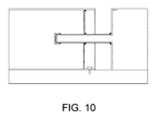
- a portable gas heater in particular a liquefied propane gas (LPG), of the type represented in Figure 10 .
- LPG liquefied propane gas
- Fig. 10 illustrates a portable gas heater of the prior art, in which the single components are connected together by weldings.
- the known portable heaters while being reliable and structurally resistant, have some drawbacks.
- the assembling requires long times and skilled labour, and the replacement of single worn or damaged components is very difficult.
- the weldings due to the different thermal dilations of the single components, the weldings have to be over-dimensioned in order to resist the thermal tensions that occur during the operation of the heater.
- the object of the present invention is to provide a portable gas heater of the type described above, as well as a manufacturing procedure of such a portable gas heater, having characteristics such as to at least in part obviate the drawbacks mentioned with reference to the prior art.
- a particular object of the invention is to provide a portable gas burner having characteristics such as to simplify and make the assembling quicker without the need for skilled labour.
- a further object of the invention is to provide a portable gas burner having characteristics such as to facilitate the replacement of single worn or damaged components.
- a portable gas heater comprising:
- a portable gas heater comprising:
- the object of the invention is further achieved by a method for assembling a portable gas heater comprising:
- a method for assembling a portable gas heater comprising:
- Fig. 1 is a perspective view of a portable gas heater according to an embodiment, in which a part of the housing was removed;
- Fig. 2 illustrates the heater in Fig. 1 with an outer housing completely removed
- Fig. 3 is a perspective view of a detail of the heater in Fig. 1 ;
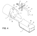
- Fig. 4 is an exploded view of the heater in Fig. 1 ;
- Fig. 5 is an enlarged view of some details in Fig. 4 ;
- Fig. 6 shows a series of enlarged views of details of the heater according to an embodiment
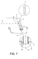
- Fig. 7 shows a side view (with a partially removed housing) of a burner according to an embodiment, and two enlarged views of details of the heater;
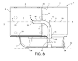
- Fig. 8 is a longitudinal sectional view of a portable heater according to an embodiment
- Fig. 9 is a schematized representation of the constraints carried out during the assembling of a portable heater according to an embodiment
- Fig. 10 shows a gas heater according to the prior art.
- a portable gas heater 1 comprises a support structure 2 having a front side 3 and a rear side 4 opposite the front side 3.
- the support structure 2 may comprise one or more resting feet 24 defining a resting plane 25 and a normal use position of the heater 1.
- the portable heater 1 further comprises:
- tubular side wall 5 connected to the support structure 2 and having a longitudinal axis 6, the tubular wall 5 defining internally a combustion chamber 7 and having a front end 8 facing the front side 3 and open to allow the outflow of hot combusted gases from the combustion chamber 7, as well as a rear end 9 facing the rear side 4,
- a protection grid 10 connected to the front end 8 of the side wall 5 and a outer housing 11,
- a supply tube 13 for supplying fuel gas to the combustion chamber 7, said supply tube 13 having a front length 14 extending through the rear wall 12 to the inside of the combustion chamber 7 and a rear length 15 extending outside of the combustion chamber,
- a flame spreader member 16 connected to an outlet port 17 of the front length 14 of the supply tube 13 and shaped to prevent a reverse flow of flame in the tube 13.
- the side wall 5 is locked to the support structure 2 so as to prevent a translation of the side wall 5, with respect to the support structure 2, parallel to the longitudinal axis 6, and
- the rear length 15 of the supply tube 13 is inserted in a tube seat 18 of the support structure 2 along a first connection axis 19 transversal to the longitudinal axis 6 so as to prevent a translation of the supply tube 13, with respect to the support structure 2, parallel to the longitudinal axis 6 and a rotation of the supply tube 13, with respect to the support structure 2, around an axis parallel to the longitudinal axis 6, and
- the flame spreader member 16 is inserted from the front side 3 on the front length 14 of the supply tube 13 along a second connection axis 20 transversal to the first connection axis 19 and parallel to the longitudinal axis 6, and
- the front length 14 of the supply tube 13 and the flame spreader member 16 are both inserted along the second connection axis 20 in a passage opening 21 of the rear wall 12, and
- the front length 14 of the supply tube 13 abuts from the rear side 4 against an abutment surface 22 of the flame spreader member 16 so as to prevent a further translation of the flame spreader member 16 with respect to the supply tube 13 towards the rear side 4, and
- the rear wall 12 abuts from the front side 3 against a stop surface 23 of the flame spreader member 16 so as to prevent a further translation of the rear wall 12 towards the rear side 4.
- a method for assembling the heater 1 comprises the step or steps of carrying out at least one of the connections:
- a method for assembling the heater 1 comprises the steps of:
- the rear wall 12 abuts from the rear side 4 against one or more projections 26 of the flame spreader member 16 so as to lock the rear wall 12 between the stop surface 23 and the projection 26 and to prevent a translation thereof with respect to the flame spreader member 16 in both directions along the second connection axis 20.
- the rear wall 12 is inserted in the rear end 9 of the side wall 5 and abuts from the rear side 4 against a stop surface 27 of the side wall 5 so as to prevent a further translation of the rear wall 12 with respect to the side wall 5 towards the front side 3.
- the rear wall 12 is connected to the side wall 5 by a geometrical coupling preventing a relative rotation thereof around an axis parallel to the longitudinal axis 6.
- the side wall 5 comprises a rigid metal sheet (e.g., in steel) substantially cylindrical or frusto-conical, developing concentrically around the longitudinal axis 6.
- a rear edge 9 of the side wall forms one or more, preferably four, (preferably trapezoidal) grooves 28 or cavities open towards the rear side 4 and suitable to receive coupling portions 29 of the rear wall 12.
- the grooves 28 or cavities are preferably formed in diametrically opposite positions, or with a constant angular pitch along the perimeter of the side wall 12.
- the rear wall 12 may comprise a rigid metal sheet (in steel) in the shape of a circular disc having an outer diameter less than an inner diameter of the rear end 9 of the side wall 5.
- the disc-shaped sheet defines the above-mentioned passage opening 21 receiving the supply tube 13 and the flame spreader member 16.
- the rear wall 12 may further comprise a plurality of suction openings for suctioning oxidizing air into the combustion chamber 7.
- the rear wall 12 comprises a reinforcing and coupling frame 30 that may be formed in a single piece with the disc-shaped metal sheet, for example, by press forming, or manufactured separately and subsequently connected thereto.
- the frame 30 forms a reinforcing ring around the passage opening and a plurality of (preferably four) ribs extending from the reinforcing ring radially outwardly and having free ends projecting beyond the outer perimeter of the disc-shaped sheet and form the coupling portions 29.
- the width of the coupling portions 29 may be less than or equal to the width of the bottom (stop surface 27) of the grooves 28 or cavities (for example, of the lesser base in the case of trapezoidal grooves) of the side wall 5, so as to ensure an anti-rotation coupling with reduced clearances.
- the rear wall 12, preferably the reinforcing ring of the frame 30, forms a slit 31 near the passage opening 21 and an enlargement screw 32 having a diameter larger than the minimum width of the slit 31 is screwed therein to deform the edge of the passage opening 21 radially inwardly and thereby creating an interference coupling between the rear wall 12 and the supply tube 13.
- Such interference coupling is particularly useful to ensure a proper mutual positioning of the two components in the assembling step.
- the side wall 5 may be locked to the support structure 2 by a screw connection ( Figure 2 , screw 33) or, alternatively, by a shape connection.
- the insertion of the rear length 15 of the supply tube 13 into the tube seat 18 of the support structure 2 preferably implement an interference fit and, still more preferably, free from additional weldings or connection members (e. g., screws).
- first connection axis 19 substantially perpendicular to the longitudinal axis 6 of the side wall 5, for example, such first connection axis 19 may be perpendicular with respect to the resting plane 25 of the support structure 2.
- the tube seat 18 comprises a tubular portion substantially rectilinear and oriented according to such first connection axis 19.
- the tube seat 18 may have an inner shape substantially complementary to the outer shape of a free end (inlet end) of the rear length 15 of the supply tube 13, so as to allow the insertion with interference of the latter.
- the tube seat 18 may further form an abutment shoulder 42 forming a sure reference for the positioning (insertion depth) of the supply tube 13 in the tube seat 18.
- the insertion of the flame spreader member 16 on the front length 14 of the supply tube 13 also implements a clearance fit and, preferably, free from additional weldings or connection members (e.g., screws).
- the second connection axis 20 is concentric with the longitudinal axis 6, for example, such second connection axis 20 may be substantially parallel with respect to the resting plane 25 and horizontal when the heater 1 is in the use position.
- the flame spreader member 16 comprises a front plate 34 facing the front side 3 and a plurality of rear wings 35 extending from the front plate 34 towards the rear side 4 and defining a rear seat receiving, by fitting, the outlet port 17 of the supply tube 13.
- the rear wings 35 may elastically deflect outwardly to exert an elastic force onto the supply tube 13 such as to elastically hold it into the rear seat.
- the outlet port 17 of the supply tube 13 and the rear seat of the flame spreader member 16 are aligned and oriented according to the second connection axis 20.
- the same rear wings 35 may form a shoulder, for example, a step, which forms the above-mentioned abutment surface 22 against which the free edge of the outlet port 17 of the supply tube 13 abuts.
- the flame spreader member 16 may further form one or more, preferably two, stop wings 36 extending from the front plate 34 towards the rear side 4 and possibly having a length larger than the length of the rear wings 35.
- the free ends of the stop wings 36 are bent radially outwardly (with respect to the rear seat of the flame spreader member and the second connection axis) and form the above-mentioned stop surface 23 against which the rear wall 12 abuts.
- the stop wings 36 may elastically deflect in a direction radial to the second connection axis 20 and exert an elastic pre-load (in a radially outer direction) on the rear wall 12 to elastically hold it in place.
- the stop wings 36 form, near the bent free ends, one or more (preferably two) projections 26 extending in a direction transversal to the second connection axis 20 and, possibly, transversal to the extension direction of the bent free ends.
- projections 26 are suitable to abut from the front side 3 against the rear wall 12 so that the rear wall 12 is locked between the projections 26 and the bent ends, without no possibility to translate with respect to the flame spreader member 16 along the second connection axis 20.
- the supply tube 13 is a rigid metal tube (for example, in steel) the front 14 and rear 15 lengths thereof define therebetween an angle of preferably 90°.
- the heater 1 may further comprise a control unit 37 for adjusting the supply of fuel gas to the supply tube.
- control unit 37 includes an adjustment conduit 38 with an inlet opening 39 connectable to a fuel gas source and an outlet opening 40 in communication with the outer length 15 of the supply tube 13, as well as valve means 41 arranged in the adjustment conduit 38 and suitable to adjust the flow rate of the flow in said adjustment conduit 38.
Landscapes
- Engineering & Computer Science (AREA)
- Chemical & Material Sciences (AREA)
- Combustion & Propulsion (AREA)
- Mechanical Engineering (AREA)
- General Engineering & Computer Science (AREA)
- Gas Burners (AREA)
- Combustion Of Fluid Fuel (AREA)
Applications Claiming Priority (1)
| Application Number | Priority Date | Filing Date | Title |
|---|---|---|---|
| IT001215A ITMI20121215A1 (it) | 2012-07-12 | 2012-07-12 | Bruciatore a gas portatile e metodo di assemblaggio |
Publications (2)
| Publication Number | Publication Date |
|---|---|
| EP2685159A1 true EP2685159A1 (fr) | 2014-01-15 |
| EP2685159B1 EP2685159B1 (fr) | 2018-01-10 |
Family
ID=46800264
Family Applications (1)
| Application Number | Title | Priority Date | Filing Date |
|---|---|---|---|
| EP13176049.8A Not-in-force EP2685159B1 (fr) | 2012-07-12 | 2013-07-11 | Brûleur à gaz portatif et procédé de montage |
Country Status (2)
| Country | Link |
|---|---|
| EP (1) | EP2685159B1 (fr) |
| IT (1) | ITMI20121215A1 (fr) |
Citations (3)
| Publication number | Priority date | Publication date | Assignee | Title |
|---|---|---|---|---|
| US2815019A (en) * | 1955-12-29 | 1957-12-03 | Edward A Keible | Portable hydrocarbon burner |
| DE19927013A1 (de) * | 1999-06-07 | 2000-12-14 | Vaillant Joh Gmbh & Co | Gebläsebrenner |
| US7566218B2 (en) * | 2004-09-14 | 2009-07-28 | Acl Manufacturing Inc. | Burner assembly |
-
2012
- 2012-07-12 IT IT001215A patent/ITMI20121215A1/it unknown
-
2013
- 2013-07-11 EP EP13176049.8A patent/EP2685159B1/fr not_active Not-in-force
Patent Citations (3)
| Publication number | Priority date | Publication date | Assignee | Title |
|---|---|---|---|---|
| US2815019A (en) * | 1955-12-29 | 1957-12-03 | Edward A Keible | Portable hydrocarbon burner |
| DE19927013A1 (de) * | 1999-06-07 | 2000-12-14 | Vaillant Joh Gmbh & Co | Gebläsebrenner |
| US7566218B2 (en) * | 2004-09-14 | 2009-07-28 | Acl Manufacturing Inc. | Burner assembly |
Also Published As
| Publication number | Publication date |
|---|---|
| ITMI20121215A1 (it) | 2014-01-13 |
| EP2685159B1 (fr) | 2018-01-10 |
Similar Documents
| Publication | Publication Date | Title |
|---|---|---|
| JP6529364B2 (ja) | 給湯器 | |
| US20150167964A1 (en) | Adjustable Vortex Flame Device | |
| CN106796034A (zh) | 联焰导管 | |
| CN101512205B (zh) | 燃烧器管的卡口连接 | |
| US20190017701A1 (en) | Piping connection unit, air supply or exhaust tube, and combustion apparatus | |
| EP2685159B1 (fr) | Brûleur à gaz portatif et procédé de montage | |
| EP2886954A1 (fr) | Dispositif de flamme tourbillonnaire réglable pour une lampe à combustible liquide | |
| CN107208895B (zh) | 用于燃气轮机燃烧室的具有快速卡扣配合燃料进给接合部的燃料供给系统 | |
| JP6616689B2 (ja) | コンロ | |
| US11002445B2 (en) | Gas burner for boiler | |
| EP2083217B1 (fr) | Brûleur à gaz pour une chaudière | |
| CN109764359B (zh) | 燃烧室头部装配结构、燃烧室及航空发动机 | |
| JP2006052758A (ja) | ガス栓 | |
| AU2006212431B2 (en) | A quick attach and safe release arrangement for a port of a water pump | |
| US11473779B2 (en) | Gas valve for a cooktop appliance | |
| JP5691423B2 (ja) | 大気吸込み弁装置 | |
| CN221975247U (zh) | 分火器和燃烧器 | |
| EP3299720B1 (fr) | Ensemble avant de chambre de combustion pour turbine à gaz | |
| CN104235842A (zh) | 用于家用电器的双引燃燃烧器 | |
| CN110686278A (zh) | 输气装置及燃气灶 | |
| US20230374719A1 (en) | Modular laundry dryer burner assembly | |
| KR20170107395A (ko) | 예혼합 열교환셀용 다기능 슬리브와, 다기능 슬리브와 지지부 조립체, 및 예혼합 열교환셀 | |
| JPH1114013A (ja) | ガスバーナ |
Legal Events
| Date | Code | Title | Description |
|---|---|---|---|
| PUAI | Public reference made under article 153(3) epc to a published international application that has entered the european phase |
Free format text: ORIGINAL CODE: 0009012 |
|
| AK | Designated contracting states |
Kind code of ref document: A1 Designated state(s): AL AT BE BG CH CY CZ DE DK EE ES FI FR GB GR HR HU IE IS IT LI LT LU LV MC MK MT NL NO PL PT RO RS SE SI SK SM TR |
|
| AX | Request for extension of the european patent |
Extension state: BA ME |
|
| 17P | Request for examination filed |
Effective date: 20140709 |
|
| RBV | Designated contracting states (corrected) |
Designated state(s): AL AT BE BG CH CY CZ DE DK EE ES FI FR GB GR HR HU IE IS IT LI LT LU LV MC MK MT NL NO PL PT RO RS SE SI SK SM TR |
|
| RAP1 | Party data changed (applicant data changed or rights of an application transferred) |
Owner name: MCS ITALY S.P.A. |
|
| RIN1 | Information on inventor provided before grant (corrected) |
Inventor name: CECCHINI, MARCO Inventor name: GIARETTA, ENZO |
|
| RIC1 | Information provided on ipc code assigned before grant |
Ipc: F23C 3/00 20060101AFI20170606BHEP Ipc: F23D 14/64 20060101ALI20170606BHEP |
|
| GRAP | Despatch of communication of intention to grant a patent |
Free format text: ORIGINAL CODE: EPIDOSNIGR1 |
|
| INTG | Intention to grant announced |
Effective date: 20170718 |
|
| GRAS | Grant fee paid |
Free format text: ORIGINAL CODE: EPIDOSNIGR3 |
|
| GRAA | (expected) grant |
Free format text: ORIGINAL CODE: 0009210 |
|
| AK | Designated contracting states |
Kind code of ref document: B1 Designated state(s): AL AT BE BG CH CY CZ DE DK EE ES FI FR GB GR HR HU IE IS IT LI LT LU LV MC MK MT NL NO PL PT RO RS SE SI SK SM TR |
|
| REG | Reference to a national code |
Ref country code: CH Ref legal event code: EP Ref country code: AT Ref legal event code: REF Ref document number: 962801 Country of ref document: AT Kind code of ref document: T Effective date: 20180115 |
|
| REG | Reference to a national code |
Ref country code: IE Ref legal event code: FG4D |
|
| REG | Reference to a national code |
Ref country code: DE Ref legal event code: R096 Ref document number: 602013031875 Country of ref document: DE |
|
| REG | Reference to a national code |
Ref country code: NL Ref legal event code: MP Effective date: 20180110 |
|
| REG | Reference to a national code |
Ref country code: AT Ref legal event code: MK05 Ref document number: 962801 Country of ref document: AT Kind code of ref document: T Effective date: 20180110 |
|
| REG | Reference to a national code |
Ref country code: DE Ref legal event code: R081 Ref document number: 602013031875 Country of ref document: DE Owner name: DANTHERM S.P.A., IT Free format text: FORMER OWNER: MCS ITALY S.P.A., PASTRENGO, VERONA, IT |
|
| PG25 | Lapsed in a contracting state [announced via postgrant information from national office to epo] |
Ref country code: NL Free format text: LAPSE BECAUSE OF FAILURE TO SUBMIT A TRANSLATION OF THE DESCRIPTION OR TO PAY THE FEE WITHIN THE PRESCRIBED TIME-LIMIT Effective date: 20180110 |
|
| RAP2 | Party data changed (patent owner data changed or rights of a patent transferred) |
Owner name: DANTHERM S.P.A. |
|
| PG25 | Lapsed in a contracting state [announced via postgrant information from national office to epo] |
Ref country code: NO Free format text: LAPSE BECAUSE OF FAILURE TO SUBMIT A TRANSLATION OF THE DESCRIPTION OR TO PAY THE FEE WITHIN THE PRESCRIBED TIME-LIMIT Effective date: 20180410 Ref country code: FI Free format text: LAPSE BECAUSE OF FAILURE TO SUBMIT A TRANSLATION OF THE DESCRIPTION OR TO PAY THE FEE WITHIN THE PRESCRIBED TIME-LIMIT Effective date: 20180110 Ref country code: ES Free format text: LAPSE BECAUSE OF FAILURE TO SUBMIT A TRANSLATION OF THE DESCRIPTION OR TO PAY THE FEE WITHIN THE PRESCRIBED TIME-LIMIT Effective date: 20180110 Ref country code: HR Free format text: LAPSE BECAUSE OF FAILURE TO SUBMIT A TRANSLATION OF THE DESCRIPTION OR TO PAY THE FEE WITHIN THE PRESCRIBED TIME-LIMIT Effective date: 20180110 Ref country code: CY Free format text: LAPSE BECAUSE OF FAILURE TO SUBMIT A TRANSLATION OF THE DESCRIPTION OR TO PAY THE FEE WITHIN THE PRESCRIBED TIME-LIMIT Effective date: 20180110 Ref country code: LT Free format text: LAPSE BECAUSE OF FAILURE TO SUBMIT A TRANSLATION OF THE DESCRIPTION OR TO PAY THE FEE WITHIN THE PRESCRIBED TIME-LIMIT Effective date: 20180110 |
|
| PG25 | Lapsed in a contracting state [announced via postgrant information from national office to epo] |
Ref country code: GR Free format text: LAPSE BECAUSE OF FAILURE TO SUBMIT A TRANSLATION OF THE DESCRIPTION OR TO PAY THE FEE WITHIN THE PRESCRIBED TIME-LIMIT Effective date: 20180411 Ref country code: BG Free format text: LAPSE BECAUSE OF FAILURE TO SUBMIT A TRANSLATION OF THE DESCRIPTION OR TO PAY THE FEE WITHIN THE PRESCRIBED TIME-LIMIT Effective date: 20180410 Ref country code: PL Free format text: LAPSE BECAUSE OF FAILURE TO SUBMIT A TRANSLATION OF THE DESCRIPTION OR TO PAY THE FEE WITHIN THE PRESCRIBED TIME-LIMIT Effective date: 20180110 Ref country code: IS Free format text: LAPSE BECAUSE OF FAILURE TO SUBMIT A TRANSLATION OF THE DESCRIPTION OR TO PAY THE FEE WITHIN THE PRESCRIBED TIME-LIMIT Effective date: 20180510 Ref country code: RS Free format text: LAPSE BECAUSE OF FAILURE TO SUBMIT A TRANSLATION OF THE DESCRIPTION OR TO PAY THE FEE WITHIN THE PRESCRIBED TIME-LIMIT Effective date: 20180110 Ref country code: LV Free format text: LAPSE BECAUSE OF FAILURE TO SUBMIT A TRANSLATION OF THE DESCRIPTION OR TO PAY THE FEE WITHIN THE PRESCRIBED TIME-LIMIT Effective date: 20180110 Ref country code: SE Free format text: LAPSE BECAUSE OF FAILURE TO SUBMIT A TRANSLATION OF THE DESCRIPTION OR TO PAY THE FEE WITHIN THE PRESCRIBED TIME-LIMIT Effective date: 20180110 Ref country code: AT Free format text: LAPSE BECAUSE OF FAILURE TO SUBMIT A TRANSLATION OF THE DESCRIPTION OR TO PAY THE FEE WITHIN THE PRESCRIBED TIME-LIMIT Effective date: 20180110 |
|
| REG | Reference to a national code |
Ref country code: DE Ref legal event code: R097 Ref document number: 602013031875 Country of ref document: DE |
|
| PG25 | Lapsed in a contracting state [announced via postgrant information from national office to epo] |
Ref country code: EE Free format text: LAPSE BECAUSE OF FAILURE TO SUBMIT A TRANSLATION OF THE DESCRIPTION OR TO PAY THE FEE WITHIN THE PRESCRIBED TIME-LIMIT Effective date: 20180110 Ref country code: RO Free format text: LAPSE BECAUSE OF FAILURE TO SUBMIT A TRANSLATION OF THE DESCRIPTION OR TO PAY THE FEE WITHIN THE PRESCRIBED TIME-LIMIT Effective date: 20180110 Ref country code: AL Free format text: LAPSE BECAUSE OF FAILURE TO SUBMIT A TRANSLATION OF THE DESCRIPTION OR TO PAY THE FEE WITHIN THE PRESCRIBED TIME-LIMIT Effective date: 20180110 |
|
| PLBE | No opposition filed within time limit |
Free format text: ORIGINAL CODE: 0009261 |
|
| STAA | Information on the status of an ep patent application or granted ep patent |
Free format text: STATUS: NO OPPOSITION FILED WITHIN TIME LIMIT |
|
| PG25 | Lapsed in a contracting state [announced via postgrant information from national office to epo] |
Ref country code: CZ Free format text: LAPSE BECAUSE OF FAILURE TO SUBMIT A TRANSLATION OF THE DESCRIPTION OR TO PAY THE FEE WITHIN THE PRESCRIBED TIME-LIMIT Effective date: 20180110 Ref country code: SK Free format text: LAPSE BECAUSE OF FAILURE TO SUBMIT A TRANSLATION OF THE DESCRIPTION OR TO PAY THE FEE WITHIN THE PRESCRIBED TIME-LIMIT Effective date: 20180110 Ref country code: DK Free format text: LAPSE BECAUSE OF FAILURE TO SUBMIT A TRANSLATION OF THE DESCRIPTION OR TO PAY THE FEE WITHIN THE PRESCRIBED TIME-LIMIT Effective date: 20180110 Ref country code: SM Free format text: LAPSE BECAUSE OF FAILURE TO SUBMIT A TRANSLATION OF THE DESCRIPTION OR TO PAY THE FEE WITHIN THE PRESCRIBED TIME-LIMIT Effective date: 20180110 |
|
| 26N | No opposition filed |
Effective date: 20181011 |
|
| PGFP | Annual fee paid to national office [announced via postgrant information from national office to epo] |
Ref country code: DE Payment date: 20180928 Year of fee payment: 6 |
|
| PG25 | Lapsed in a contracting state [announced via postgrant information from national office to epo] |
Ref country code: SI Free format text: LAPSE BECAUSE OF FAILURE TO SUBMIT A TRANSLATION OF THE DESCRIPTION OR TO PAY THE FEE WITHIN THE PRESCRIBED TIME-LIMIT Effective date: 20180110 |
|
| REG | Reference to a national code |
Ref country code: CH Ref legal event code: PL |
|
| GBPC | Gb: european patent ceased through non-payment of renewal fee |
Effective date: 20180711 |
|
| PG25 | Lapsed in a contracting state [announced via postgrant information from national office to epo] |
Ref country code: LU Free format text: LAPSE BECAUSE OF NON-PAYMENT OF DUE FEES Effective date: 20180711 Ref country code: MC Free format text: LAPSE BECAUSE OF FAILURE TO SUBMIT A TRANSLATION OF THE DESCRIPTION OR TO PAY THE FEE WITHIN THE PRESCRIBED TIME-LIMIT Effective date: 20180110 |
|
| REG | Reference to a national code |
Ref country code: BE Ref legal event code: MM Effective date: 20180731 |
|
| REG | Reference to a national code |
Ref country code: IE Ref legal event code: MM4A |
|
| PG25 | Lapsed in a contracting state [announced via postgrant information from national office to epo] |
Ref country code: FR Free format text: LAPSE BECAUSE OF NON-PAYMENT OF DUE FEES Effective date: 20180731 Ref country code: CH Free format text: LAPSE BECAUSE OF NON-PAYMENT OF DUE FEES Effective date: 20180731 Ref country code: LI Free format text: LAPSE BECAUSE OF NON-PAYMENT OF DUE FEES Effective date: 20180731 Ref country code: GB Free format text: LAPSE BECAUSE OF NON-PAYMENT OF DUE FEES Effective date: 20180711 Ref country code: IE Free format text: LAPSE BECAUSE OF NON-PAYMENT OF DUE FEES Effective date: 20180711 |
|
| PG25 | Lapsed in a contracting state [announced via postgrant information from national office to epo] |
Ref country code: BE Free format text: LAPSE BECAUSE OF NON-PAYMENT OF DUE FEES Effective date: 20180731 |
|
| PG25 | Lapsed in a contracting state [announced via postgrant information from national office to epo] |
Ref country code: IT Free format text: LAPSE BECAUSE OF NON-PAYMENT OF DUE FEES Effective date: 20180711 |
|
| PG25 | Lapsed in a contracting state [announced via postgrant information from national office to epo] |
Ref country code: MT Free format text: LAPSE BECAUSE OF NON-PAYMENT OF DUE FEES Effective date: 20180711 |
|
| REG | Reference to a national code |
Ref country code: DE Ref legal event code: R119 Ref document number: 602013031875 Country of ref document: DE |
|
| PG25 | Lapsed in a contracting state [announced via postgrant information from national office to epo] |
Ref country code: TR Free format text: LAPSE BECAUSE OF FAILURE TO SUBMIT A TRANSLATION OF THE DESCRIPTION OR TO PAY THE FEE WITHIN THE PRESCRIBED TIME-LIMIT Effective date: 20180110 |
|
| PG25 | Lapsed in a contracting state [announced via postgrant information from national office to epo] |
Ref country code: DE Free format text: LAPSE BECAUSE OF NON-PAYMENT OF DUE FEES Effective date: 20200201 |
|
| PG25 | Lapsed in a contracting state [announced via postgrant information from national office to epo] |
Ref country code: HU Free format text: LAPSE BECAUSE OF FAILURE TO SUBMIT A TRANSLATION OF THE DESCRIPTION OR TO PAY THE FEE WITHIN THE PRESCRIBED TIME-LIMIT; INVALID AB INITIO Effective date: 20130711 Ref country code: PT Free format text: LAPSE BECAUSE OF FAILURE TO SUBMIT A TRANSLATION OF THE DESCRIPTION OR TO PAY THE FEE WITHIN THE PRESCRIBED TIME-LIMIT Effective date: 20180110 |
|
| PG25 | Lapsed in a contracting state [announced via postgrant information from national office to epo] |
Ref country code: MK Free format text: LAPSE BECAUSE OF NON-PAYMENT OF DUE FEES Effective date: 20180110 |