EP2685255A2 - Wandlermodul mit gebogenem Oberflächenrahmen, Ultraschallsonde mit dem Wandlermodul und Verfahren zum Herstellen des gebogenen Oberflächenrahmens - Google Patents
Wandlermodul mit gebogenem Oberflächenrahmen, Ultraschallsonde mit dem Wandlermodul und Verfahren zum Herstellen des gebogenen Oberflächenrahmens Download PDFInfo
- Publication number
- EP2685255A2 EP2685255A2 EP13175789.0A EP13175789A EP2685255A2 EP 2685255 A2 EP2685255 A2 EP 2685255A2 EP 13175789 A EP13175789 A EP 13175789A EP 2685255 A2 EP2685255 A2 EP 2685255A2
- Authority
- EP
- European Patent Office
- Prior art keywords
- surface frame
- curved surface
- transducer
- master mold
- curved
- Prior art date
- Legal status (The legal status is an assumption and is not a legal conclusion. Google has not performed a legal analysis and makes no representation as to the accuracy of the status listed.)
- Withdrawn
Links
Images








Classifications
-
- B—PERFORMING OPERATIONS; TRANSPORTING
- B06—GENERATING OR TRANSMITTING MECHANICAL VIBRATIONS IN GENERAL
- B06B—METHODS OR APPARATUS FOR GENERATING OR TRANSMITTING MECHANICAL VIBRATIONS OF INFRASONIC, SONIC, OR ULTRASONIC FREQUENCY, e.g. FOR PERFORMING MECHANICAL WORK IN GENERAL
- B06B1/00—Methods or apparatus for generating mechanical vibrations of infrasonic, sonic, or ultrasonic frequency
- B06B1/02—Methods or apparatus for generating mechanical vibrations of infrasonic, sonic, or ultrasonic frequency making use of electrical energy
- B06B1/06—Methods or apparatus for generating mechanical vibrations of infrasonic, sonic, or ultrasonic frequency making use of electrical energy operating with piezoelectric effect or with electrostriction
- B06B1/0607—Methods or apparatus for generating mechanical vibrations of infrasonic, sonic, or ultrasonic frequency making use of electrical energy operating with piezoelectric effect or with electrostriction using multiple elements
- B06B1/0622—Methods or apparatus for generating mechanical vibrations of infrasonic, sonic, or ultrasonic frequency making use of electrical energy operating with piezoelectric effect or with electrostriction using multiple elements on one surface
-
- H—ELECTRICITY
- H04—ELECTRIC COMMUNICATION TECHNIQUE
- H04R—LOUDSPEAKERS, MICROPHONES, GRAMOPHONE PICK-UPS OR LIKE ACOUSTIC ELECTROMECHANICAL TRANSDUCERS; ELECTRIC HEARING AIDS; PUBLIC ADDRESS SYSTEMS
- H04R17/00—Piezoelectric transducers; Electrostrictive transducers
-
- G—PHYSICS
- G01—MEASURING; TESTING
- G01N—INVESTIGATING OR ANALYSING MATERIALS BY DETERMINING THEIR CHEMICAL OR PHYSICAL PROPERTIES
- G01N29/00—Investigating or analysing materials by the use of ultrasonic, sonic or infrasonic waves; Visualisation of the interior of objects by transmitting ultrasonic or sonic waves through the object
- G01N29/22—Details, e.g. general constructional or apparatus details
- G01N29/26—Arrangements for orientation or scanning by relative movement of the head and the sensor
-
- A—HUMAN NECESSITIES
- A61—MEDICAL OR VETERINARY SCIENCE; HYGIENE
- A61B—DIAGNOSIS; SURGERY; IDENTIFICATION
- A61B8/00—Diagnosis using ultrasonic, sonic or infrasonic waves
-
- G—PHYSICS
- G01—MEASURING; TESTING
- G01N—INVESTIGATING OR ANALYSING MATERIALS BY DETERMINING THEIR CHEMICAL OR PHYSICAL PROPERTIES
- G01N29/00—Investigating or analysing materials by the use of ultrasonic, sonic or infrasonic waves; Visualisation of the interior of objects by transmitting ultrasonic or sonic waves through the object
- G01N29/22—Details, e.g. general constructional or apparatus details
- G01N29/24—Probes
-
- G—PHYSICS
- G01—MEASURING; TESTING
- G01N—INVESTIGATING OR ANALYSING MATERIALS BY DETERMINING THEIR CHEMICAL OR PHYSICAL PROPERTIES
- G01N29/00—Investigating or analysing materials by the use of ultrasonic, sonic or infrasonic waves; Visualisation of the interior of objects by transmitting ultrasonic or sonic waves through the object
- G01N29/22—Details, e.g. general constructional or apparatus details
- G01N29/24—Probes
- G01N29/2406—Electrostatic or capacitive probes, e.g. electret or cMUT-probes
-
- G—PHYSICS
- G01—MEASURING; TESTING
- G01N—INVESTIGATING OR ANALYSING MATERIALS BY DETERMINING THEIR CHEMICAL OR PHYSICAL PROPERTIES
- G01N29/00—Investigating or analysing materials by the use of ultrasonic, sonic or infrasonic waves; Visualisation of the interior of objects by transmitting ultrasonic or sonic waves through the object
- G01N29/22—Details, e.g. general constructional or apparatus details
- G01N29/24—Probes
- G01N29/2456—Focusing probes
-
- G—PHYSICS
- G01—MEASURING; TESTING
- G01N—INVESTIGATING OR ANALYSING MATERIALS BY DETERMINING THEIR CHEMICAL OR PHYSICAL PROPERTIES
- G01N29/00—Investigating or analysing materials by the use of ultrasonic, sonic or infrasonic waves; Visualisation of the interior of objects by transmitting ultrasonic or sonic waves through the object
- G01N29/22—Details, e.g. general constructional or apparatus details
- G01N29/28—Details, e.g. general constructional or apparatus details providing acoustic coupling, e.g. water
-
- G—PHYSICS
- G01—MEASURING; TESTING
- G01N—INVESTIGATING OR ANALYSING MATERIALS BY DETERMINING THEIR CHEMICAL OR PHYSICAL PROPERTIES
- G01N2291/00—Indexing codes associated with group G01N29/00
- G01N2291/10—Number of transducers
- G01N2291/106—Number of transducers one or more transducer arrays
-
- G—PHYSICS
- G01—MEASURING; TESTING
- G01N—INVESTIGATING OR ANALYSING MATERIALS BY DETERMINING THEIR CHEMICAL OR PHYSICAL PROPERTIES
- G01N2291/00—Indexing codes associated with group G01N29/00
- G01N2291/26—Scanned objects
- G01N2291/263—Surfaces
- G01N2291/2636—Surfaces cylindrical from inside
-
- G—PHYSICS
- G01—MEASURING; TESTING
- G01N—INVESTIGATING OR ANALYSING MATERIALS BY DETERMINING THEIR CHEMICAL OR PHYSICAL PROPERTIES
- G01N2291/00—Indexing codes associated with group G01N29/00
- G01N2291/26—Scanned objects
- G01N2291/263—Surfaces
- G01N2291/2638—Complex surfaces
-
- G—PHYSICS
- G01—MEASURING; TESTING
- G01S—RADIO DIRECTION-FINDING; RADIO NAVIGATION; DETERMINING DISTANCE OR VELOCITY BY USE OF RADIO WAVES; LOCATING OR PRESENCE-DETECTING BY USE OF THE REFLECTION OR RERADIATION OF RADIO WAVES; ANALOGOUS ARRANGEMENTS USING OTHER WAVES
- G01S15/00—Systems using the reflection or reradiation of acoustic waves, e.g. sonar systems
- G01S15/88—Sonar systems specially adapted for specific applications
- G01S15/89—Sonar systems specially adapted for specific applications for mapping or imaging
- G01S15/8906—Short-range imaging systems; Acoustic microscope systems using pulse-echo techniques
- G01S15/8909—Short-range imaging systems; Acoustic microscope systems using pulse-echo techniques using a static transducer configuration
- G01S15/8915—Short-range imaging systems; Acoustic microscope systems using pulse-echo techniques using a static transducer configuration using a transducer array
- G01S15/892—Short-range imaging systems; Acoustic microscope systems using pulse-echo techniques using a static transducer configuration using a transducer array the array being curvilinear
Definitions
- Apparatuses and methods consistent with exemplary embodiments relate to a transducer module in which a transducer is arranged, an ultrasonic probe, and a method of producing a frame to which the transducer is fixed.
- a transducer serves to convert a particular type of energy into another type of energy, and is also referred to as a converter.
- a transducer may be used in various devices, such as antennas, speakers, earphones, cathode ray tubes (CRTs), sonar detectors, and various sensors, and converts an electrical signal, an operation, a variety of waves such as a sound wave and an electromagnetic wave, and the like into a predetermined electrical signal, light, an image signal, and the like.
- the transducer is used to generate an ultrasonic wave in an ultrasonic probe of an ultrasonic diagnostic device, which is used to observe and diagnose the internal areas of a human body.
- the ultrasonic diagnostic device of the related art applies a predetermined alternating current (AC) to each ultrasonic transducer mounted to the ultrasonic probe to create a predetermined vibration at the ultrasonic transducer, with an ultrasonic wave being generated by the vibration.
- the generated ultrasonic wave is irradiated into an object, for example, a human body, and is then reflected and returned from the various internal organs of the human body. Accordingly, the internal areas of the human body may be observed and diagnosed, by receiving the reflected ultrasonic wave with the ultrasonic transducer, converting the received ultrasonic wave into an electrical signal, and creating an image in response to the electrical signal.
- the ultrasonic transducers are arranged on a two-dimensional (2D) planar substrate disposed inside or outside a housing of the ultrasonic probe, and a curved or semicircular lens covers the ultrasonic transducers and the substrate. That is, the ultrasonic transducers are uniformly arranged within the lens in a 2D plane.
- a beamforming algorithm for focusing the ultrasonic wave due to an outer shape and internal medium of the lens, and having a complicated system configuration in connection with the same. Accordingly, beamforming efficiency may be deteriorated.
- an area diagnosable by the ultrasonic diagnostic device may be limited. Accordingly, it may be cumbersome to image and observe a wide area of the object.
- Exemplary embodiments may address at least the above problems and/or disadvantages and other disadvantages not described above. Also, the exemplary embodiments are not required to overcome the disadvantages described above, and an exemplary embodiment may not overcome any of the problems described above.
- exemplary embodiments provide a transducer module in which a transducer may be arranged on a curved surface frame, an ultrasonic probe using the transducer module, and a process of producing the curved surface frame used in the transducer module.
- the transducer may be arranged in various forms compared to being arranged on a 2D plane of the related art to thereby sense and observe a particular type of energy such as an ultrasonic wave in more detail in a wider range, with the consequence that the performance of various devices using the transducer may be improved and enhanced.
- transducer manufacturing convenience and efficiency of various devices using a transducer may be promoted by simplifying configurations of the various devices using the transducer, for example, an ultrasonic probe, or algorithm complexity for beamforming, as the transducer is arranged in a wider variety of forms.
- an ultrasonic wave may be easily irradiated in various angles and directions and easily received and collected from various directions by arranging the transducer on a 3D curved surface, instead of arranging a transducer on a 2D plane as in the apparatus of the related art.
- a transducer module including a curved surface frame on which a transducer is arranged, a method of producing the curved surface frame, and an ultrasonic probe including a transducer module as an example to which the transducer module including the curved surface frame is applied.
- a transducer module includes at least one transducer, a curved surface frame which is formed in a curved shape on a front surface thereof and in which the transducer is disposed on the front surface, and a support frame which is mounted on a rear surface of the curved surface frame and supports the curved surface frame.
- the transducer module may include a lens attached on the front surface on which the transducer is disposed.
- the transducer may include a magnetostrictive ultrasonic transducer, a piezoelectric ultrasonic transducer, or a capacitive micromachined ultrasonic transducer (cMUT), and these transducers may be combined and used as applicable.
- a magnetostrictive ultrasonic transducer a piezoelectric ultrasonic transducer
- a capacitive micromachined ultrasonic transducer cMUT
- the curved surface frame may be formed in a convex or concave shape in a direction of the front surface, and be made of a material having flexibility over a certain level.
- the material having flexibility may include silicon, silicon oxide, quartz, glass, polymer, various metals, and the like.
- the curved surface frame may be formed, on the front surface thereof, with an embossment or intaglio pattern such as a seating groove in which the transducer is disposed, and thus the transducer may be arranged in a regular pattern.
- a groove for tiling corresponding to the curved surface frame may be formed so that the transducer is tiled on the front surface.
- the curved surface frame may be manufactured by a method of producing a curved surface frame.
- a method of producing a curved surface frame includes, for example, polishing or cutting a back surface of a master mold to acquire the master mold having flexibility such that the master mold which is formed, on a front surface thereof, with an embossment or intaglio pattern has a thickness corresponding to a standard range, pressing a curved surface frame material against the master mold to form a predetermined intaglio or embossment pattern on the curved surface frame material, bending the mutually pressed master mold and curved surface frame material together, and separating the master mold and curved surface frame material, which are bent together, from each other.
- the curved surface frame may be finally produced which is formed with a predetermined intaglio or embossment pattern and is formed in a curved shape having predetermined curvature.
- a method of producing a curved surface frame includes, for example, polishing or cutting a back surface of a master mold to acquire the master mold having flexibility such that the master mold which is formed, on a front surface thereof, with an embossment or intaglio pattern has a thickness corresponding to a standard range, bending the master mold to acquire a curved master mold, pressing a curved surface frame material against the curved master mold, and separating the curved master mold and the curved surface frame material from each other.
- the master mold may be any one of silicon, silicon oxide, quartz, glass, polymer, and metal having flexibility
- the curved surface frame material may be any one of silicon, silicon oxide, quartz, glass, polymer, and metal having flexibility.
- the support frame may be a curved substrate or a flexible substrate to control an electrical signal applied to the transducer.
- the transducer module may include a curved surface frame which is formed in a semicircular shape, in which at least one transducer is disposed on a front surface thereof, and which is made of a flexible material, and a support frame which is mounted on a rear surface of the curved surface frame and supports the curved surface frame.
- the transducer module may include a curved surface frame which is formed in a convex or concave curved shape in a direction of a front surface thereof, in which at least one transducer is disposed on the front surface, and which is made of a flexible material, and a support frame which is mounted on a rear surface of the curved surface frame and supports the curved surface frame.
- an ultrasonic probe including the transducer module includes at least one ultrasonic transducer, a curved surface frame which is formed in a curved shape on a front surface thereof, in which the ultrasonic transducer is disposed on the front surface, and which is made of a flexible material, a support frame which is mounted on a rear surface of the curved surface frame to support the curved surface frame and is formed with a circuit to control an electrical signal applied to the transducer, and a lens which is mounted on the front surface of the curved surface frame.
- the curved surface frame may be formed in a convex or concave shape in a direction of the front surface, and be made of a flexible material.
- the flexible material may be at least one selected from the group consisting of silicon, silicon oxide, quartz, glass, polymer, and metal.
- the curved surface frame may be formed, on the front surface thereof, with an embossment or intaglio pattern such as a seating groove in which the transducer is disposed. Accordingly, the transducer may be exactly and easily disposed.
- the transducer may be tiled and disposed on the front surface of the curved surface frame.
- the support frame may be a substrate having a curved shape, for example, a curved substrate or a flexible substrate.
- a transducer may be a magnetostrictive ultrasonic transducer, a piezoelectric ultrasonic transducer, or a cMUT (capacitive micromachine ultrasonic transducer).
- ultrasonic transducer Even though exemplary embodiments describe an ultrasonic transducer in detail, the present concept is not limited to the ultrasonic transducer, and other suitable transducer may be used depending on applicable fields and technologies by using the transducer module described below.
- a transducer module according to an exemplary embodiment is described below with reference to FIGS. 1 to 4 .
- FIG. 1 is a perspective view illustrating a transducer module according to an exemplary embodiment.
- FIG. 2 is a cross-sectional view.
- FIGS. 3A to 3C are perspective views illustrating examples of the transducer module.
- FIG. 4 is a view of a transducer, according to an exemplary embodiment, which is arranged in the transducer module.
- the transducer module T may include one or more transducers 10, a curved surface frame 20 on which the transducer 10 is arranged, and a support frame 30 which is attached and mounted to the curved surface frame 20.
- the transducer module T may further include a lens 40 which covers all or a portion of the curved surface frame 20.
- the transducer 10 converts a particular type of energy into another type of energy to provide a function for an applicable technical field, for example, a function of creating or receiving an ultrasonic wave.
- the transducer 10 performs a function of converting an electrical signal or the like into a sound wave, an ultrasonic wave, a pressure, or the like, or conversely, a function of converting a sound wave, an ultrasonic wave, a pressure, or the like into an electrical signal or the like.
- a transducer which is suitable for each function may be used as the transducer 10.
- the transducer 10 may be an ultrasonic transducer.
- the ultrasonic transducer is a transducer which converts AC energy having a predetermined frequency into mechanical vibration having the same frequency.
- the ultrasonic transducer operates as follows.
- AC power which is supplied from an external mechanical device, an internal battery, or the like, is applied to the transducer 10
- a piezoelectric vibrator, a thin film, or the like of the transducer 10 vibrates to create an ultrasonic wave, and an external object is irradiated by the created ultrasonic wave.
- the irradiated ultrasonic wave is reflected from targets having different depths within the object, and the transducer 10 receives an ultrasonic echo signal, which is converted into an electrical signal.
- the converted electrical signal is processed by a processor, and thus an image with respect to an inner structure of the object is created and displayed on a monitor for a view by a user.
- the ultrasonic transducer 10 may include a magnetostrictive ultrasonic transducer, which uses a magnetostrictive effect of a magnetic substance, a piezoelectric ultrasonic transducer which uses a piezoelectric effect of a piezoelectric substance, a cMUT which transmits and receives an ultrasonic wave using vibrations of several hundred or thousands of micromachined thin films, or any other appropriate ultrasonic transducer.
- a magnetostrictive ultrasonic transducer which uses a magnetostrictive effect of a magnetic substance
- a piezoelectric ultrasonic transducer which uses a piezoelectric effect of a piezoelectric substance
- a cMUT which transmits and receives an ultrasonic wave using vibrations of several hundred or thousands of micromachined thin films, or any other appropriate ultrasonic transducer.
- the curved surface frame 20 according to an exemplary embodiment is described below in detail.
- the curved surface frame 20 is a frame on which the transducers 10 are arranged, and which fixes and supports the transducers 10.
- the curved surface frame 20 has a 3D shape which is formed in a uniform curved shape at a front surface 22, and the transducers 10 may be arranged in the form of a curved surface having a predetermined curvature.
- the curved surface frame 20 may be formed in various shapes, as shown in FIGS. 2 to 3C , and may allow at least one transducer 10 to be arranged in the 3D shape, and not in a 2D plane of the related art. Consequently, the ultrasonic wave, for example, generated by the transducer may be irradiated in a given direction, and beamforming may be easily performed with respect to the ultrasonic wave, which is received from various directions, without beamforming algorithm complexity.
- the curved surface frame 20 may be made of a smooth and relatively flexible material to be easily bent or may be made of a material having relatively less flexibility. However, when the curved surface frame 20 is made of a material having flexibility over a certain level, the curved surface frame 20 may be easily produced and deformed in shape. Accordingly, the curved surface frame 20 may be made of a material having flexibility over a certain level.
- the material having flexibility over a certain level is a material which may be easily bent by force of a person or a machine, for example, when being produced or immediately after being produced through a master mold, as described in greater detail below.
- a material, which may be hardened through certain processing after the above-described process may be used as the material of the curved surface frame 20.
- the curved surface frame 20 may be made of a flexible material such as silicon, silicon oxide, quartz, glass, polymer, or various flexible metals. Each of these materials has a certain level of flexibility through predetermined processing, and is a material whose surface may be formed with a predetermined pattern through an imprinting method.
- the curved surface frame 20 may be made of only one of the above-described materials, of a combination of a plurality of materials, for example, using a plurality of materials which overlaps to form a plurality of layers, or of separate materials depending on respective regions of the curved surface frame 20. This may be determined depending on a purpose for which the transducer module T is used.
- the curved surface frame 20 made of a flexible material may have various forms and shapes.
- the curved surface frame 20 may have an outer shape, which is bent in a first direction 28 extending from the rear surface 24 toward the front surface 22 of curved surface frame 20, and convexly protrudes in the first direction 28, as shown in FIG. 2 .
- the curved surface frame 20 may have a curved surface having a fixed curvature value, may have a curved surface having a uniformly varying curvature value or curvature values different from each other according to positions on the curved surface, or may have a curved surface having an irregular curvature value as applicable. That is, according to technical field, purpose, or use to which the transducer module T is applied, an optimal curvature value or curvature function may be selected to correspond to the use, the purpose, or the like.
- the transducers 10 may irradiate, for example, an ultrasonic wave or a sound wave in a wider range as compared to the related art.
- an energy source for example, a reflection echo of the ultrasonic wave or the like, which is collected using pre-given information with respect to the convex-shaped curvature, without the beamforming algorithm complexity.
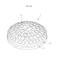
- the curved surface frame 20 may be formed in a semicircular shape, as shown in FIG. 3A , and the transducers 10 may be arranged in a semicircular shape.
- the ultrasonic wave generated by each transducer 10 may irradiate even a wider range compared to the convex-shaped curved surface frame 20 shown in FIG. 2 , and may receive the returned reflection echo in a wider area.
- the lens 40 may be attached on the side at which the transducer 10 of the curved surface frame 20 is disposed, as shown in FIG. 2 .
- the curved surface frame 20 may be formed in a concave shape, which is bent in a second direction 26 extending from the front surface 22 toward the rear surface 24 of curved surface frame 20, opposite the first direction 28, and is concavely recessed in a direction 26, as shown in FIG. 3B .
- the curved surface frame 20 may have a wave shape in which the convex shape and the concave shape are combined. Accordingly, an optimal shape may be selected and applied to the curved surface frame 20, depending on field, technology, or use to which an exemplary embodiment is applied.
- the curved surface frame 20 may be produced in various corresponding shapes so that the transducer 10 may be arranged in various forms depending on the use. Therefore, the curved surface frame 20 may have various shapes such as a bell shape or a spindle shape, as well as the shapes shown in FIGS. 2 to 3C .
- curved surface frame 20 suitable for field to which the transducer module T is applied for example, suitable for the object to be measured by the ultrasonic probe, a more precise and clear image may be obtained. Consequently, an optimized diagnosis and test may be possible.
- the curved surface frame 20 is made of a flexible material, it is possible to somewhat freely design an outer shape of the curved surface frame 20 to be suitable for technologies to which the transducer module T is applied, for example, depending on a sound output direction in a speaker or a shape of an object to be measured or tested. Therefore, the transducer module T may be applied to various technical fields, and a more precise and optimized result may be obtained.
- an auxiliary place unit may be formed on the curved surface frame 20 so that the transducers 10 may be arranged thereon.
- the auxiliary place unit may be, for example, a groove or grooves 21, as shown in FIG. 2 , or a protrusion which protrudes in the form of embossment.
- the groove 21 or a protrusion may be arranged on the front surface 22 of the curved surface frame 20 in a regular pattern by forming an embossment or intaglio pattern 19 on the front surface 22 of the curved surface frame 20.
- the embossment or intaglio pattern may exactly dispose each transducer 10 at a desired set position on the curved surface frame 20, and may allow the set position to be stably held.
- the pattern formed on the curved surface frame 20 may include grooves for tiling so that the transducers 10 may be tiled on the front surface of the curved surface frame 20.
- Each transducer 10 may be arranged according to the pattern formed on the curved surface frame 20 and needs to be fixed to the curved surface frame 20 to maintain the stability.
- an adhesive such as an epoxy resin adhesive, is placed between the transducer 10 and the curved surface frame 20, to bond the transducer 10 to the curved surface frame 20.
- other coupling, fixing, or adhering which may bond or fix the transducer 10 and the curved surface frame 20, may be used.
- the transducer 10 is a cMUT array to generate an ultrasonic wave, which is disposed within the intaglio pattern of the curved surface frame 20.
- the cMUT array may be a 2D array which is configured by a plurality of tiles 11 (for example, thirty two tiles), and one tile 11 may include elements 12 (for example, 256 elements in a 16 x 16 arrangement).
- Each of the elements 12 may include twenty thin films 13.
- the element generates an ultrasonic wave by vibrating in response to application of an electrical signal from, for example, the support frame 30 to be described below in detail.
- Each cMUT array is bonded to the groove 21 of the intaglio pattern of the curved surface frame 20 using an epoxy resin adhesive or the like.
- the cMUT arrays may be directed in respective predetermined directions different from each other depending on the shape of the curved surface frame 20. Consequently, the cMUT arrays may irradiate the ultrasonic wave in various directions or receive the ultrasonic wave from various directions.
- the curved surface frame 20 may be formed with a wire which is connected to the transducers 10 and an external power source or a processor.
- the wire may be formed to pass through the inside of the curved surface frame 20.
- the wire may be connected along the outer surface of the curved surface frame 20.
- the curved surface frame 20 may be produced (a) by deforming a shape of a master mold, for example, by bending the master mold, and pressing a curved surface frame material to the master mold or (b) by pressing together the master mold and the curved surface frame material and deforming the master mold and the curved surface frame material together in the pressed state, as described below in more detail.
- the support frame 30 supports the curved surface frame 20, and assumes a shape of the curved surface frame 20, for example, the convex shape as shown in FIG. 2 .
- the support frame 30 may be mounted on a rear surface 24 of the curved surface frame 20 on which the transducer 10 is not arranged, as shown in FIGS. 2 to 3C .
- the support frame 30 may be formed in a predetermined bent shape.
- the support frame 30 may be formed such that the curved surface frame 20 made of a flexible material may be held and supported in the predetermined shape.
- the support frame 30 may be made of a flexible material.
- the support frame 30 may be made of a material having relatively less flexibility or a more hardened material in order to support the curved surface frame 20, based on an application.
- the support frame 30 may be bonded to the curved surface frame 20 using an epoxy resin adhesive or the like, or may be coupled using any other appropriate coupling or fixing.
- the support frame 30 may be a curved substrate or a flexible substrate to control an electrical signal applied to the transducer 10.
- the support frame 30 may be formed with circuits for the control of the transducer 10, for example, the control of the electrical signal applied to the transducer 10, conversion of energy by the transducer 10, and/or generation of an ultrasonic wave caused by conversion of the electrical signal.
- the lens 40 is attached on and coupled to the front surface of the curved surface frame 20 on which the transducer 10 is arranged.
- the lens 40 protects the transducer 10 and the curved surface frame 20 by covering the curved surface frame 20 and the transducer 10 and blocking the same from the external elements, and focuses light energy, wave energy, or the like.
- the lens 40 may be an acoustic lens.
- a method of producing a curved surface frame applied to the transducer module according to an exemplary embodiment is described below with reference to FIGS. 5 to 7 .
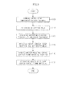
- FIGS. 5 and 7 are flowcharts illustrating a process of producing a curved surface frame.
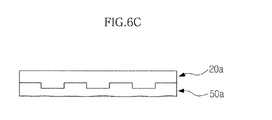
- FIG. 6 is a cross-sectional view for explaining the process of producing the curved surface frame.
- a method of producing the curved surface frame includes polishing or cutting a back surface of a mold to acquire the master mold having flexibility, forming on a front surface thereof an embossment or intaglio pattern, pressing a curved surface frame material against the master mold to form a predetermined intaglio or embossment pattern on the curved surface frame material, bending the mutually pressed master mold and curved surface frame material together, and separating the master mold from the curved surface frame material.
- the curved surface frame 20 may be produced through the following six operations (1) to (6):
- the master mold 50a used in the process of producing the curved surface frame for imprinting the curved surface frame is made of a flexible material which may be easily bent.
- the flexible material for the mold may include silicon, silicon oxide, quartz, glass, polymer, various flexible metals, and the like.
- the mold may be made of the same material as the curved surface frame 20, or may be made of other material.
- the mold 50 is formed with a pattern, for example, the intaglio or embossment pattern in which the transducer 10 is to be disposed on the curved surface frame 20.
- the pattern is formed to follow an array arrangement of the transducer 10, on a front surface 70 of the mold 50.
- the mold 50 may have a thickness w1 of approximately 500 to 700 ⁇ m (operation S100 and FIG. 6(A) ).
- the master mold 50a having a micro thickness is acquired by polishing or cutting another side on which the pattern is not formed, for example, the back surface 72 of the mold 50 to produce a thin master mold 50a with a thickness corresponding to a predetermined standard range (operations S110 and S120 and FIG. 6(B) ).
- a first portion 74 protruding as an embossment is the thicker portion with a thickness w2 of approximately 100 to 150 ⁇ m.
- a second portion 76 recessed as an intaglio is the thinner portion with a thickness w3 of approximately 50 ⁇ m.
- the master mold 50a is thinly polished or cut, and may be sufficiently flexed and smoothly bent.
- the curved surface frame material is formed with a predetermined intaglio or embossment pattern corresponding to the embossment or intaglio pattern of the master mold 50a by pressing the curved surface frame material 20a against the master mold 50a.
- the curved surface frame material 20a may be at least one of silicon, silicon oxide, quartz, glass, polymer, and flexible metal (operation S130 and FIG. 6(C) ).
- the master mold 50a and the curved surface frame material 20a are processed to have a uniformly bent shape as shown in FIG. 6(D) by pressurizing both the master mold 50a and curved surface frame material 20a together.
- the master mold 50a and the curved surface frame material 20a are bent to form the curved surface frame 20 having the shape as shown in FIGS. 2 to 3C (operation S140).
- the curved surface frame 20 having a desired shape is obtained by separating the master mold 50a from the curved surface frame material 20a (operation S150 and FIG. 6(E) ).
- the support frame 30 is mounted to one surface of the acquired curved surface frame 20 while the transducer 10 is bonded to the other surface, thereby obtaining the transducer module T.
- the curved surface frame 20 may be produced by a method different from the above, as follows.
- a method of producing the curved surface frame 20 may include polishing or cutting a back surface of a mold to acquire the master mold having flexibility, forming on a front surface thereof an embossment or intaglio pattern, bending the master mold to acquire a curved master mold, pressing a curved surface frame material against the curved master mold, and separating the curved master mold from the curved surface frame material.
- the method of producing the curved surface frame 20 may include the following six operations (a) to (f):
- the master mold 50a having the micro thickness is similarly acquired in operations (a) to (c) (operations S200 to S220).
- the curved master mold 50a having a curvature corresponding to the curved shape of the curved surface frame to be produced is acquired by processing the master mold 50a to be bent in a certain shape without pressing the curved surface frame material 20a to the master mold 50a (operation S230).
- the curved surface frame 20 having the curved shape is obtained by mutually pressing the master mold 50a having a micro thickness and the above-described curved surface frame material 20a, and separating the master mold 50a from the curved surface frame material 20a (operations S240 and S250).
- the curved surface frame 20 having a curved shape may be obtained by pressing the master mold 50a having a micro thickness and the curved surface frame material 20a together and then processing the same.
- the curved surface frame 20 having a curved shape may be obtained by pre-processing the master mold 50a to have a curved shape before pressing the master mold 50a and the curved surface frame material 20a.
- the curved surface frame 20 may be obtained by the above-described methods, but this is not limiting.
- the curved surface frame 20 may be produced using other methods as applicable.
- the curved surface frame 20 according to an exemplary embodiment is not limited to being produced by the above-described methods.
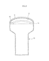
- FIGS. 8 and 9 are a perspective view and a cross-sectional view illustrating an ultrasonic probe according to an exemplary embodiment.
- the transducer module T may be used in the ultrasonic probe 80 of the ultrasonic diagnostic device.
- the ultrasonic probe may include one or more ultrasonic transducers 10, a curved surface frame 20 which is formed in a curved shape on a front surface 82 on which the ultrasonic transducer 10 is disposed, and which is made of a flexible material, and a support frame 30 which is mounted on a rear surface of the curved surface frame 20 to support the curved surface frame, and is formed with a circuit to control an electrical signal applied to the transducer.
- the ultrasonic probe may further include a lens 40 which is mounted on the front surface 82 of the curved surface frame, as shown in FIGS. 8 and 9 .
- the ultrasonic probe may include a probe housing 60 to which the support frame 30 is attached or the support frame 30 and the curved surface frame 20 are attached, or within which the support frame 30 or a portion of the support frame 30 and curved surface frame 20 are accommodated to be fixed, as shown in FIG. 8 .
- the transducer 10 is an ultrasonic transducer which irradiates an ultrasonic wave into an object and receives a reflection echo from the object and may include a magnetostrictive ultrasonic transducer, a piezoelectric ultrasonic transducer, a cMUT, or the like.
- the curved surface frame 20 may be formed in a convex shape, a concave shape, a semicircular shape, or a wave shape, or may have various shapes depending on properties of the object to be irradiated by the ultrasonic wave.
- the curved surface frame 20 may be formed with a pattern in which the transducer 10 may be exactly disposed, as for example, an embossment pattern or an intaglio pattern.
- a plurality of transducers 10 may be arranged on the curved surface frame 20 as a tile.
- a flexible substrate is used as the support frame 30, to control generation of the ultrasonic wave by applying a predetermined power to the transducer 10.
- the housing 60 is directly attached to the support frame 30 using an adhesive or is bonded to the support frame 30 and the curved surface frame 20.
- the housing 60 may stably fix the transducer module T, and a variety of other modules, for example, heat radiation modules or various circuits for operation of the probe device, may be mounted inside the housing 60.
- a handle or the like may be formed at an outer side of the housing 60 for the convenience of a user.
- the ultrasonic probe 80 controls the ultrasonic transducer 10 using a signal generated from a circuit of the support frame 30 and generates an ultrasonic wave.
- the ultrasonic probe receives the reflection echo of the ultrasonic wave, which is reflected from the object, through the ultrasonic transducer 10.
- the received ultrasonic wave is converted into an electrical signal, and the electrical signal is transmitted to an external information processing unit, which includes an image processing portion creating an image from an electrical signal and the like, through a cable 61 or the like.
- a processor which may perform the image processing, may be mounted on a circuit board of the support frame 30 within the housing 60.
- the ultrasonic probe may allow irradiation of the ultrasonic wave in a wide area and collection of the reflection echo by enlarging an area in which the transducer module T is located at the tip of the probe, particularly the area at which the lens comes into contact with the object due to the presence of the curved surface frame 20.
- the ultrasonic transducers are arranged in a large area, thereby receiving or irradiating the ultrasonic wave in a wider range, compared to the related art probe. Accordingly, a large-area ultrasonic system may be configured, and thus a region wider than the region of the related art device may be directly observed. Also, a large quantity of information may be further acquired.
- a more precise and clear image may be created compared to the image acquired by the related art probe.
- the outer shape of the curved surface frame 20 is designed to correspond to the shape of the object or an organ to be imaged, more precise and optimized information may be collected.
- a transducer module including a curved surface frame on which a transducer is arranged, a method of producing the curved surface frame, and an ultrasonic probe including a transducer module as an example to which the transducer module including the curved surface frame is applied.
- the transducer for example an ultrasonic probe of an ultrasonic diagnostic device
- algorithm complexity for beamforming as the transducer is arranged in various 3D forms by deviating from a 2D arrangement of the related art. Consequently, the design of the beamforming system may be simplified and algorithm complexity may be avoided. Therefore, it may be possible to promote manufacturing convenience and efficiency of the various devices using the transducer.
- the transducer may be arranged in a wider variety of forms compared to being arranged on a 2D plane of the related art, thereby irradiating a particular type of energy such as an ultrasonic wave in a wider range, or sensing and observing energy within the wider range in more detail. Therefore, performance of various devices using the exemplary transducer may be improved and enhanced.
Landscapes
- Health & Medical Sciences (AREA)
- Life Sciences & Earth Sciences (AREA)
- Physics & Mathematics (AREA)
- General Health & Medical Sciences (AREA)
- Pathology (AREA)
- Chemical & Material Sciences (AREA)
- Analytical Chemistry (AREA)
- Biochemistry (AREA)
- General Physics & Mathematics (AREA)
- Immunology (AREA)
- Engineering & Computer Science (AREA)
- Mechanical Engineering (AREA)
- Signal Processing (AREA)
- Molecular Biology (AREA)
- Nuclear Medicine, Radiotherapy & Molecular Imaging (AREA)
- Radiology & Medical Imaging (AREA)
- Biomedical Technology (AREA)
- Heart & Thoracic Surgery (AREA)
- Medical Informatics (AREA)
- Biophysics (AREA)
- Surgery (AREA)
- Animal Behavior & Ethology (AREA)
- Public Health (AREA)
- Veterinary Medicine (AREA)
- Acoustics & Sound (AREA)
- Transducers For Ultrasonic Waves (AREA)
- Ultra Sonic Daignosis Equipment (AREA)
Applications Claiming Priority (1)
| Application Number | Priority Date | Filing Date | Title |
|---|---|---|---|
| KR1020120076014A KR101995867B1 (ko) | 2012-07-12 | 2012-07-12 | 곡면프레임을 포함하는 트랜스듀서 모듈, 상기 트랜스듀서 모듈을 포함하는 초음파 프로브 및 상기 곡면프레임을 제조하는 방법 |
Publications (2)
| Publication Number | Publication Date |
|---|---|
| EP2685255A2 true EP2685255A2 (de) | 2014-01-15 |
| EP2685255A3 EP2685255A3 (de) | 2014-08-13 |
Family
ID=48771320
Family Applications (1)
| Application Number | Title | Priority Date | Filing Date |
|---|---|---|---|
| EP13175789.0A Withdrawn EP2685255A3 (de) | 2012-07-12 | 2013-07-09 | Wandlermodul mit gebogenem Oberflächenrahmen, Ultraschallsonde mit dem Wandlermodul und Verfahren zum Herstellen des gebogenen Oberflächenrahmens |
Country Status (4)
| Country | Link |
|---|---|
| US (1) | US20140013850A1 (de) |
| EP (1) | EP2685255A3 (de) |
| KR (1) | KR101995867B1 (de) |
| CN (1) | CN103536314B (de) |
Cited By (7)
| Publication number | Priority date | Publication date | Assignee | Title |
|---|---|---|---|---|
| WO2015183946A1 (en) * | 2014-05-30 | 2015-12-03 | Fujifilm Dimatix, Inc. | Piezoelectric transducer device with lens structures |
| WO2016146467A1 (de) * | 2015-03-13 | 2016-09-22 | Fraunhofer-Gesellschaft zur Förderung der angewandten Forschung e.V. | Schallwandlerarray mit gekoppelten wandlern |
| JPWO2017042997A1 (ja) * | 2015-09-07 | 2018-06-28 | ソニー株式会社 | 超音波アレイ振動子、超音波アレイ振動子の製造方法、超音波プローブ及び超音波診断装置 |
| US10022751B2 (en) | 2014-05-30 | 2018-07-17 | Fujifilm Dimatix, Inc. | Piezoelectric transducer device for configuring a sequence of operational modes |
| US10107645B2 (en) | 2014-05-30 | 2018-10-23 | Fujifilm Dimatix, Inc. | Piezoelectric transducer device with flexible substrate |
| US11808143B2 (en) | 2018-05-14 | 2023-11-07 | Schlumberger Technology Corporation | Methods and apparatus to measure formation features |
| US11921249B2 (en) | 2018-02-08 | 2024-03-05 | Schlumberger Technology Corporation | Ultrasonic acoustic sensors for measuring formation velocities |
Families Citing this family (20)
| Publication number | Priority date | Publication date | Assignee | Title |
|---|---|---|---|---|
| CN103876775B (zh) * | 2012-12-20 | 2016-02-03 | 深圳迈瑞生物医疗电子股份有限公司 | 超声探头的阵元连接元件及其超声探头及超声成像系统 |
| US20150196276A1 (en) * | 2014-01-14 | 2015-07-16 | Samsung Medison Co., Ltd. | Ultrasonic probe and method of manufacturing the same |
| CN104905818A (zh) * | 2015-05-26 | 2015-09-16 | 广州三瑞医疗器械有限公司 | 一种柔性胎心监测传感器及其工作方法 |
| US10006888B2 (en) * | 2016-04-21 | 2018-06-26 | The Boeing Company | MEMS transducers in a phased array coupled to a flexible substrate using carbon nanotubes for conformal ultrasound scanning |
| CN105997146A (zh) * | 2016-06-27 | 2016-10-12 | 麦克思商务咨询(深圳)有限公司 | 超声波传感器 |
| CN106648220B (zh) * | 2016-11-16 | 2023-06-23 | 江西合力泰科技有限公司 | 一种曲面生物识别模组及其制造方法 |
| KR101997865B1 (ko) * | 2017-06-30 | 2019-07-08 | (주)아모레퍼시픽 | 비전도성 물질을 이용한 초음파 미용장치 및 그의 제조방법 |
| CN107192764A (zh) * | 2017-07-07 | 2017-09-22 | 合肥超科电子有限公司 | 一种分体式二次轮式探头支架及探头 |
| KR102031056B1 (ko) * | 2017-07-20 | 2019-10-15 | 한국과학기술연구원 | 사용자 맞춤형 음향렌즈를 이용하는 집속 초음파 자극 장치 |
| CN108178121B (zh) * | 2018-02-07 | 2024-05-03 | 北京先通康桥医药科技有限公司 | 触诊探头及其制造方法 |
| US11493657B2 (en) * | 2018-02-08 | 2022-11-08 | Schlumberger Technology Corporation | Ultrasonic transducers for measuring formation velocities |
| KR102627816B1 (ko) | 2018-10-25 | 2024-01-24 | 삼성디스플레이 주식회사 | 표시 장치 |
| GB201817501D0 (en) * | 2018-10-26 | 2018-12-12 | Dolphitech As | Scanning apparatus |
| KR102201508B1 (ko) * | 2018-11-08 | 2021-01-12 | (주)아모레퍼시픽 | 미용 장치 헤드, 미용 장치 및 미용 장치 헤드를 제조하기 위한 방법 |
| KR102145768B1 (ko) * | 2019-02-12 | 2020-08-19 | 문지환 | 생체 신호 및 사이즈 측정용 플렉시블 트랜스 듀서 제조장치 및 방법 |
| CN115398183A (zh) * | 2020-01-17 | 2022-11-25 | 大不列颠哥伦比亚大学 | 柔性电容式微加工超声换能器阵列 |
| CN111505119B (zh) * | 2020-05-08 | 2020-12-08 | 清华大学 | 柔性超声波疲劳损伤检测装置及其制造方法 |
| CN112050839B (zh) * | 2020-08-11 | 2021-10-15 | 大连理工大学 | 一种随形可变曲率的电磁超声探头及其测量方法 |
| CN113984892B (zh) * | 2021-09-28 | 2023-04-07 | 西安交通大学 | 一种用于球面板材缺陷检测的半柔性阵列式电磁超声探头 |
| CN116359346A (zh) * | 2023-05-30 | 2023-06-30 | 广东汕头超声电子股份有限公司 | 一种基于链式柔性探头的叶片曲面检测设备 |
Citations (1)
| Publication number | Priority date | Publication date | Assignee | Title |
|---|---|---|---|---|
| US20090163910A1 (en) * | 2007-12-21 | 2009-06-25 | Sliwa John W | Template System and Methods |
Family Cites Families (10)
| Publication number | Priority date | Publication date | Assignee | Title |
|---|---|---|---|---|
| JPH0199535A (ja) * | 1987-10-14 | 1989-04-18 | Matsushita Electric Ind Co Ltd | 超音波探触子 |
| JPH11316216A (ja) * | 1998-05-01 | 1999-11-16 | Nippon Steel Corp | 超音波探触子 |
| US6558323B2 (en) * | 2000-11-29 | 2003-05-06 | Olympus Optical Co., Ltd. | Ultrasound transducer array |
| US7285897B2 (en) | 2003-12-31 | 2007-10-23 | General Electric Company | Curved micromachined ultrasonic transducer arrays and related methods of manufacture |
| US7514851B2 (en) * | 2005-07-13 | 2009-04-07 | Siemens Medical Solutions Usa, Inc. | Curved capacitive membrane ultrasound transducer array |
| CN101237947B (zh) * | 2005-08-05 | 2013-03-27 | 皇家飞利浦电子股份有限公司 | 弯曲的二维阵列换能器 |
| JP4860351B2 (ja) * | 2006-05-22 | 2012-01-25 | 富士フイルム株式会社 | 曲面貼着方法および超音波プローブ |
| US20080242979A1 (en) * | 2007-03-30 | 2008-10-02 | Rayette Ann Fisher | Combined X-ray detector and ultrasound imager |
| US8917896B2 (en) * | 2009-09-11 | 2014-12-23 | Bose Corporation | Automated customization of loudspeakers |
| KR101354603B1 (ko) * | 2012-01-02 | 2014-01-23 | 삼성메디슨 주식회사 | 초음파 프로브 및 그 제조방법 |
-
2012
- 2012-07-12 KR KR1020120076014A patent/KR101995867B1/ko not_active Expired - Fee Related
-
2013
- 2013-07-09 EP EP13175789.0A patent/EP2685255A3/de not_active Withdrawn
- 2013-07-11 CN CN201310289882.3A patent/CN103536314B/zh not_active Expired - Fee Related
- 2013-07-12 US US13/940,422 patent/US20140013850A1/en not_active Abandoned
Patent Citations (1)
| Publication number | Priority date | Publication date | Assignee | Title |
|---|---|---|---|---|
| US20090163910A1 (en) * | 2007-12-21 | 2009-06-25 | Sliwa John W | Template System and Methods |
Cited By (10)
| Publication number | Priority date | Publication date | Assignee | Title |
|---|---|---|---|---|
| WO2015183946A1 (en) * | 2014-05-30 | 2015-12-03 | Fujifilm Dimatix, Inc. | Piezoelectric transducer device with lens structures |
| US20150343492A1 (en) * | 2014-05-30 | 2015-12-03 | Arman HAJATI | Piezoelectric transducer device with lens structures |
| US9789515B2 (en) | 2014-05-30 | 2017-10-17 | Fujifilm Dimatix, Inc. | Piezoelectric transducer device with lens structures |
| EP3148714A4 (de) * | 2014-05-30 | 2018-01-17 | Fujifilm Dimatix, Inc. | Piezoelektrische wandlervorrichtung mit linsenstrukturen |
| US10022751B2 (en) | 2014-05-30 | 2018-07-17 | Fujifilm Dimatix, Inc. | Piezoelectric transducer device for configuring a sequence of operational modes |
| US10107645B2 (en) | 2014-05-30 | 2018-10-23 | Fujifilm Dimatix, Inc. | Piezoelectric transducer device with flexible substrate |
| WO2016146467A1 (de) * | 2015-03-13 | 2016-09-22 | Fraunhofer-Gesellschaft zur Förderung der angewandten Forschung e.V. | Schallwandlerarray mit gekoppelten wandlern |
| JPWO2017042997A1 (ja) * | 2015-09-07 | 2018-06-28 | ソニー株式会社 | 超音波アレイ振動子、超音波アレイ振動子の製造方法、超音波プローブ及び超音波診断装置 |
| US11921249B2 (en) | 2018-02-08 | 2024-03-05 | Schlumberger Technology Corporation | Ultrasonic acoustic sensors for measuring formation velocities |
| US11808143B2 (en) | 2018-05-14 | 2023-11-07 | Schlumberger Technology Corporation | Methods and apparatus to measure formation features |
Also Published As
| Publication number | Publication date |
|---|---|
| CN103536314A (zh) | 2014-01-29 |
| EP2685255A3 (de) | 2014-08-13 |
| KR101995867B1 (ko) | 2019-10-01 |
| US20140013850A1 (en) | 2014-01-16 |
| KR20140009673A (ko) | 2014-01-23 |
| CN103536314B (zh) | 2017-06-30 |
Similar Documents
| Publication | Publication Date | Title |
|---|---|---|
| EP2685255A2 (de) | Wandlermodul mit gebogenem Oberflächenrahmen, Ultraschallsonde mit dem Wandlermodul und Verfahren zum Herstellen des gebogenen Oberflächenrahmens | |
| Savoia et al. | A CMUT probe for medical ultrasonography: From microfabrication to system integration | |
| US20150293223A1 (en) | Ultrasonic probe, ultrasonic imaging apparatus, and method of controlling the ultrasonic imaging apparatus | |
| US11800806B2 (en) | Method for manufacturing a multi-cell transducer | |
| US9089875B2 (en) | Ultrasound backing element, transducer and ultrasound probe including the same | |
| JP2022522644A (ja) | フレキシブル超音波アレイ | |
| US20180028159A1 (en) | Rearward acoustic diffusion for ultrasound-on-a-chip transducer array | |
| JP6495322B2 (ja) | Icダイ、超音波プローブ、超音波診断システム及び方法 | |
| KR20160008360A (ko) | 초음파 흡음 부재, 이를 포함하는 초음파 프로브 및 그 제조 방법 | |
| JP6588467B2 (ja) | 音響レンズ及び超音波トランスデューサプローブ | |
| US20180214126A1 (en) | Capacitive micromachined ultrasonic transducer, probe and method of manufacturing the same | |
| JP2000358299A (ja) | 超音波探触子用送受波素子及びその製造方法並びに該送受波素子を用いた超音波探触子 | |
| KR20160043470A (ko) | 초음파 영상 장치 및 초음파 영상 장치의 제어 방법 | |
| KR20150020945A (ko) | 초음파 프로브 및 그 제조 방법 | |
| KR20110003057A (ko) | 초음파 프로브 및 초음파 진단장치 | |
| KR101326531B1 (ko) | 복합형 미세 압전 초음파 트랜스듀서 제작방법 | |
| KR20080058402A (ko) | 방사식 어플리케이션을 위한 2차원 초음파 트랜스듀서 및방법 | |
| Shivalingaprasad et al. | Microfabrication of a 16 MHz 1D-pMUT-Array for Photoacoustic and Ultrasound Imaging | |
| JP2022523175A (ja) | 音響結合インターフェイス | |
| Lee et al. | Silicon nanocolumn-based disposable and flexible ultrasound patches | |
| JP6200246B2 (ja) | 探触子 | |
| Liu et al. | Capacitive micromachined ultrasonic focusing device for ultrasound applications | |
| KR20180068586A (ko) | 초음파 진단 장치용 프로브 |
Legal Events
| Date | Code | Title | Description |
|---|---|---|---|
| PUAI | Public reference made under article 153(3) epc to a published international application that has entered the european phase |
Free format text: ORIGINAL CODE: 0009012 |
|
| AK | Designated contracting states |
Kind code of ref document: A2 Designated state(s): AL AT BE BG CH CY CZ DE DK EE ES FI FR GB GR HR HU IE IS IT LI LT LU LV MC MK MT NL NO PL PT RO RS SE SI SK SM TR |
|
| AX | Request for extension of the european patent |
Extension state: BA ME |
|
| PUAL | Search report despatched |
Free format text: ORIGINAL CODE: 0009013 |
|
| AK | Designated contracting states |
Kind code of ref document: A3 Designated state(s): AL AT BE BG CH CY CZ DE DK EE ES FI FR GB GR HR HU IE IS IT LI LT LU LV MC MK MT NL NO PL PT RO RS SE SI SK SM TR |
|
| AX | Request for extension of the european patent |
Extension state: BA ME |
|
| RIC1 | Information provided on ipc code assigned before grant |
Ipc: G01N 29/24 20060101AFI20140708BHEP Ipc: G01S 15/89 20060101ALI20140708BHEP Ipc: G01N 29/28 20060101ALI20140708BHEP Ipc: B06B 1/06 20060101ALI20140708BHEP |
|
| 17P | Request for examination filed |
Effective date: 20150212 |
|
| RBV | Designated contracting states (corrected) |
Designated state(s): AL AT BE BG CH CY CZ DE DK EE ES FI FR GB GR HR HU IE IS IT LI LT LU LV MC MK MT NL NO PL PT RO RS SE SI SK SM TR |
|
| 17Q | First examination report despatched |
Effective date: 20170822 |
|
| GRAP | Despatch of communication of intention to grant a patent |
Free format text: ORIGINAL CODE: EPIDOSNIGR1 |
|
| INTG | Intention to grant announced |
Effective date: 20190729 |
|
| STAA | Information on the status of an ep patent application or granted ep patent |
Free format text: STATUS: THE APPLICATION IS DEEMED TO BE WITHDRAWN |
|
| 18D | Application deemed to be withdrawn |
Effective date: 20191210 |