EP2685524A1 - Bloc-batterie de véhicule - Google Patents
Bloc-batterie de véhicule Download PDFInfo
- Publication number
- EP2685524A1 EP2685524A1 EP20130176019 EP13176019A EP2685524A1 EP 2685524 A1 EP2685524 A1 EP 2685524A1 EP 20130176019 EP20130176019 EP 20130176019 EP 13176019 A EP13176019 A EP 13176019A EP 2685524 A1 EP2685524 A1 EP 2685524A1
- Authority
- EP
- European Patent Office
- Prior art keywords
- battery
- electric cable
- air flow
- vehicle
- flow passage
- Prior art date
- Legal status (The legal status is an assumption and is not a legal conclusion. Google has not performed a legal analysis and makes no representation as to the accuracy of the status listed.)
- Granted
Links
Images


Classifications
-
- H—ELECTRICITY
- H01—ELECTRIC ELEMENTS
- H01M—PROCESSES OR MEANS, e.g. BATTERIES, FOR THE DIRECT CONVERSION OF CHEMICAL ENERGY INTO ELECTRICAL ENERGY
- H01M10/00—Secondary cells; Manufacture thereof
- H01M10/60—Heating or cooling; Temperature control
- H01M10/62—Heating or cooling; Temperature control specially adapted for specific applications
- H01M10/625—Vehicles
-
- H—ELECTRICITY
- H01—ELECTRIC ELEMENTS
- H01M—PROCESSES OR MEANS, e.g. BATTERIES, FOR THE DIRECT CONVERSION OF CHEMICAL ENERGY INTO ELECTRICAL ENERGY
- H01M10/00—Secondary cells; Manufacture thereof
- H01M10/60—Heating or cooling; Temperature control
- H01M10/65—Means for temperature control structurally associated with the cells
- H01M10/656—Means for temperature control structurally associated with the cells characterised by the type of heat-exchange fluid
- H01M10/6561—Gases
- H01M10/6563—Gases with forced flow, e.g. by blowers
-
- H—ELECTRICITY
- H01—ELECTRIC ELEMENTS
- H01M—PROCESSES OR MEANS, e.g. BATTERIES, FOR THE DIRECT CONVERSION OF CHEMICAL ENERGY INTO ELECTRICAL ENERGY
- H01M10/00—Secondary cells; Manufacture thereof
- H01M10/60—Heating or cooling; Temperature control
- H01M10/61—Types of temperature control
- H01M10/613—Cooling or keeping cold
-
- H—ELECTRICITY
- H01—ELECTRIC ELEMENTS
- H01M—PROCESSES OR MEANS, e.g. BATTERIES, FOR THE DIRECT CONVERSION OF CHEMICAL ENERGY INTO ELECTRICAL ENERGY
- H01M50/00—Constructional details or processes of manufacture of the non-active parts of electrochemical cells other than fuel cells, e.g. hybrid cells
- H01M50/20—Mountings; Secondary casings or frames; Racks, modules or packs; Suspension devices; Shock absorbers; Transport or carrying devices; Holders
- H01M50/204—Racks, modules or packs for multiple batteries or multiple cells
- H01M50/207—Racks, modules or packs for multiple batteries or multiple cells characterised by their shape
- H01M50/209—Racks, modules or packs for multiple batteries or multiple cells characterised by their shape adapted for prismatic or rectangular cells
-
- H—ELECTRICITY
- H01—ELECTRIC ELEMENTS
- H01M—PROCESSES OR MEANS, e.g. BATTERIES, FOR THE DIRECT CONVERSION OF CHEMICAL ENERGY INTO ELECTRICAL ENERGY
- H01M50/00—Constructional details or processes of manufacture of the non-active parts of electrochemical cells other than fuel cells, e.g. hybrid cells
- H01M50/20—Mountings; Secondary casings or frames; Racks, modules or packs; Suspension devices; Shock absorbers; Transport or carrying devices; Holders
- H01M50/249—Mountings; Secondary casings or frames; Racks, modules or packs; Suspension devices; Shock absorbers; Transport or carrying devices; Holders specially adapted for aircraft or vehicles, e.g. cars or trains
-
- H—ELECTRICITY
- H01—ELECTRIC ELEMENTS
- H01M—PROCESSES OR MEANS, e.g. BATTERIES, FOR THE DIRECT CONVERSION OF CHEMICAL ENERGY INTO ELECTRICAL ENERGY
- H01M50/00—Constructional details or processes of manufacture of the non-active parts of electrochemical cells other than fuel cells, e.g. hybrid cells
- H01M50/20—Mountings; Secondary casings or frames; Racks, modules or packs; Suspension devices; Shock absorbers; Transport or carrying devices; Holders
- H01M50/271—Lids or covers for the racks or secondary casings
-
- H—ELECTRICITY
- H01—ELECTRIC ELEMENTS
- H01M—PROCESSES OR MEANS, e.g. BATTERIES, FOR THE DIRECT CONVERSION OF CHEMICAL ENERGY INTO ELECTRICAL ENERGY
- H01M50/00—Constructional details or processes of manufacture of the non-active parts of electrochemical cells other than fuel cells, e.g. hybrid cells
- H01M50/20—Mountings; Secondary casings or frames; Racks, modules or packs; Suspension devices; Shock absorbers; Transport or carrying devices; Holders
- H01M50/296—Mountings; Secondary casings or frames; Racks, modules or packs; Suspension devices; Shock absorbers; Transport or carrying devices; Holders characterised by terminals of battery packs
-
- H—ELECTRICITY
- H01—ELECTRIC ELEMENTS
- H01M—PROCESSES OR MEANS, e.g. BATTERIES, FOR THE DIRECT CONVERSION OF CHEMICAL ENERGY INTO ELECTRICAL ENERGY
- H01M10/00—Secondary cells; Manufacture thereof
- H01M10/60—Heating or cooling; Temperature control
- H01M10/66—Heat-exchange relationships between the cells and other systems, e.g. central heating systems or fuel cells
- H01M10/663—Heat-exchange relationships between the cells and other systems, e.g. central heating systems or fuel cells the system being an air-conditioner or an engine
-
- H—ELECTRICITY
- H01—ELECTRIC ELEMENTS
- H01M—PROCESSES OR MEANS, e.g. BATTERIES, FOR THE DIRECT CONVERSION OF CHEMICAL ENERGY INTO ELECTRICAL ENERGY
- H01M2220/00—Batteries for particular applications
- H01M2220/20—Batteries in motive systems, e.g. vehicle, ship, plane
-
- H—ELECTRICITY
- H01—ELECTRIC ELEMENTS
- H01M—PROCESSES OR MEANS, e.g. BATTERIES, FOR THE DIRECT CONVERSION OF CHEMICAL ENERGY INTO ELECTRICAL ENERGY
- H01M50/00—Constructional details or processes of manufacture of the non-active parts of electrochemical cells other than fuel cells, e.g. hybrid cells
- H01M50/50—Current conducting connections for cells or batteries
- H01M50/502—Interconnectors for connecting terminals of adjacent batteries; Interconnectors for connecting cells outside a battery casing
- H01M50/503—Interconnectors for connecting terminals of adjacent batteries; Interconnectors for connecting cells outside a battery casing characterised by the shape of the interconnectors
-
- H—ELECTRICITY
- H01—ELECTRIC ELEMENTS
- H01M—PROCESSES OR MEANS, e.g. BATTERIES, FOR THE DIRECT CONVERSION OF CHEMICAL ENERGY INTO ELECTRICAL ENERGY
- H01M50/00—Constructional details or processes of manufacture of the non-active parts of electrochemical cells other than fuel cells, e.g. hybrid cells
- H01M50/50—Current conducting connections for cells or batteries
- H01M50/502—Interconnectors for connecting terminals of adjacent batteries; Interconnectors for connecting cells outside a battery casing
- H01M50/509—Interconnectors for connecting terminals of adjacent batteries; Interconnectors for connecting cells outside a battery casing characterised by the type of connection, e.g. mixed connections
- H01M50/51—Connection only in series
-
- Y—GENERAL TAGGING OF NEW TECHNOLOGICAL DEVELOPMENTS; GENERAL TAGGING OF CROSS-SECTIONAL TECHNOLOGIES SPANNING OVER SEVERAL SECTIONS OF THE IPC; TECHNICAL SUBJECTS COVERED BY FORMER USPC CROSS-REFERENCE ART COLLECTIONS [XRACs] AND DIGESTS
- Y02—TECHNOLOGIES OR APPLICATIONS FOR MITIGATION OR ADAPTATION AGAINST CLIMATE CHANGE
- Y02E—REDUCTION OF GREENHOUSE GAS [GHG] EMISSIONS, RELATED TO ENERGY GENERATION, TRANSMISSION OR DISTRIBUTION
- Y02E60/00—Enabling technologies; Technologies with a potential or indirect contribution to GHG emissions mitigation
- Y02E60/10—Energy storage using batteries
Definitions
- the present invention relates to a battery pack of a vehicle which contains a battery for driving the vehicle, and more particularly, to the battery pack which is mounted on a vehicle such as an electric vehicle and a hybrid vehicle.
- a battery pack which is mounted on a vehicle such as an electric vehicle and a hybrid vehicle is provided with a battery including a plurality of battery cells, and a battery case for containing the battery.
- the battery pack is attached to a lower face of a floor panel of the vehicle. Because an upper face of the floor panel forms a part of a vehicle room, the battery pack is disposed outside of the vehicle room.
- An electric power of the battery is supplied to a driving motor by way of an electric cable which connects the battery to the driving motor.
- actuating the driving motor wheels are rotated thereby to drive the vehicle.
- JP-A-2011-68187 there is disclosed a hybrid vehicle which is provided with a battery pack having a cooling unit, a driving motor which is actuated by an electric power of the battery pack, an inverter for controlling the driving motor, an electric cable for connecting the battery pack to the inverter, and an engine.
- This battery pack of the hybrid vehicle is installed in a baggage room in a rear part of the vehicle.
- the inverter and the driving motor are installed in a front part of the vehicle, and the diving motor is connected to front wheels.
- the electric cable is arranged along a vehicle anteroposterior direction of the vehicle, in a center part of the vehicle in a vehicle width direction, in a state covered with a cover member.
- the battery pack is provided with an air cooling fan, and a duct for feeding a cooling air which is supplied from the air cooling fan, to the battery.
- the duct is disposed in parallel with the electric cable, passing inside the cover member.
- the electric cable to be arranged toward the rear wheels is disposed at a lateral side of the battery pack, that is, in an end part of the vehicle in the vehicle width direction, there is such anxiety that the electric cable may be damaged due to splash of stones, attack of strange matters while the vehicle is running, or deformation of a vehicle body with an external force from a lateral side of the vehicle, and so on. Therefore, considering safety, the electric cable is disposed in the center part of the vehicle in the vehicle width direction, by passing it through the battery case of the battery pack.
- the electric cable On occasion of disposing the electric cable in the battery case, the electric cable is fixed to the battery case or the like with fixing clips, for the purpose of preventing movements of the electric cable (hereinafter referred to as "flappering") due to vibration of the vehicle, which may damage surrounding members.
- the electric cable After both ends of the electric cable are respectively connected to objects to be connected, the electric cable is fixed to a predetermined position which has been set in advance by layout or so.
- the electric cable has a longer length than a length which has been determined according to the layout or so, since there is a large tolerance in the length of the electric cable in a longitudinal direction.
- a worker tries to fix the electric cable to the predetermined position inside the battery case with the fixing clips, after the both ends of the electric cable have been respectively connected to the objects to be connected, it is sometimes impossible to arrange the electric cable at a predetermined wiring position, since the electric cable is too long.
- the electric cable is unable to be fixed to the predetermined position with the fixing clip, in some cases.
- the presently disclosed subject matter may provide a battery pack of a vehicle which can stably support an electric cable, by absorbing a superfluous length of the electric cable.
- the battery pack of a vehicle may comprise: a battery; a battery case including: a battery tray which contains the battery; and a battery cover which is mounted on the battery tray and which covers the battery; a cooling unit provided in an end part of the battery case in a first direction that is a longitudinal direction of the battery case, and configured to supply a cooling air into the battery case; an air flow passage provided above the battery and extending along the first direction, in a center part in a second direction perpendicular to the first direction inside the battery case, one end of the air flow passage connected to the cooling unit; and an electric cable arranged between the air flow passage and the battery cover, along the first direction, and configured to supply an electric power of the battery to a motor.
- a concave part in a shape of a groove may be formed on an upper face of an upper wall of the air flow passage along the first direction, and the electric cable may be arranged in the concave part.
- the concave part of the air flow passage may have a width capable of absorbing a superfluous length of the electric cable when both ends of the electric cable are respectively connected to objects to be connected.
- the electric cable may include a positive side cable and a negative side cable
- the concave part of the air flow passage may include two recesses which are different from each other in depth
- the positive side cable and the negative side cable may be respectively arranged in the two recesses.
- a floor panel of the vehicle may be provided with a floor tunnel which is protruded upward and which extends along a vehicle anteroposterior direction, in a center part of the floor panel in a vehicle width direction, the battery cover may have a convex part which is protruded upward and which extends along the first direction, in the center part in the second direction, and the air flow passage and the electric cable may be arranged in the convex part, and the convex part may be provided inside the floor tunnel.
- An elastic material may be provided between the electric cable and the battery cover, and the electric cable may be pressed with the elastic material against the air flow passage.
- the battery may include a plurality of batteries, and bus bars for connecting the batteries may include a bus bar which is disposed in the center part in the second direction and which is arranged between a lower face of the air flow passage and upper faces of the batteries.
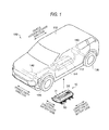
- Fig. 1 is a perspective view schematically showing structure of a vehicle which is provided with a battery pack in a first embodiment according to the invention.
- a vehicle 100 has a floor panel 111 in a lower part of a vehicle body 110, and a battery pack 10 is attached to a lower face of the floor panel 111.
- An upper face of the floor panel 111 forms a part of a vehicle room, and therefore, the battery pack 10 is disposed outside of the vehicle room.
- the battery pack 10 has batteries 20, and a battery case 50 for containing the batteries 20.
- the battery pack 10 is disposed in such a manner that a longer side (a longitudinal direction) of the battery case 50 is aligned with a vehicle anteroposterior direction of the vehicle 100, and a shorter side (a lateral direction perpendicular to the longitudinal direction) of the battery case 50 is aligned with a vehicle width direction of the vehicle 100.
- the longitudinal direction of the battery case 50 is referred to as the vehicle anteroposterior direction of the vehicle 100
- the lateral direction of the battery case 50 is referred to as the vehicle width direction of the vehicle 100.
- the vehicle 100 on which the battery pack 10 is mounted there are a hybrid vehicle and an electric vehicle.
- the battery pack 10 is connected to a front wheel driving motor 140 and a rear wheel driving motor 150 for rotating front wheels 120 and rear wheels 130 respectively.
- Each of the motors 140, 150 receive an output of the battery pack 10 to generate motor energy for driving the vehicle 100. Outputs of the motors 140, 150 are respectively transmitted to the front wheels 120 and the rear wheels 130.
- Fig. 2 is a schematic sectional view of the battery pack 10 in the first embodiment according to the invention, and the floor panel 111, as seen from a front side of the vehicle 100.
- the floor panel 111 has a floor tunnel 112 which is protruded upward and which extends along the vehicle anteroposterior direction, in a center part of the floor panel 111 in the vehicle width direction.
- the floor tunnel 112 is provided between a driver's seat and an assistant driver's seat in the vehicle width direction.
- a convex part 11 of the battery pack 10 is positioned inside the floor tunnel 112. Structure of the battery pack 10 will be described below.
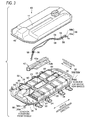
- Fig. 3 is an exploded perspective view of the battery pack 10 in the first embodiment according to the invention
- Fig. 4 is a plan view of the battery pack 10 in the first embodiment according to the invention, in a state where a battery cover is removed.
- the battery pack 10 is provided with a plurality of batteries 20, the battery case 50, and a cooling unit 60 for supplying a cooling air into the battery case 50.
- the battery case 50 includes a battery tray 30 which constitutes a lower part of the battery case 50, and a battery cover 40 which constitutes an upper part of the battery case 50.
- a plurality of the batteries 20 are contained in a space which is formed between the battery tray 30 and the battery cover 40.
- two pieces of the batteries 20 are arranged in the vehicle width direction, and five pieces of the batteries 20 are arranged in the vehicle anteroposterior direction.
- Each of the batteries 20 includes a plurality of battery cells 21.
- each of the batteries 20 includes eight pieces of the battery cells 21, but the number of the battery cells 21 is not limited to eight.
- the batteries 20 are fixed to the battery tray 30 by means of battery holders 90.
- the two batteries 20 which are adjacent to each other in the vehicle anteroposterior direction are interconnected by bus bars 23, 24.
- the bus bars 23 are disposed along the vehicle anteroposterior direction, in a center part of the battery case 50 in the vehicle width direction.
- Each of the bus bars 23 has a substantially U-shape, and disposed on the two batteries 20 so as to stride across the two batteries 20 which are adjacent to each other in the vehicle anteroposterior direction.
- One end of the bus bar 23 is connected to a negative terminal of the battery 20 at a front side, while the other end is connected to a positive terminal of the battery 20 at a rear side, out of the batteries 20 adjacent to each other in the vehicle anteroposterior direction.
- the bus bars 24 are disposed along the vehicle out of the batteries 20 adjacent to each other in the vehicle anteroposterior direction, in outer end parts of the battery case 50 in the vehicle width direction.
- Each of the bus bars 24 has a plate-like shape, and is disposed at a lower position than top ends of the two batteries 20.
- One end of the bus bar 24 is connected to a negative terminal of the battery 20 at the front side, while the other end is connected to a positive terminal of the battery 20 at the rear side, out of the batteries 20 adjacent to each other in the vehicle anteroposterior direction.
- the battery pack 10 is formed as an assembly of the batteries 20.
- An electric cable 55 for the front wheels and an electric cable 56 for the rear wheels are provided for the purpose of supplying an electric power of the battery pack 10 respectively to the front wheel driving motor 140 and the rear wheel driving motor 150.
- the cables 55 and 56 respectively include positive side cables 55a, 56a and negative side cables 55b, 56b.
- the positive side cables 55a, 56a and negative side cables 55b, 56b are respectively connected to the positive terminal 57a and the negative terminal 57b of the battery pack 10.
- the positive terminal 57a and the negative terminal 57b of the battery pack 10 are disposed in a space S in a front end part of the battery tray 30. In this space S, there is provided no battery 20.
- the electric cable 55 for the front wheels is arranged from the space S to a front side of the vehicle, through an opening 34 which is formed on a front end face of the battery tray 30.
- the electric cable 56 for the rear wheels is arranged from the space S to a rear side of the vehicle, through an opening 35 which is formed on a rear end face of the battery tray 30.
- the electric cable 56 for the rear wheels is provided above the batteries 20 in the center part of the battery case 50 in the vehicle width direction.
- the positive side cable 56a and the negative side cable 56b of the electric cable 56 for the rear wheels which are arranged in the battery case 50 are respectively fixed to the battery holders 90 by means of fixing clips 58.
- each of the cables 56a and 56b is fixed at three positions, but the number of the fixing positions is not limited to three.
- the convex part 11 of the battery cover 40 is formed so as to protrude upward and so as to extend along the vehicle anteroposterior direction, in a center part of the battery cover 40 in the vehicle width direction.
- the electric cable 56 for the rear wheels is arranged in this convex part 11. Specific arrangement of the electric cable 56 for the rear wheels inside the convex part 11 will be described below.
- the cooling unit 60 is installed in the space S of the battery tray 30.
- the cooling unit 60 is provided with an evaporator 61, a duct 70 which is connected to the evaporator 61 at its one end, and a fan unit 80 which is connected to the other end of the duct 70.
- an introducing passage for supplying a cooling medium, and a discharging passage for discharging the cooling medium which is evaporated inside the evaporator 61 are connected to the evaporator 61.
- These introducing passage and discharging passage are connected to an external compressor or the like, which is not shown.
- An air flow passage 42 for supplying the air which is cooled by the evaporator 61 to the respective batteries 20 is connected to the fan unit 80.
- the air flow passage 42 is provided above the batteries 20 along the vehicle anteroposterior direction, in the center part of the battery case 50 in the vehicle width direction.
- the air flow passage 42 is formed of resin material having insulating performance.
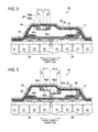
- Fig. 5 is a sectional view showing a region surrounding the convex part 11 of the battery pack 10 in the first embodiment according to the invention.
- the air flow passage 42 is provided in the convex part 11 of the battery cover 40. Inside the convex part 11, the air flow passage 42 is provided between the bus bars 23, which are disposed in the center part of the battery case 50 in the vehicle width direction, and the electric cable 56 for the rear wheels.
- the air flow passage 42 has a concave part 42a, which is protruded downward and extends along the vehicle anteroposterior direction, on an upper face 42b of an upper wall of the air flow passage 42.
- the electric cable 56 for the rear wheels are arranged in this concave part 42a.
- the concave part 42a has such a width that the positive side cable 56a and the negative side cable 56b of the cable 56 for the rear wheels can be arranged in a snaky shape.
- the width of the concave part 42a a width twice as large as a diameter of the positive side cable 56a and the negative side cable 56b is secured for each of the cables 56a, 56b, so that the cables 56a, 56b can be respectively arranged in a snaky shape.
- the width of the concave part 42a is set to be four times as large as the diameter of the positive side cable 56a (the negative side cable 56b).
- the electric cable 56 for the rear wheels is fixed to a predetermined position which has been set in advance according to a layout or so, using the fixing clips 58, after both ends of the cable 56 have been respectively connected to the terminals or so.
- the cable 56 in a snaky shape inside the concave part 42a, it is possible to absorb a superfluous length of the cable 56 for the rear wheels.
- the width of the concave part 42a the width twice as large as the diameter of the cables 56a, 56b is secured for each of the cables 56a, 56b.
- the width of the concave part 42a is not limited to this value, but may be larger than twice.
- the width of the concave part 42a may be determined in advance according to the layout or so, taking an amount of the air flow into consideration.
- a pad 44 formed of elastic material is attached to an inner face of the battery cover 40. In this manner, it is possible to prevent abrasion of coverings of the positive side cable 56a and the negative side cable 56b, when the positive side cable 56a and the negative side cable 56b come into contact with the battery cover 40.
- the electric cable 56 for the rear wheels is arranged in a gap between the air flow passage 42, which is provided in the battery case 50, and the battery cover 40, it is possible to arrange the electric cable 56 for the rear wheels in a snaky shape in this gap. As the results, a superfluous length of the electric cable 56 for the rear wheels can be absorbed. In this manner, it is possible to prevent the electric cable 56 for the rear wheels from failing to be fixed to the position which has been set in advance, when the cable 56 is fixed with the fixing clips 58.
- the electric cable 56 for the rear wheels is arranged between the air flow passage 42 formed of the resin material in the battery case 50 and the battery cover 40, the electric cable 56 for the rear wheels can be insulated from the batteries 20 and the bus bars 23, utilizing the space formed by the air flow passage 42. As the results, it is possible to prevent the electric cable 56 for the rear wheels from coming into contact with the batteries 20 due to deformation of the vehicle body, when an external force is exerted from a lateral side of the vehicle 100. In this manner, high insulating performance can be secured.
- the electric cable 56 for the rear wheels is arranged between the air flow passage 42 and the battery cover 40, there is no necessity of providing a new space for arranging the electric cable 56 for the rear wheels, between the floor panel 111 and the battery case 50. Accordingly, the layout of the floor panel 111, the battery case 50 and so on need not be changed.
- a sectional area of the air flow passage 42 to be decreased by providing the electric cable 56 for the rear wheels can be made as small as possible.
- the concave part 42a has the width capable of absorbing a superfluous length of the electric cable 56 for the rear wheels, when the both ends of the electric cable 56 for the rear wheels are connected to the objects to be connected. Therefore, it is possible to arrange the electric cable 56 for the rear wheels in the concave part 42a, with an allowance. In this manner, the superfluous length of the electric cable 56 for the rear wheels can be reliably absorbed.
- the air flow passage 42 and the electric cable 56 for the rear wheels are provided in the convex part 11 of the battery cover 40, a thickness of the battery case 50 in other region than the convex part 11 can be reduced.
- the convex part 11 of the battery cover 40 is positioned inside the floor tunnel 112, it is possible to reduce a length of the battery case 50 protruding downward from the floor panel 111.
- the battery cover 40 is provided with the pad 44, it is possible to prevent abrasion of the covering of the electric cable 56 for the rear wheels, even though the electric cable 56 for the rear wheels flappers due to vibration of the vehicle 100. Still further, it is possible to prevent occurrence of frictional noise, when the electric cable 56 for the rear wheels flappers and comes into contact with the battery cover 40 and the air flow passage 42.
- Fig. 6 is a sectional view showing a region surrounding a convex part 11 of a battery pack 91 in the second embodiment according to the invention.
- an air flow passage 92 of the battery pack 91 is provided with a concave part 92a having recesses of different depths in two steps.
- the concave part 92a has a first recess 92d which is formed on a bottom face 92c of the concave part 92a, and a second recess 92e which is further protruded downward than the bottom face 92c.
- the positive side cable 56a and the negative side cable 56b are respectively arranged in the second recess 92e and in the first recess 92d. In short, the positive side cable 56a and the negative side cable 56b are respectively arranged in the different recesses.
- the positive side cable 56a and the negative side cable 56b are respectively arranged in the second recess 92e and in the first recess 92d, the invention is not limited to this arrangement.
- a width of the first recess 92d of the concave part 92a is set to be three times as large as the diameter of the negative side cable 56b
- a width of the second recess 92e of the concave part 92a is set to be three times as large as the diameter of the positive side cable 56a.
- the widths of the first recess 92d and the second recess 92e are determined in advance by layout or so, considering relation between the widths and an amount of the air flow.
- the width of the first recess 92d and the width of the second recess 92e are equal, but the widths are not limited to this.
- the width of the first recess 92d may be set to be twice as large as the diameter of the negative side cable 56b
- the width of the second recess 92e may be set to be three times as large as the diameter of the positive side cable 56a. In this case, a space is formed above the positive side cable 56a which is arranged in the second recess 92e.
- this space as a space for moving the negative side cables 56b which is arranged in the first recess 92d, it is possible to make the width of the first recess 92d smaller than the width of the second recess 92e. In this manner, it is possible to reduce the sectional area of the air flow passage 92 to be decreased by providing the concave part 92a in the air flow passage 92.
- the width of the first recess 92d may be set to be three times as large as the diameter of the negative side cable 56b, and the width of the second recess 92e may be set to be twice as large as the diameter of the positive side cable 56a.
- the battery pack 91 of the vehicle 100 in the above described embodiment since the first recess 92d and the second recess 92e are provided in the concave part 92a, and the positive side cable 56a and the negative side cable 56b are respectively arranged in the second recess 92e and in the first recess 92d, it is possible to reliably arrange the cables 56a, 56b in a snaky shape. As the results, even in case where a plurality of the cables 56a, 56b are arranged in the concave part 92a, superfluous lengths of the cables 56a, 56b can be reliably absorbed.
- the electric cable is arranged in a gap between the air flow passage which is provided in the battery case and the battery cover, it is possible to arrange the electric cable in a snaky shape in this gap. As the results, a superfluous length of the electric cable can be absorbed. In this manner, it is possible to prevent the electric cable from failing to be assembled to the battery case, because of displacement of the fixing clips, when the electric cable is arranged in the battery case of the battery pack.
- the electric cable is arranged between the air flow passage and the battery cover, the electric cable can be insulated from the batteries, utilizing a space formed by the air flow passage. As the results, it is possible to prevent the electric cable from coming into contact with the batteries due to deformation of a vehicle body, when an external force is exerted from a lateral side of the vehicle. In this manner, high insulating performance can be secured.
- the electric cable is arranged between the air flow passage and the battery cover, there is no necessity of providing a new space for arranging the electric cable between the battery case and a floor panel of the vehicle body to which the battery case is attached. Accordingly, a layout of the floor panel, the battery case and so on need not be changed.
- a sectional area of the air flow passage to be decreased by providing the electric cable can be made as small as possible.
- the concave part has the width capable of absorbing a superfluous length of the electric cable, when the both ends of the electric cable are respectively connected to the objects to be connected. Therefore, it is possible to arrange the electric cable in the concave part, with an allowance, in a snaky shape. In this manner, the superfluous length of the electric cable can be reliably absorbed.
- the electric cable for supplying the electric power of the battery includes the positive side cable and the negative side cable.
- the electric cable for supplying the electric power of the battery includes the positive side cable and the negative side cable.
- at least two cables are arranged in the concave part. Since the recesses are formed in two steps in the concave part, and the positive side cable and the negative side cable are respectively arranged in the different recesses, it is possible to reliably arrange the cables in a snaky shape. As the results, even in case where a plurality of the cables are arranged in the concave part, superfluous lengths of the respective cables can be reliably absorbed.
- the air flow passage and the electric cable are provided in the convex part of the battery cover, a thickness of the battery case in other region than the convex part can be reduced.
- the convex part of the battery cover is positioned inside the floor tunnel, it is possible to reduce a length of the battery case protruding downward from the floor panel.
- fixing means for fixing the electric cable to the air flow passage is not required. In this manner, a space for providing the fixing means is not required, and so, it is possible to secure a wide sectional area of the air flow passage.
- the battery cover is provided with the elastic material, it is possible to prevent abrasion of the covering of the electric cable, even though the electric cable flappers due to vibration of the vehicle. Still further, it is possible to prevent occurrence of frictional noise, when the electric cable flappers and comes into contact with the battery cover and the air flow passage.
- the bus bars which are provided in the center part in the vehicle width direction are disposed between the lower face of the air flow passage and the upper face of the batteries, the bus bars can be insulated from the batteries, utilizing the space formed by the air flow passage. As the results, it is possible to prevent the electric cable from coming into contact with the bus bars due to deformation of the vehicle body, when an external force is exerted from the lateral side of the vehicle. In this manner, high insulating performance can be secured.
- a battery pack of a vehicle which can stably support an electric cable, by absorbing a superfluous length of the electric cable.
- the invention can be applied to a vehicle such as an electric vehicle or a hybrid vehicle which is equipped with a battery pack containing batteries for driving the vehicle.
Landscapes
- Chemical & Material Sciences (AREA)
- Chemical Kinetics & Catalysis (AREA)
- Electrochemistry (AREA)
- General Chemical & Material Sciences (AREA)
- Engineering & Computer Science (AREA)
- Manufacturing & Machinery (AREA)
- Aviation & Aerospace Engineering (AREA)
- Arrangement Or Mounting Of Propulsion Units For Vehicles (AREA)
- Battery Mounting, Suspending (AREA)
- Electric Propulsion And Braking For Vehicles (AREA)
- Secondary Cells (AREA)
Applications Claiming Priority (1)
| Application Number | Priority Date | Filing Date | Title |
|---|---|---|---|
| JP2012157230A JP6020959B2 (ja) | 2012-07-13 | 2012-07-13 | 車両の電池パック |
Publications (2)
| Publication Number | Publication Date |
|---|---|
| EP2685524A1 true EP2685524A1 (fr) | 2014-01-15 |
| EP2685524B1 EP2685524B1 (fr) | 2017-08-23 |
Family
ID=48771333
Family Applications (1)
| Application Number | Title | Priority Date | Filing Date |
|---|---|---|---|
| EP13176019.1A Active EP2685524B1 (fr) | 2012-07-13 | 2013-07-11 | Bloc-batterie de véhicule |
Country Status (4)
| Country | Link |
|---|---|
| US (1) | US9490460B2 (fr) |
| EP (1) | EP2685524B1 (fr) |
| JP (1) | JP6020959B2 (fr) |
| CN (1) | CN103538456B (fr) |
Cited By (4)
| Publication number | Priority date | Publication date | Assignee | Title |
|---|---|---|---|---|
| FR3067680A1 (fr) * | 2017-06-14 | 2018-12-21 | Peugeot Citroen Automobiles Sa | Systeme de gestion thermique d’un vehicule hybride ou electrique comportant deux boucles de fluide caloporteur |
| CN109994669A (zh) * | 2017-12-29 | 2019-07-09 | 上海电巴新能源科技有限公司 | 电池包总成及含其的电动车 |
| EP4049899A1 (fr) * | 2021-02-26 | 2022-08-31 | Suzuki Motor Corporation | Équipement électrique |
| EP4049900A1 (fr) * | 2021-02-26 | 2022-08-31 | Suzuki Motor Corporation | Structure de protection de faisceaux de câbles |
Families Citing this family (63)
| Publication number | Priority date | Publication date | Assignee | Title |
|---|---|---|---|---|
| US9216638B2 (en) * | 2011-12-09 | 2015-12-22 | Honda Motor Co., Ltd. | Structure for mounting battery pack on vehicle |
| JP6171946B2 (ja) * | 2014-01-22 | 2017-08-02 | トヨタ自動車株式会社 | 電池パックを搭載した自動車 |
| JP6284016B2 (ja) * | 2014-03-25 | 2018-02-28 | 三菱自動車工業株式会社 | 電動車両 |
| JP6390285B2 (ja) * | 2014-09-05 | 2018-09-19 | 株式会社豊田自動織機 | 電池パック |
| DE102014018746A1 (de) * | 2014-12-16 | 2016-06-16 | Audi Ag | Batterie für ein Kraftfahrzeug und Kraftfahrzeug |
| JP6344692B2 (ja) * | 2015-01-13 | 2018-06-20 | トヨタ自動車東日本株式会社 | 車両のフロア構造 |
| US10468645B2 (en) * | 2015-01-29 | 2019-11-05 | Ford Global Technologies, Llc | Vehicle frame mounted high voltage battery assembly |
| US10358169B2 (en) * | 2015-03-06 | 2019-07-23 | Ford Global Technologies, Llc | Coverless battery assembly for electrified vehicle |
| US10017037B2 (en) | 2016-02-09 | 2018-07-10 | Nio Usa, Inc. | Vehicle having a battery pack directly attached to the cross rails of a frame structure |
| US10160344B2 (en) | 2016-02-09 | 2018-12-25 | Nio Nextev Limited | Modular battery assembly |
| CN107293663B (zh) * | 2016-04-11 | 2020-11-20 | 比亚迪股份有限公司 | 一种用于安装动力电池的车用托盘组件及汽车 |
| CN107293659B (zh) * | 2016-04-11 | 2019-12-20 | 比亚迪股份有限公司 | 一种电池托盘、电池托盘组件和电动汽车 |
| CN107293660B (zh) * | 2016-04-11 | 2020-11-20 | 比亚迪股份有限公司 | 一种用于安装动力电池的车用托盘组件及汽车 |
| CN107293662A (zh) * | 2016-04-11 | 2017-10-24 | 比亚迪股份有限公司 | 一种用于安装动力电池的车用托盘组件及汽车 |
| KR101857796B1 (ko) | 2016-08-03 | 2018-06-20 | 삼성전자주식회사 | 모바일 엑스선 장치 |
| WO2018033880A2 (fr) | 2016-08-17 | 2018-02-22 | Shape Corp. | Structure de support et de protection de batterie pour un véhicule |
| JP6419123B2 (ja) * | 2016-09-13 | 2018-11-07 | 本田技研工業株式会社 | 電力機器ユニット及び車両 |
| EP3566253B1 (fr) | 2017-01-04 | 2022-12-28 | Shape Corp. | Structure de support de batterie pour un véhicule |
| KR101871365B1 (ko) | 2017-01-11 | 2018-06-26 | 삼성전자주식회사 | 모바일 엑스선 장치 |
| DE102017207188A1 (de) * | 2017-04-28 | 2018-10-31 | Robert Bosch Gmbh | Batterie mit einer Mehrzahl an Batteriezellen |
| US10483510B2 (en) | 2017-05-16 | 2019-11-19 | Shape Corp. | Polarized battery tray for a vehicle |
| WO2018213383A1 (fr) | 2017-05-16 | 2018-11-22 | Shape Corp. | Support de batterie de véhicule à 'éléments de retenue et de support de batterie intégrés |
| US10886513B2 (en) | 2017-05-16 | 2021-01-05 | Shape Corp. | Vehicle battery tray having tub-based integration |
| WO2019055658A2 (fr) | 2017-09-13 | 2019-03-21 | Shape Corp. | Plateau de batterie de véhicule à paroi périphérique tubulaire |
| US12347879B2 (en) | 2017-09-13 | 2025-07-01 | Shape Corp. | Vehicle battery tray with tubular peripheral wall |
| DE112018005556T5 (de) | 2017-10-04 | 2020-06-25 | Shape Corp. | Batterieträger-bodenbaugruppe für elektrofahrzeuge |
| WO2019169080A1 (fr) | 2018-03-01 | 2019-09-06 | Shape Corp. | Système de refroidissement intégré à un bac de batterie de véhicule |
| US11688910B2 (en) | 2018-03-15 | 2023-06-27 | Shape Corp. | Vehicle battery tray having tub-based component |
| JP7059737B2 (ja) * | 2018-03-22 | 2022-04-26 | トヨタ自動車株式会社 | 電池パック |
| US10622612B2 (en) | 2018-04-19 | 2020-04-14 | Ford Global Technologies, Llc | Low voltage bus bar in high voltage battery enclosure |
| JP7309326B2 (ja) * | 2018-06-19 | 2023-07-18 | 株式会社日立インダストリアルプロダクツ | 蓄電池用トレー及び電子機器 |
| JP7107034B2 (ja) * | 2018-07-03 | 2022-07-27 | 日産自動車株式会社 | バッテリの端子接続構造 |
| JP6724091B2 (ja) | 2018-09-06 | 2020-07-15 | 本田技研工業株式会社 | ハイブリッド車両 |
| JP6721654B2 (ja) * | 2018-10-11 | 2020-07-15 | 本田技研工業株式会社 | 電動車両のバッテリパック |
| JP2020104560A (ja) * | 2018-12-26 | 2020-07-09 | 株式会社オートネットワーク技術研究所 | ワイヤーハーネスアセンブリ、及びワイヤーハーネスアセンブリの取り付け構造 |
| JP7056544B2 (ja) * | 2018-12-26 | 2022-04-19 | 株式会社オートネットワーク技術研究所 | ワイヤハーネス配索部材 |
| JP7059923B2 (ja) | 2018-12-26 | 2022-04-26 | 株式会社オートネットワーク技術研究所 | 電源装置、及び車両 |
| US10476061B1 (en) * | 2018-12-31 | 2019-11-12 | Chongqing Jinkang New Energy Vehicle Co., Ltd. | Electric vehicle cabin floor structure |
| JP6850312B2 (ja) * | 2019-02-01 | 2021-03-31 | 本田技研工業株式会社 | 車両 |
| DE102019001338A1 (de) | 2019-02-26 | 2020-08-27 | Daimler Ag | Anordnung einer Leitung an einem Gehäuseteil für ein Kraftfahrzeug |
| DE102019106424A1 (de) * | 2019-03-13 | 2020-09-17 | Bayerische Motoren Werke Aktiengesellschaft | Energiespeichereinrichtung für ein Kraftfahrzeug, Kraftfahrzeug sowie Herstellungsverfahren |
| DE102019130854A1 (de) * | 2019-03-18 | 2020-09-24 | Dr. Ing. H.C. F. Porsche Aktiengesellschaft | Haltevorrichtung für Strom- und Signalleiter einer Traktionsbatterie eines Kraftfahrzeugs |
| JP7331448B2 (ja) * | 2019-05-15 | 2023-08-23 | マツダ株式会社 | 電動車両の下部車体構造 |
| JP6876744B2 (ja) * | 2019-05-16 | 2021-05-26 | 本田技研工業株式会社 | 車両用バッテリユニット |
| JP7345730B2 (ja) * | 2019-08-20 | 2023-09-19 | マツダ株式会社 | ハーネス配設構造 |
| JP7626068B2 (ja) | 2019-08-23 | 2025-02-04 | 株式会社Gsユアサ | 蓄電装置 |
| DE102019127942A1 (de) * | 2019-10-16 | 2021-04-22 | Bayerische Motoren Werke Aktiengesellschaft | Karosserie für einen elektrisch betreibbaren Kraftwagen |
| JP7284107B2 (ja) * | 2020-01-17 | 2023-05-30 | トヨタ自動車株式会社 | 車両構造 |
| JP7252148B2 (ja) * | 2020-01-30 | 2023-04-04 | トヨタ自動車株式会社 | 電気自動車の車体下部構造 |
| JP7238820B2 (ja) * | 2020-02-05 | 2023-03-14 | トヨタ自動車株式会社 | 電池パックの車載構造 |
| WO2021220027A1 (fr) * | 2020-04-28 | 2021-11-04 | 日産自動車株式会社 | Structure de plancher de véhicule électrique |
| KR102772825B1 (ko) | 2020-04-29 | 2025-02-24 | 주식회사 엘지에너지솔루션 | 전지팩 및 이를 포함하는 디바이스 |
| KR102928721B1 (ko) * | 2020-10-23 | 2026-02-19 | 주식회사 엘지에너지솔루션 | 배터리 팩, 및 자동차 |
| JP7481235B2 (ja) * | 2020-11-19 | 2024-05-10 | 本田技研工業株式会社 | 車体下部構造 |
| KR20220092267A (ko) * | 2020-12-24 | 2022-07-01 | 현대모비스 주식회사 | 차량의 배터리 시스템 |
| JP7557699B2 (ja) * | 2020-12-28 | 2024-09-30 | スズキ株式会社 | 車両用バッテリパック |
| JP7559549B2 (ja) * | 2020-12-28 | 2024-10-02 | スズキ株式会社 | 車両用バッテリパック |
| CN115149171A (zh) * | 2021-03-30 | 2022-10-04 | 比亚迪股份有限公司 | 电池包动力连接系统及车辆 |
| JP7676971B2 (ja) * | 2021-06-08 | 2025-05-15 | 日産自動車株式会社 | バッテリの搭載構造 |
| KR20230040203A (ko) * | 2021-09-15 | 2023-03-22 | 현대자동차주식회사 | 배터리 팩 |
| WO2023112793A1 (fr) * | 2021-12-14 | 2023-06-22 | 株式会社クボタ | Véhicule de travail électrique |
| CN115384622B (zh) * | 2022-08-29 | 2023-11-24 | 浙江极氪智能科技有限公司 | 车身组件和车辆 |
| DE102023100401A1 (de) | 2023-01-10 | 2024-07-11 | Ford Global Technologies, Llc | Batterieanordnung und Verfahren zur Herstellung einer Batterieanordnung |
Citations (8)
| Publication number | Priority date | Publication date | Assignee | Title |
|---|---|---|---|---|
| JP2001006643A (ja) * | 1999-06-21 | 2001-01-12 | Sanyo Electric Co Ltd | 電源装置 |
| US6472098B1 (en) * | 1998-11-30 | 2002-10-29 | Sony Corporation | Battery device for loading on a mobile system |
| WO2006059469A1 (fr) * | 2004-11-30 | 2006-06-08 | Nec Corporation | Ensemble electrique emballe dans du film |
| JP2008140631A (ja) * | 2006-11-30 | 2008-06-19 | Sanyo Electric Co Ltd | 車両用の電源装置 |
| JP2009099490A (ja) * | 2007-10-19 | 2009-05-07 | Toyota Motor Corp | 電池パック構造 |
| JP2011068187A (ja) | 2009-09-24 | 2011-04-07 | Suzuki Motor Corp | 車両の高電圧ケーブルの配策構造 |
| JP2011116321A (ja) | 2009-12-07 | 2011-06-16 | Mitsubishi Motors Corp | 電池パックの冷却構造 |
| WO2012028927A2 (fr) * | 2010-08-31 | 2012-03-08 | Toyota Jidosha Kasbushiki Kaisha | Dispositif de stockage d'électricité et véhicule associé |
Family Cites Families (3)
| Publication number | Priority date | Publication date | Assignee | Title |
|---|---|---|---|---|
| JP5257220B2 (ja) * | 2009-04-23 | 2013-08-07 | 株式会社デンソー | 電池システム |
| JP5640382B2 (ja) | 2009-05-26 | 2014-12-17 | 日産自動車株式会社 | 車両のバッテリアセンブリ冷却構造、および、ウォータージャケット付きバッテリアセンブリ |
| WO2012023753A2 (fr) * | 2010-08-16 | 2012-02-23 | 주식회사 엘지화학 | Module de batterie avec structure compacte possédant d'excellentes caractéristiques de rayonnement thermique, et pack de batterie de moyenne ou grande taille |
-
2012
- 2012-07-13 JP JP2012157230A patent/JP6020959B2/ja active Active
-
2013
- 2013-07-11 EP EP13176019.1A patent/EP2685524B1/fr active Active
- 2013-07-12 US US13/940,368 patent/US9490460B2/en active Active
- 2013-07-15 CN CN201310295850.4A patent/CN103538456B/zh active Active
Patent Citations (8)
| Publication number | Priority date | Publication date | Assignee | Title |
|---|---|---|---|---|
| US6472098B1 (en) * | 1998-11-30 | 2002-10-29 | Sony Corporation | Battery device for loading on a mobile system |
| JP2001006643A (ja) * | 1999-06-21 | 2001-01-12 | Sanyo Electric Co Ltd | 電源装置 |
| WO2006059469A1 (fr) * | 2004-11-30 | 2006-06-08 | Nec Corporation | Ensemble electrique emballe dans du film |
| JP2008140631A (ja) * | 2006-11-30 | 2008-06-19 | Sanyo Electric Co Ltd | 車両用の電源装置 |
| JP2009099490A (ja) * | 2007-10-19 | 2009-05-07 | Toyota Motor Corp | 電池パック構造 |
| JP2011068187A (ja) | 2009-09-24 | 2011-04-07 | Suzuki Motor Corp | 車両の高電圧ケーブルの配策構造 |
| JP2011116321A (ja) | 2009-12-07 | 2011-06-16 | Mitsubishi Motors Corp | 電池パックの冷却構造 |
| WO2012028927A2 (fr) * | 2010-08-31 | 2012-03-08 | Toyota Jidosha Kasbushiki Kaisha | Dispositif de stockage d'électricité et véhicule associé |
Cited By (5)
| Publication number | Priority date | Publication date | Assignee | Title |
|---|---|---|---|---|
| FR3067680A1 (fr) * | 2017-06-14 | 2018-12-21 | Peugeot Citroen Automobiles Sa | Systeme de gestion thermique d’un vehicule hybride ou electrique comportant deux boucles de fluide caloporteur |
| CN109994669A (zh) * | 2017-12-29 | 2019-07-09 | 上海电巴新能源科技有限公司 | 电池包总成及含其的电动车 |
| CN109994669B (zh) * | 2017-12-29 | 2021-11-26 | 上海电巴新能源科技有限公司 | 电池包总成及含其的电动车 |
| EP4049899A1 (fr) * | 2021-02-26 | 2022-08-31 | Suzuki Motor Corporation | Équipement électrique |
| EP4049900A1 (fr) * | 2021-02-26 | 2022-08-31 | Suzuki Motor Corporation | Structure de protection de faisceaux de câbles |
Also Published As
| Publication number | Publication date |
|---|---|
| US20140017546A1 (en) | 2014-01-16 |
| CN103538456A (zh) | 2014-01-29 |
| JP6020959B2 (ja) | 2016-11-02 |
| JP2014022092A (ja) | 2014-02-03 |
| EP2685524B1 (fr) | 2017-08-23 |
| US9490460B2 (en) | 2016-11-08 |
| CN103538456B (zh) | 2016-08-10 |
Similar Documents
| Publication | Publication Date | Title |
|---|---|---|
| EP2685524B1 (fr) | Bloc-batterie de véhicule | |
| KR102835262B1 (ko) | 자동차용 언더 바디 | |
| JP5967477B2 (ja) | 電池パック | |
| JP4539717B2 (ja) | 二次電池の冷却構造 | |
| JP4363350B2 (ja) | 二次電池の冷却構造 | |
| CN105835679B (zh) | 安装在车架上的高压电池总成 | |
| EP2528134B1 (fr) | Bac d'accumulateur pour véhicule | |
| JP6520424B2 (ja) | 車両用バッテリパックの取付け構造 | |
| CN102858579B (zh) | 车体后部的电器设备的搭载结构 | |
| CN104302501B (zh) | 车辆 | |
| EP2000345A1 (fr) | Structure de fixation de bloc d'alimentation en courant | |
| CN105313660A (zh) | 用于电气化车辆蓄电池阵列的阵列架设计 | |
| JP7284107B2 (ja) | 車両構造 | |
| EP2873566B1 (fr) | Structure de câblage à haute tension dans un véhicule | |
| JP2015081042A (ja) | 電気車両 | |
| CN105313662A (zh) | 用于电气化车辆蓄电池阵列的阵列架设计 | |
| US20160233467A1 (en) | Impact Absorbing Elements Attached to the Outer Surface of a Battery Enclosure | |
| CN105313661A (zh) | 用于电气化车辆蓄电池阵列的阵列架设计 | |
| JP2019117688A (ja) | 電池パック | |
| JP4363391B2 (ja) | 電気部品の取り付け構造 | |
| JP5998825B2 (ja) | 高電圧ハーネスの保護構造 | |
| CN109256601B (zh) | 车辆用电池组 | |
| CN103298636B (zh) | 电动汽车 | |
| WO2013073491A1 (fr) | Unité de commande de puissance pour véhicule électrique | |
| KR101504078B1 (ko) | 배터리 팩 |
Legal Events
| Date | Code | Title | Description |
|---|---|---|---|
| PUAI | Public reference made under article 153(3) epc to a published international application that has entered the european phase |
Free format text: ORIGINAL CODE: 0009012 |
|
| 17P | Request for examination filed |
Effective date: 20130711 |
|
| AK | Designated contracting states |
Kind code of ref document: A1 Designated state(s): AL AT BE BG CH CY CZ DE DK EE ES FI FR GB GR HR HU IE IS IT LI LT LU LV MC MK MT NL NO PL PT RO RS SE SI SK SM TR |
|
| AX | Request for extension of the european patent |
Extension state: BA ME |
|
| 17Q | First examination report despatched |
Effective date: 20151210 |
|
| GRAP | Despatch of communication of intention to grant a patent |
Free format text: ORIGINAL CODE: EPIDOSNIGR1 |
|
| RIC1 | Information provided on ipc code assigned before grant |
Ipc: H01M 10/6563 20140101ALI20170109BHEP Ipc: H01M 10/625 20140101ALI20170109BHEP Ipc: H01M 2/10 20060101AFI20170109BHEP Ipc: H01M 10/613 20140101ALI20170109BHEP |
|
| INTG | Intention to grant announced |
Effective date: 20170127 |
|
| GRAS | Grant fee paid |
Free format text: ORIGINAL CODE: EPIDOSNIGR3 |
|
| GRAA | (expected) grant |
Free format text: ORIGINAL CODE: 0009210 |
|
| AK | Designated contracting states |
Kind code of ref document: B1 Designated state(s): AL AT BE BG CH CY CZ DE DK EE ES FI FR GB GR HR HU IE IS IT LI LT LU LV MC MK MT NL NO PL PT RO RS SE SI SK SM TR |
|
| REG | Reference to a national code |
Ref country code: GB Ref legal event code: FG4D |
|
| REG | Reference to a national code |
Ref country code: CH Ref legal event code: EP |
|
| REG | Reference to a national code |
Ref country code: AT Ref legal event code: REF Ref document number: 922216 Country of ref document: AT Kind code of ref document: T Effective date: 20170915 |
|
| REG | Reference to a national code |
Ref country code: IE Ref legal event code: FG4D |
|
| REG | Reference to a national code |
Ref country code: DE Ref legal event code: R096 Ref document number: 602013025358 Country of ref document: DE |
|
| REG | Reference to a national code |
Ref country code: NL Ref legal event code: MP Effective date: 20170823 |
|
| REG | Reference to a national code |
Ref country code: LT Ref legal event code: MG4D |
|
| REG | Reference to a national code |
Ref country code: AT Ref legal event code: MK05 Ref document number: 922216 Country of ref document: AT Kind code of ref document: T Effective date: 20170823 |
|
| PG25 | Lapsed in a contracting state [announced via postgrant information from national office to epo] |
Ref country code: NO Free format text: LAPSE BECAUSE OF FAILURE TO SUBMIT A TRANSLATION OF THE DESCRIPTION OR TO PAY THE FEE WITHIN THE PRESCRIBED TIME-LIMIT Effective date: 20171123 Ref country code: SE Free format text: LAPSE BECAUSE OF FAILURE TO SUBMIT A TRANSLATION OF THE DESCRIPTION OR TO PAY THE FEE WITHIN THE PRESCRIBED TIME-LIMIT Effective date: 20170823 Ref country code: FI Free format text: LAPSE BECAUSE OF FAILURE TO SUBMIT A TRANSLATION OF THE DESCRIPTION OR TO PAY THE FEE WITHIN THE PRESCRIBED TIME-LIMIT Effective date: 20170823 Ref country code: NL Free format text: LAPSE BECAUSE OF FAILURE TO SUBMIT A TRANSLATION OF THE DESCRIPTION OR TO PAY THE FEE WITHIN THE PRESCRIBED TIME-LIMIT Effective date: 20170823 Ref country code: AT Free format text: LAPSE BECAUSE OF FAILURE TO SUBMIT A TRANSLATION OF THE DESCRIPTION OR TO PAY THE FEE WITHIN THE PRESCRIBED TIME-LIMIT Effective date: 20170823 Ref country code: LT Free format text: LAPSE BECAUSE OF FAILURE TO SUBMIT A TRANSLATION OF THE DESCRIPTION OR TO PAY THE FEE WITHIN THE PRESCRIBED TIME-LIMIT Effective date: 20170823 Ref country code: HR Free format text: LAPSE BECAUSE OF FAILURE TO SUBMIT A TRANSLATION OF THE DESCRIPTION OR TO PAY THE FEE WITHIN THE PRESCRIBED TIME-LIMIT Effective date: 20170823 |
|
| PG25 | Lapsed in a contracting state [announced via postgrant information from national office to epo] |
Ref country code: RS Free format text: LAPSE BECAUSE OF FAILURE TO SUBMIT A TRANSLATION OF THE DESCRIPTION OR TO PAY THE FEE WITHIN THE PRESCRIBED TIME-LIMIT Effective date: 20170823 Ref country code: ES Free format text: LAPSE BECAUSE OF FAILURE TO SUBMIT A TRANSLATION OF THE DESCRIPTION OR TO PAY THE FEE WITHIN THE PRESCRIBED TIME-LIMIT Effective date: 20170823 Ref country code: PL Free format text: LAPSE BECAUSE OF FAILURE TO SUBMIT A TRANSLATION OF THE DESCRIPTION OR TO PAY THE FEE WITHIN THE PRESCRIBED TIME-LIMIT Effective date: 20170823 Ref country code: IS Free format text: LAPSE BECAUSE OF FAILURE TO SUBMIT A TRANSLATION OF THE DESCRIPTION OR TO PAY THE FEE WITHIN THE PRESCRIBED TIME-LIMIT Effective date: 20171223 Ref country code: LV Free format text: LAPSE BECAUSE OF FAILURE TO SUBMIT A TRANSLATION OF THE DESCRIPTION OR TO PAY THE FEE WITHIN THE PRESCRIBED TIME-LIMIT Effective date: 20170823 Ref country code: BG Free format text: LAPSE BECAUSE OF FAILURE TO SUBMIT A TRANSLATION OF THE DESCRIPTION OR TO PAY THE FEE WITHIN THE PRESCRIBED TIME-LIMIT Effective date: 20171123 Ref country code: GR Free format text: LAPSE BECAUSE OF FAILURE TO SUBMIT A TRANSLATION OF THE DESCRIPTION OR TO PAY THE FEE WITHIN THE PRESCRIBED TIME-LIMIT Effective date: 20171124 |
|
| PG25 | Lapsed in a contracting state [announced via postgrant information from national office to epo] |
Ref country code: DK Free format text: LAPSE BECAUSE OF FAILURE TO SUBMIT A TRANSLATION OF THE DESCRIPTION OR TO PAY THE FEE WITHIN THE PRESCRIBED TIME-LIMIT Effective date: 20170823 Ref country code: RO Free format text: LAPSE BECAUSE OF FAILURE TO SUBMIT A TRANSLATION OF THE DESCRIPTION OR TO PAY THE FEE WITHIN THE PRESCRIBED TIME-LIMIT Effective date: 20170823 Ref country code: CZ Free format text: LAPSE BECAUSE OF FAILURE TO SUBMIT A TRANSLATION OF THE DESCRIPTION OR TO PAY THE FEE WITHIN THE PRESCRIBED TIME-LIMIT Effective date: 20170823 |
|
| REG | Reference to a national code |
Ref country code: DE Ref legal event code: R097 Ref document number: 602013025358 Country of ref document: DE |
|
| PG25 | Lapsed in a contracting state [announced via postgrant information from national office to epo] |
Ref country code: IT Free format text: LAPSE BECAUSE OF FAILURE TO SUBMIT A TRANSLATION OF THE DESCRIPTION OR TO PAY THE FEE WITHIN THE PRESCRIBED TIME-LIMIT Effective date: 20170823 Ref country code: SK Free format text: LAPSE BECAUSE OF FAILURE TO SUBMIT A TRANSLATION OF THE DESCRIPTION OR TO PAY THE FEE WITHIN THE PRESCRIBED TIME-LIMIT Effective date: 20170823 Ref country code: EE Free format text: LAPSE BECAUSE OF FAILURE TO SUBMIT A TRANSLATION OF THE DESCRIPTION OR TO PAY THE FEE WITHIN THE PRESCRIBED TIME-LIMIT Effective date: 20170823 Ref country code: SM Free format text: LAPSE BECAUSE OF FAILURE TO SUBMIT A TRANSLATION OF THE DESCRIPTION OR TO PAY THE FEE WITHIN THE PRESCRIBED TIME-LIMIT Effective date: 20170823 |
|
| REG | Reference to a national code |
Ref country code: FR Ref legal event code: PLFP Year of fee payment: 6 |
|
| PLBE | No opposition filed within time limit |
Free format text: ORIGINAL CODE: 0009261 |
|
| STAA | Information on the status of an ep patent application or granted ep patent |
Free format text: STATUS: NO OPPOSITION FILED WITHIN TIME LIMIT |
|
| 26N | No opposition filed |
Effective date: 20180524 |
|
| PG25 | Lapsed in a contracting state [announced via postgrant information from national office to epo] |
Ref country code: SI Free format text: LAPSE BECAUSE OF FAILURE TO SUBMIT A TRANSLATION OF THE DESCRIPTION OR TO PAY THE FEE WITHIN THE PRESCRIBED TIME-LIMIT Effective date: 20170823 |
|
| REG | Reference to a national code |
Ref country code: CH Ref legal event code: PL |
|
| GBPC | Gb: european patent ceased through non-payment of renewal fee |
Effective date: 20180711 |
|
| PG25 | Lapsed in a contracting state [announced via postgrant information from national office to epo] |
Ref country code: LU Free format text: LAPSE BECAUSE OF NON-PAYMENT OF DUE FEES Effective date: 20180711 Ref country code: MC Free format text: LAPSE BECAUSE OF FAILURE TO SUBMIT A TRANSLATION OF THE DESCRIPTION OR TO PAY THE FEE WITHIN THE PRESCRIBED TIME-LIMIT Effective date: 20170823 |
|
| REG | Reference to a national code |
Ref country code: BE Ref legal event code: MM Effective date: 20180731 |
|
| REG | Reference to a national code |
Ref country code: IE Ref legal event code: MM4A |
|
| PG25 | Lapsed in a contracting state [announced via postgrant information from national office to epo] |
Ref country code: CH Free format text: LAPSE BECAUSE OF NON-PAYMENT OF DUE FEES Effective date: 20180731 Ref country code: IE Free format text: LAPSE BECAUSE OF NON-PAYMENT OF DUE FEES Effective date: 20180711 Ref country code: LI Free format text: LAPSE BECAUSE OF NON-PAYMENT OF DUE FEES Effective date: 20180731 Ref country code: GB Free format text: LAPSE BECAUSE OF NON-PAYMENT OF DUE FEES Effective date: 20180711 |
|
| PG25 | Lapsed in a contracting state [announced via postgrant information from national office to epo] |
Ref country code: BE Free format text: LAPSE BECAUSE OF NON-PAYMENT OF DUE FEES Effective date: 20180731 |
|
| PG25 | Lapsed in a contracting state [announced via postgrant information from national office to epo] |
Ref country code: MT Free format text: LAPSE BECAUSE OF NON-PAYMENT OF DUE FEES Effective date: 20180711 |
|
| PG25 | Lapsed in a contracting state [announced via postgrant information from national office to epo] |
Ref country code: TR Free format text: LAPSE BECAUSE OF FAILURE TO SUBMIT A TRANSLATION OF THE DESCRIPTION OR TO PAY THE FEE WITHIN THE PRESCRIBED TIME-LIMIT Effective date: 20170823 |
|
| PG25 | Lapsed in a contracting state [announced via postgrant information from national office to epo] |
Ref country code: HU Free format text: LAPSE BECAUSE OF FAILURE TO SUBMIT A TRANSLATION OF THE DESCRIPTION OR TO PAY THE FEE WITHIN THE PRESCRIBED TIME-LIMIT; INVALID AB INITIO Effective date: 20130711 Ref country code: PT Free format text: LAPSE BECAUSE OF FAILURE TO SUBMIT A TRANSLATION OF THE DESCRIPTION OR TO PAY THE FEE WITHIN THE PRESCRIBED TIME-LIMIT Effective date: 20170823 |
|
| PG25 | Lapsed in a contracting state [announced via postgrant information from national office to epo] |
Ref country code: CY Free format text: LAPSE BECAUSE OF FAILURE TO SUBMIT A TRANSLATION OF THE DESCRIPTION OR TO PAY THE FEE WITHIN THE PRESCRIBED TIME-LIMIT Effective date: 20170823 Ref country code: MK Free format text: LAPSE BECAUSE OF NON-PAYMENT OF DUE FEES Effective date: 20170823 |
|
| PG25 | Lapsed in a contracting state [announced via postgrant information from national office to epo] |
Ref country code: AL Free format text: LAPSE BECAUSE OF FAILURE TO SUBMIT A TRANSLATION OF THE DESCRIPTION OR TO PAY THE FEE WITHIN THE PRESCRIBED TIME-LIMIT Effective date: 20170823 |
|
| REG | Reference to a national code |
Ref country code: DE Ref legal event code: R079 Ref document number: 602013025358 Country of ref document: DE Free format text: PREVIOUS MAIN CLASS: H01M0002100000 Ipc: H01M0050200000 |
|
| PGFP | Annual fee paid to national office [announced via postgrant information from national office to epo] |
Ref country code: FR Payment date: 20250610 Year of fee payment: 13 |
|
| PGFP | Annual fee paid to national office [announced via postgrant information from national office to epo] |
Ref country code: DE Payment date: 20250528 Year of fee payment: 13 |