EP2685577A1 - Boîte de câblage et procédé pour son installation - Google Patents
Boîte de câblage et procédé pour son installation Download PDFInfo
- Publication number
- EP2685577A1 EP2685577A1 EP11859962.0A EP11859962A EP2685577A1 EP 2685577 A1 EP2685577 A1 EP 2685577A1 EP 11859962 A EP11859962 A EP 11859962A EP 2685577 A1 EP2685577 A1 EP 2685577A1
- Authority
- EP
- European Patent Office
- Prior art keywords
- top plate
- wiring box
- opening
- lid body
- lid
- Prior art date
- Legal status (The legal status is an assumption and is not a legal conclusion. Google has not performed a legal analysis and makes no representation as to the accuracy of the status listed.)
- Withdrawn
Links
Images





Classifications
-
- H—ELECTRICITY
- H02—GENERATION; CONVERSION OR DISTRIBUTION OF ELECTRIC POWER
- H02G—INSTALLATION OF ELECTRIC CABLES OR LINES, OR OF COMBINED OPTICAL AND ELECTRIC CABLES OR LINES
- H02G3/00—Installations of electric cables or lines or protective tubing therefor in or on buildings, equivalent structures or vehicles
- H02G3/02—Details
- H02G3/08—Distribution boxes; Connection or junction boxes
- H02G3/12—Distribution boxes; Connection or junction boxes for flush mounting
- H02G3/121—Distribution boxes; Connection or junction boxes for flush mounting in plain walls
-
- H—ELECTRICITY
- H02—GENERATION; CONVERSION OR DISTRIBUTION OF ELECTRIC POWER
- H02G—INSTALLATION OF ELECTRIC CABLES OR LINES, OR OF COMBINED OPTICAL AND ELECTRIC CABLES OR LINES
- H02G3/00—Installations of electric cables or lines or protective tubing therefor in or on buildings, equivalent structures or vehicles
- H02G3/02—Details
- H02G3/08—Distribution boxes; Connection or junction boxes
- H02G3/14—Fastening of cover or lid to box
-
- A—HUMAN NECESSITIES
- A47—FURNITURE; DOMESTIC ARTICLES OR APPLIANCES; COFFEE MILLS; SPICE MILLS; SUCTION CLEANERS IN GENERAL
- A47B—TABLES; DESKS; OFFICE FURNITURE; CABINETS; DRAWERS; GENERAL DETAILS OF FURNITURE
- A47B21/00—Tables or desks for office equipment, e.g. typewriters, keyboards
- A47B21/06—Tables or desks for office equipment, e.g. typewriters, keyboards characterised by means for holding, fastening or concealing cables
-
- H—ELECTRICITY
- H02—GENERATION; CONVERSION OR DISTRIBUTION OF ELECTRIC POWER
- H02G—INSTALLATION OF ELECTRIC CABLES OR LINES, OR OF COMBINED OPTICAL AND ELECTRIC CABLES OR LINES
- H02G3/00—Installations of electric cables or lines or protective tubing therefor in or on buildings, equivalent structures or vehicles
- H02G3/02—Details
- H02G3/08—Distribution boxes; Connection or junction boxes
- H02G3/081—Bases, casings or covers
-
- H—ELECTRICITY
- H02—GENERATION; CONVERSION OR DISTRIBUTION OF ELECTRIC POWER
- H02G—INSTALLATION OF ELECTRIC CABLES OR LINES, OR OF COMBINED OPTICAL AND ELECTRIC CABLES OR LINES
- H02G3/00—Installations of electric cables or lines or protective tubing therefor in or on buildings, equivalent structures or vehicles
- H02G3/02—Details
- H02G3/08—Distribution boxes; Connection or junction boxes
- H02G3/12—Distribution boxes; Connection or junction boxes for flush mounting
- H02G3/123—Distribution boxes; Connection or junction boxes for flush mounting in thin walls
-
- A—HUMAN NECESSITIES
- A47—FURNITURE; DOMESTIC ARTICLES OR APPLIANCES; COFFEE MILLS; SPICE MILLS; SUCTION CLEANERS IN GENERAL
- A47B—TABLES; DESKS; OFFICE FURNITURE; CABINETS; DRAWERS; GENERAL DETAILS OF FURNITURE
- A47B2200/00—General construction of tables or desks
- A47B2200/008—Tables or desks having means for applying electronic or electric devices
- A47B2200/0082—Cable inlet in worktop or desk, e.g. grommet
-
- Y—GENERAL TAGGING OF NEW TECHNOLOGICAL DEVELOPMENTS; GENERAL TAGGING OF CROSS-SECTIONAL TECHNOLOGIES SPANNING OVER SEVERAL SECTIONS OF THE IPC; TECHNICAL SUBJECTS COVERED BY FORMER USPC CROSS-REFERENCE ART COLLECTIONS [XRACs] AND DIGESTS
- Y10—TECHNICAL SUBJECTS COVERED BY FORMER USPC
- Y10T—TECHNICAL SUBJECTS COVERED BY FORMER US CLASSIFICATION
- Y10T29/00—Metal working
- Y10T29/49—Method of mechanical manufacture
- Y10T29/49826—Assembling or joining
Definitions
- the present invention relates to a wiring box including a lid body which opens and closes an opening of a top plate, and a method of mounting the same.
- a wiring box including a lid body which opens and closes an opening for wiring, which vertically penetrates through a top plate of a table, is known.
- the wiring box is mounted to the lower surface of the top plate, and a duct at the lower portion of the wiring box can accommodate power supply devices such as sockets, LAN cables, and the like.
- a duct at the lower portion of the wiring box can accommodate power supply devices such as sockets, LAN cables, and the like.
- it is configured to use the socket or the like accommodated in the duct at the lower surface of the top plate via the opening of the top plate.
- the lid body of the wiring box is configured to be selectively opened and closed between a state of closing the opening and a state of opening the opening. Particularly, in the open state of the opening, it is configured to accommodate the lid body inside the wiring box (for example, Patent Literature 1).
- the wiring box is configured to be fallen into the opening from above the top plate, and a flange formed in the periphery of the wiring box is caught on the edge of the opening so that positioning of the lid body of the wiring box and the surface of the top plate of the table in the height direction is performed.
- the thickness of the top plate varies depending on the types of the table, in order to allow a height between the lid body and a mounting metal fitting of the wiring box to be constant, the height of the mounting metal fitting of the wiring box needs to be changed according to the thickness of the top plate. Otherwise, there is also a method which employs mounting metal fittings having an adjusting mechanism corresponding to each top plate thickness.
- a mounting process requires labor, and there is a problem in terms of a selection of components and cost.
- the present invention relates to a wiring box including a lid body which opens and closes an opening of a top plate, and provides a wiring box which enables a lid body of the wiring box and a top plate surface to form a flat and uniform surface by a simple configuration and enables positioning of the wiring box to be easily performed at the time of mounting the wiring box even when a top plate has a different thickness, and a method of mounting the same.
- the invention disclosed in claim 1 of the present invention is a wiring box including: a lid body which opens and closes an opening of a top plate, wherein the lid body is rotatably supported by the other end of a rotating arm of which one end is rotatably supported inside the opening, the lid body is elevated while being held in a substantially vertical state inside the opening of the top plate by rotation of the rotating arm, and the opening is closed by rotation of the lid body at a surface of the opening of the top plate so that a surface of the top plate and a surface of the lid body form a uniform surface.
- the invention disclosed in claim 2 in the wiring box disclosed in claim 1, is the wiring box, wherein a slide pin is provided in the lid body and a slide groove which is linked to the slide pin is provided in the wiring box, and the slide groove is configured to include a slide groove to hold the lid body in the substantially vertical state as the lid body is elevated, and a slide groove to guide the lid body to be rotated at the surface of the opening, which are continuously formed.
- the invention disclosed in claim 3 is a method of mounting the wiring box according to claim 1 or 2, the method including the steps of: providing, at a lower surface of the top plate, a plurality of mounting holes in a periphery of the opening; providing a plurality of mounting metal fittings in a periphery of the wiring box; and making a height from the surface of the lid body to the mounting metal fittings to be substantially equal to a height from the surface of the top plate to the mounting holes so that the surface of the top plate and the surface of the lid body form a uniform surface when the wiring box is mounted from below the opening.
- the wiring box can be mounted so that the surface of the top plate and the surface of the lid body form a uniform surface without changing the height of the mounting metal fittings of the wiring box.
- the wiring box of the present invention and the method of mounting the same, it is possible to provide a wiring box which enables a lid body of the wiring box and a surface of a top plate to form a flat and uniform surface and enables positioning of the wiring box to be easily performed at the time of mounting the wiring box even when the top plate has a different thickness, and a method of mounting the same.
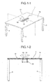
- FIGS. 1-1 and 1-2 a table 10 consisting of a top plate 1 which is a work surface, and a plurality of legs 5 which support the top plate 1.
- the table 10 includes the wiring box 30 having lid bodies 2 which can open and close an opening 3 for wiring (not illustrated), which is formed from the front surface (upper surface) to the rear surface (lower surface) of the top plate 1.
- the lid bodies 2 of the wiring box 30 are configured to cover almost the entire region of the opening 3 formed in the top plate 1, which will be described later, and are further configured so that lid body upper surfaces 2a (lid body surfaces) and a top plate upper surface 1a (top plate surface) form a continuous flat surface. Accordingly, members such as a flange for blocking a gap between the lid body 2 and the top plate 1 are not necessary unlike the prior art, it is possible to remove a height difference formed between the lid body 2 and the top plate surface 1a, and furthermore, it is possible to reduce the gap between the lid body 2 and the opening 3 to be small. Further, there is no intermediate member such as a flange in the periphery of the opening 3, and the opening 3 is covered only by the lid body 2. Therefore, it is possible for the top plate surface 1a to be flat, have good appearance, and thus exhibit high design characteristics.
- the lid bodies 2 in the wiring box 30 of the present invention have a configuration in which the lid bodies 2 are selectively moved between a closed state ( FIG. 2-1 ) in which the opening of the top plate 1 is blocked by the lid bodies 2 and an open state ( FIG. 2-2 ) in which the lid bodies 2 are accommodated inside the opening 3 and the opening 3 for wiring is formed on the top plate.
- gaps formed between the lid bodies 2 and opening edges 4 are small and the lid body surfaces 2a and the top plate surfaces 1a, which will be described later, form a flat surface (uniform surface). Therefore, it is possible to not only enhance the design characteristics of the table 10 but also provide the table 10 with high usability.
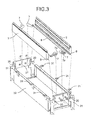
- the wiring box 30 of the present invention includes the left and right lid bodies 2, rotating arms 7 which rotatably support the lid bodies 2, plate-like side covers 21 which rotatably support the rotating arms 7, and a duct 32 which has a U-shaped cross-section and holds the side covers 21.
- the lid body 2 includes a slide pin 9 which protrudes outward from the rear portion of the side surface thereof.
- a bearing (not illustrated) to rotatably support the rotating arms 7 is included inside of the lid body 2.
- the duct 32 is worked by bending a steel plate or the like, and reverse L-shaped mounting metal fittings 31 are welded to the upper end portions of the left and right surfaces thereof in a state of protruding upward.
- the mounting metal fittings 31 are formed to have flat upper end surfaces and have threaded holes formed at substantially the center portions thereof.
- the side covers 21 made of resin are fixed to the front and rear portions of the duct 32 by screws or the like (not illustrated), and the side covers 21 are provided with longitudinal slide grooves 20 with which the slide pins 9 of the lid bodies 2 are engaged and axial holes 6' for rotatably supporting the rotating arms 7.
- the axial holes 6' support one end 7a of the rotating arms 7 to be rotated by shafts 6 and the slide pins 9 of the lid bodies 2 which protrude in the horizontal direction are engaged with the slide grooves 20. Accordingly, the lid bodies 2 are moved up and down along with the rotation of the rotating arms 7 and the slide pins 9 of the lid bodies 2 are able to slide along the slide grooves 20.
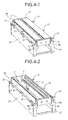
- the left and right lid bodies 2 are held in a state of being parallel and come into close contact with each other at the upper portion of the wiring box 30, and at the time of opening the lid bodies 2, as illustrated in FIG. 4-2 , the left and right lid bodies 2 are accommodated in the wiring box 30 while being held in substantially vertical states.
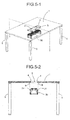
- the top plate 1 has the rectangular opening 3 formed at substantially the center of the top plate 1 from the front surface of the top plate 1 to the rear surface thereof.
- a plurality of convex mounting holes B are formed at the rear surface of the top plate 1 and in the periphery of the opening 3, and the dimensions of the plurality of mounting holes B in the height direction between the upper surfaces of the mounting holes B and the top plate surface 1a are accurately determined.
- the width of the opening 3 and the width of the lid bodies 2 are substantially the same, and thus gaps ⁇ between the opening edges 4 of the top plate 1 and the lid bodies 2 are less likely to be generated.
- the wiring box 30 of the present invention as illustrated in FIGS. 7-1 and 7-2 , a flat and uniform surface without a height difference between the lid bodies 2 of the wiring box 30 and the top plate surface 1a of the table is formed, and positioning and mounting of the wiring box 30 can be simply and accurately performed in the state where gaps between the lid bodies 2 and the opening edges 4 are less likely to be generated.
- screw receivers 90 are provided in the mounting holes B of the top plate 1, and thus the mounting metal fittings 31 of the wiring box 30 can be simply screwed to the screw receivers 90 in a state of being inserted through the mounting holes B.
- the wiring box 30 can be fixed while being accurately positioned.
- a wiring box according to the prior art has a structure in which a unit having a flange part and a mechanism of a lid body integrated in one body is fallen from the above of the top plate and has a separate body structure in which a duct part that receives wires is mounted from the lower side of a top plate.
- the wiring box 30 of the present invention has a structure with no flange part and is in a state where the opening parts of the top plate 1 are completed, and a simple configuration in which the wiring box 30 is inserted into the opening 3 from the lower side of the top plate 1 and the plurality of mounting metal fittings 31 of the wiring box 30 may only be inserted and mounted into the mounting holes B at the lower surface of the top plate is achieved.
- the duct 32 which receives wires has a structure integrated with the lid bodies 2 in one body, and thus there is an effect of significantly reducing the number of components and the number of mounting operations.
- the smallest thickness is postulated as a top plate thickness in advance, and in a case where the top plate thickness is a thickness of 20 mm, the mounting metal fittings 31 are configured to enable the lid bodies 2 and the top plate 1 to form a uniform surface at a thickness of 20 mm.
- the top plate 1 having a thickness of 20 mm or greater a simple configuration in which a thickness of 20 mm from the top plate surface 1a is left and the mounting holes B are formed at the lower surface of the top plate 1 is employed. Accordingly, it is possible to simply mount the wiring box 30 in the state where the lid body surface 2a and the top plate surface 1a are flush with each other.
- the movement of the lid bodies 2 in the wiring box 30 of the present invention is the opening and closing mechanism of opening and closing the opening 3 of the top plate 1 by elevating the lid bodies 2 inside the opening of the top plate 1 and rotating the lid bodies 2 at the surface of the opening of the top plate 1.
- the rear portions of the lid bodies 2 are rotatably supported by the other ends 7b of the rotating arms 7 of which one ends 7a are rotatably supported by the side cover 21 of the wiring box 30, and further, the slide pins 9 protruding from the rear portions of the lid bodies 2 are movably linked to the slide grooves 20 formed in the side cover 21. Accordingly, the lid bodies 2 are elevated by the rotation of the rotating arms 7 while being held in the substantially vertical state, and the lid bodies 2 are rotated in a direction to close the opening in the vicinity of the opening of the top plate 1 so that the lid bodies 2 close the opening 3 of the top plate 1.
- the slide pins 9 provided at the rear portions of the lid bodies 2 move along the slide grooves 20 while meshing with the slide grooves 20 formed in the side cover 21 of the wiring box 30, and thus the movement of the rear end parts of the lid bodies 2 is regulated by the positions of the rotating arms 7.
- the slide groove 20 is the slide groove 20 in which a vertical slide groove, which holds the lid body 2 in the substantially vertical state as the lid body 2 is elevated, and an outwardly curved slide groove, which guides the lid body 2 to be rotated in the vicinity of the surface of the opening of the top plate 1, are continuously arranged.
- the path of the rear portion of the lid body 2 draws a path (the arrow R in the figure) which is vertically elevated inside the opening and a path (the arrow Q in the figure) in which the lid body 2 is rotated in a direction to close the opening in the vicinity of the surface of the opening.
- the path drawn by the lid body 2 is not arc but is a substantially right-angled path made by a combination of the vertical direction and the rotational direction, and thus the path of the lid body 2 is always positioned on the inside of the opening 3. Therefore, the rear portion of the lid body 2 does not protrude outward from the opening edge 4 of the top plate 1. Accordingly, there is no need to additionally provide a space along the arc path of the lid body according to the prior art, and there is no need to provide a member such as a flange between the lid body 2 and the opening 3.
- the lid bodies 2 are in a state of being accumulated inside the opening of the top plate 1, and particularly, in a state where the lid bodies 2 are accommodated while being vertically held and only the tip end portions of the lid bodies 2 are slightly exposed from the surface of the opening of the top plate 1 on the upper side.
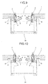
- the tip end portions of the lid bodies 2 are grabbed and pulled upward so that the lid bodies 2 start being elevated by the rotation of the rotating arms 7 as illustrated in FIG. 10 .
- the rotating arms 7 are rotated in the upward direction about the shafts 6 as the fulcrums and the lid bodies 2 are lifted in the vertical state so that the slide pins 9 of the rear portions of the lid bodies 2 slide along the slide grooves 20.
- the slide pins 9 of the lid bodies 2 that slide along the slide grooves 20 and shafts 8 of the rotating arms 7 which rotatably support the lid bodies 2 are positioned to be on a vertical extension line, and even when the rotating arms 7 are rotated, the lid bodies 2 are lifted while being vertically held.
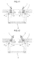
- the lid bodies 2 are lifted upward as illustrated in FIG. 11 , and the slide pins 9 of the lid bodies 2 are lifted along the slide grooves 20.
- the slide pins 9 of the lid bodies 2 and the shafts 8 of the rotating arms 7 are held in the substantially vertical state, and the lid bodies 2 are lifted inside the opening while still maintaining the vertically upright state.
- the lid bodies 2 are lifted upward as illustrated in FIG. 12 , and the slide pins 9 of the lid bodies 2 are lifted along the slide grooves 20.
- the shape of the slide groove 20 with which the slide pin 9 of the lid body 2 meshes is changed from the vertical shape to the outwardly curved shape, and the positional relation between the shaft 8 of the rotating arm 7 and the slide pin 9 of the lid body 2 starts changing.
- the slide pin 9 of the lid body 2 is further moved outward along the arc slide groove 20 and the rotating arm 7 is slightly rotated to return so as to lift the rear portion of the lid body 2 so that the lid bodies 2 are rotated in the direction to close the opening.
- the lid bodies 2 are rotatably supported by the other ends 7b of the rotating arms 7 of which one ends 7a are rotatably supported inside the opening, the lid bodies 2 are elevated while being held in the substantially vertical state inside the opening of the top plate 1 by the rotation of the rotating arms 7, and the opening 3 is closed by the rotation of the lid bodies 2 at the surface of the opening of the top plate 1 so that the top plate surface 1a and the lid body surface 2a form a uniform surface. Therefore, it is possible to provide the wiring box 30 which enables the lid bodies 2 of the wiring box 30 and the top plate 1 to form a flat and uniform surface by the simple configuration at the time of opening the opening of the top plate.
- the slide pins 9 are provided in the lid bodies 2 and the slide grooves 20 which are linked to the slide pins 9 are provided in the wiring box 30.
- the slide groove 20 is a groove in which the slide groove 20, which holds the lid body 2 in the substantially vertical state as the lid body 2 is elevated, and the slide groove 20, which guides the lid body 2 to be rotated at the opening surface 1, are continuously formed. Therefore, the path drawn by the lid body 2 is not arc but is a substantially right-angled path made by a combination of the vertical direction and the rotational direction. Accordingly, the path of the lid body 2 is always positioned on the inside of the opening 3, and thus the rear portion of the lid body 2 does not protrude outward from the opening edge 4 of the top plate 1. Therefore, there is no need to additionally provide a space along the arc path of the lid body according to the prior art, and there is no need to provide a member such as a flange between the lid body 2 and the opening 3.
- the plurality of mounting holes B are provided in the periphery of the opening 3 at the lower surface of the top plate 1
- the plurality of mounting metal fittings 31 are provided in the periphery of the wiring box 30, and the height from the lid body upper surface 2a to the mounting metal fitting 31 and the height from the top plate surface 1a to the mounting hole B are substantially the same. Therefore, when the wiring box 30 is mounted from below the opening 3, the top plate surface 1a and the lid body surface 2a form a uniform surface.
- the wiring box 30 can be mounted from below the top plate 1 without providing a protruding member such as a flange at the upper portion of the wiring box 30.
- the wiring box 30 can be mounted so that the top plate surface 1a and the lid body surface 2a form a uniform surface without changing the height of the mounting metal fittings 31 of the wiring box 30.
- the present invention is not limited thereto, and for example, a single lid body may be employed to exhibit the same effect.
- the example in which the left and right lid bodies 2 are simultaneously moved is described.
- the left and right lid bodies 2 may also be separately moved. In either case, it is natural that the present invention is not limited to the above-described embodiments and can be embodied more effectively by appropriately adding other elements.
Landscapes
- Engineering & Computer Science (AREA)
- Architecture (AREA)
- Civil Engineering (AREA)
- Structural Engineering (AREA)
- Tables And Desks Characterized By Structural Shape (AREA)
- Connection Or Junction Boxes (AREA)
- Installation Of Indoor Wiring (AREA)
- Combinations Of Kitchen Furniture (AREA)
- Casings For Electric Apparatus (AREA)
Applications Claiming Priority (2)
| Application Number | Priority Date | Filing Date | Title |
|---|---|---|---|
| JP2011046620A JP5771415B2 (ja) | 2011-03-03 | 2011-03-03 | 配線ボックスおよびその取付方法 |
| PCT/JP2011/076784 WO2012117625A1 (fr) | 2011-03-03 | 2011-11-21 | Boîte de câblage et procédé pour son installation |
Publications (2)
| Publication Number | Publication Date |
|---|---|
| EP2685577A1 true EP2685577A1 (fr) | 2014-01-15 |
| EP2685577A4 EP2685577A4 (fr) | 2015-04-01 |
Family
ID=46757573
Family Applications (1)
| Application Number | Title | Priority Date | Filing Date |
|---|---|---|---|
| EP11859962.0A Withdrawn EP2685577A4 (fr) | 2011-03-03 | 2011-11-21 | Boîte de câblage et procédé pour son installation |
Country Status (5)
| Country | Link |
|---|---|
| US (1) | US8770420B2 (fr) |
| EP (1) | EP2685577A4 (fr) |
| JP (1) | JP5771415B2 (fr) |
| CN (1) | CN103403988B (fr) |
| WO (1) | WO2012117625A1 (fr) |
Cited By (1)
| Publication number | Priority date | Publication date | Assignee | Title |
|---|---|---|---|---|
| WO2015140418A1 (fr) * | 2014-03-20 | 2015-09-24 | Steelcase Sa | Dispositif pour la fixation d'un cadre dans un orifice traversant d'un panneau |
Families Citing this family (15)
| Publication number | Priority date | Publication date | Assignee | Title |
|---|---|---|---|---|
| JP6098127B2 (ja) * | 2012-11-14 | 2017-03-22 | 株式会社イトーキ | 配線機能付きテーブル |
| JP6219678B2 (ja) * | 2013-10-31 | 2017-10-25 | コクヨ株式会社 | ダクトカバー取付構造およびデスク |
| BR302014001792S1 (pt) * | 2013-11-06 | 2015-06-16 | Samsung Electronics Co Ltd | Configuração aplicada em estande |
| US9800037B2 (en) * | 2015-03-04 | 2017-10-24 | Ditto Sales Inc./Versteel | Power/data access module |
| JP6714345B2 (ja) * | 2015-11-06 | 2020-06-24 | 株式会社オカムラ | テーブル |
| JP6837832B2 (ja) * | 2016-12-27 | 2021-03-03 | コクヨ株式会社 | 天板付家具 |
| JP7021492B2 (ja) * | 2017-09-29 | 2022-02-17 | コクヨ株式会社 | コンセント装置 |
| JP6975612B2 (ja) * | 2017-10-24 | 2021-12-01 | 株式会社イトーキ | 昇降天板付きデスク |
| JP6973706B2 (ja) * | 2017-11-02 | 2021-12-01 | 株式会社内田洋行 | カバー開閉装置 |
| USD858452S1 (en) * | 2018-02-12 | 2019-09-03 | Crestron Electronics, Inc. | Tabletop media center |
| USD863225S1 (en) * | 2018-02-12 | 2019-10-15 | Crestron Electronics, Inc. | Tabletop media center with an interchangeable module |
| IT201800010386A1 (it) * | 2018-11-16 | 2020-05-16 | Knoll Int S P A | Un elemento di arredamento presentante un piano di lavoro, comprendente almeno una apertura passante, ed almeno una porta mobile di chiusura/apertura di detta apertura |
| US10779640B2 (en) | 2018-11-26 | 2020-09-22 | Steelcase Inc. | Cantilevered desk and components and method for the use thereof |
| CN112167839B (zh) * | 2020-06-29 | 2022-08-12 | 杭州嘉裕信息科技有限公司 | 一种基于公共环境卫生的具有自净化功能的收纳装置 |
| CN113576161B (zh) * | 2021-08-02 | 2022-05-27 | 安徽文香科技有限公司 | 一种线路端口安装壳体及具有其的智慧讲桌 |
Family Cites Families (9)
| Publication number | Priority date | Publication date | Assignee | Title |
|---|---|---|---|---|
| US376819A (en) * | 1888-01-24 | Medicinal vapors | ||
| JP2001161449A (ja) | 1999-12-03 | 2001-06-19 | Kokuyo Co Ltd | 収納ボックス |
| JP3503689B2 (ja) * | 1999-12-28 | 2004-03-08 | エビスヤ工業株式会社 | 折畳みテーブル |
| JP4242594B2 (ja) * | 2002-02-15 | 2009-03-25 | 株式会社イトーキ | 多人数用テーブルの配線ダクトにおけるカバー装置 |
| JP4639778B2 (ja) * | 2004-11-30 | 2011-02-23 | 株式会社イトーキ | 机天板等における配線カバー装置 |
| JP5514398B2 (ja) * | 2007-10-19 | 2014-06-04 | 株式会社イトーキ | 配線カバー装置 |
| JP5096981B2 (ja) | 2008-03-31 | 2012-12-12 | 株式会社イトーキ | 嵌め込み式補助装置及びこれを使用したテーブル |
| JP5232598B2 (ja) * | 2008-10-28 | 2013-07-10 | 株式会社岡村製作所 | テーブル |
| JP5289014B2 (ja) | 2008-11-28 | 2013-09-11 | 株式会社イトーキ | 配線カバーの枠構造 |
-
2011
- 2011-03-03 JP JP2011046620A patent/JP5771415B2/ja active Active
- 2011-11-21 CN CN201180068830.2A patent/CN103403988B/zh not_active Expired - Fee Related
- 2011-11-21 EP EP11859962.0A patent/EP2685577A4/fr not_active Withdrawn
- 2011-11-21 WO PCT/JP2011/076784 patent/WO2012117625A1/fr not_active Ceased
- 2011-11-21 US US14/002,485 patent/US8770420B2/en not_active Expired - Fee Related
Cited By (2)
| Publication number | Priority date | Publication date | Assignee | Title |
|---|---|---|---|---|
| WO2015140418A1 (fr) * | 2014-03-20 | 2015-09-24 | Steelcase Sa | Dispositif pour la fixation d'un cadre dans un orifice traversant d'un panneau |
| US10201224B2 (en) | 2014-03-20 | 2019-02-12 | Steelcase Inc. | Device for fixing a frame in a through-orifice in a panel |
Also Published As
| Publication number | Publication date |
|---|---|
| US20130334219A1 (en) | 2013-12-19 |
| WO2012117625A1 (fr) | 2012-09-07 |
| CN103403988A (zh) | 2013-11-20 |
| US8770420B2 (en) | 2014-07-08 |
| JP2012186883A (ja) | 2012-09-27 |
| EP2685577A4 (fr) | 2015-04-01 |
| CN103403988B (zh) | 2017-05-03 |
| JP5771415B2 (ja) | 2015-08-26 |
Similar Documents
| Publication | Publication Date | Title |
|---|---|---|
| US8770420B2 (en) | Wiring box and method of mounting the same | |
| KR101157801B1 (ko) | 도어 힌지 | |
| CN103128733B (zh) | 伸缩竖梁装置 | |
| US20160299538A1 (en) | Double-track guided hinge | |
| CN113114828B (zh) | 电子设备 | |
| EP2610000A1 (fr) | Structure à trois portes adaptée à un malaxeur de solution de couchage du type à rotation autour de deux axes | |
| AT509028A1 (de) | Ladestation für ein elektronisches gerät | |
| CN108402676A (zh) | 一种旋转隐藏式电脑桌 | |
| KR20170078984A (ko) | 디스플레이 장치 | |
| CN210965731U (zh) | 一种基于pcb板生产的全自动点胶机 | |
| WO2014178534A1 (fr) | Dispositif coulissant destiné à la protection d'un agencement de câbles de bureau | |
| KR200442673Y1 (ko) | 다기능 공작기기용 공구 걸이대 | |
| JP6210072B2 (ja) | 音響調整コンソール | |
| CN116111476A (zh) | 一种空间可调式配电柜及其安装结构 | |
| JP6888773B1 (ja) | キャビネットおよび姿勢切替装置 | |
| US9872420B1 (en) | Shielding box for providing high frequency electromagnetic shielding | |
| EP2143356B1 (fr) | Dispositif de levage d'un écran plat | |
| JP2025029879A (ja) | ラック | |
| CN218351942U (zh) | 一种新型用于现代化工厂的可调式电器柜 | |
| JP4528379B2 (ja) | パチンコ機 | |
| JP2012222135A (ja) | 電気機器収納箱 | |
| JP2013103070A (ja) | 吊り戸棚 | |
| CN220064735U (zh) | 一种理线结构及电子装置 | |
| CN213540057U (zh) | 一种防下垂装置及电气柜 | |
| CN209132775U (zh) | Pcb板入库扫描枪的安装结构 |
Legal Events
| Date | Code | Title | Description |
|---|---|---|---|
| PUAI | Public reference made under article 153(3) epc to a published international application that has entered the european phase |
Free format text: ORIGINAL CODE: 0009012 |
|
| 17P | Request for examination filed |
Effective date: 20130830 |
|
| AK | Designated contracting states |
Kind code of ref document: A1 Designated state(s): AL AT BE BG CH CY CZ DE DK EE ES FI FR GB GR HR HU IE IS IT LI LT LU LV MC MK MT NL NO PL PT RO RS SE SI SK SM TR |
|
| DAX | Request for extension of the european patent (deleted) | ||
| A4 | Supplementary search report drawn up and despatched |
Effective date: 20150226 |
|
| RIC1 | Information provided on ipc code assigned before grant |
Ipc: A47B 13/00 20060101ALI20150220BHEP Ipc: H02G 3/12 20060101ALI20150220BHEP Ipc: H02G 3/38 20060101AFI20150220BHEP |
|
| 17Q | First examination report despatched |
Effective date: 20160113 |
|
| GRAP | Despatch of communication of intention to grant a patent |
Free format text: ORIGINAL CODE: EPIDOSNIGR1 |
|
| GRAJ | Information related to disapproval of communication of intention to grant by the applicant or resumption of examination proceedings by the epo deleted |
Free format text: ORIGINAL CODE: EPIDOSDIGR1 |
|
| GRAP | Despatch of communication of intention to grant a patent |
Free format text: ORIGINAL CODE: EPIDOSNIGR1 |
|
| GRAJ | Information related to disapproval of communication of intention to grant by the applicant or resumption of examination proceedings by the epo deleted |
Free format text: ORIGINAL CODE: EPIDOSDIGR1 |
|
| GRAP | Despatch of communication of intention to grant a patent |
Free format text: ORIGINAL CODE: EPIDOSNIGR1 |
|
| INTG | Intention to grant announced |
Effective date: 20161110 |
|
| INTG | Intention to grant announced |
Effective date: 20161121 |
|
| INTG | Intention to grant announced |
Effective date: 20161129 |
|
| STAA | Information on the status of an ep patent application or granted ep patent |
Free format text: STATUS: THE APPLICATION IS DEEMED TO BE WITHDRAWN |
|
| 18D | Application deemed to be withdrawn |
Effective date: 20170411 |