EP2685609B1 - Dispositif d'entraînement pour véhicule électrique - Google Patents
Dispositif d'entraînement pour véhicule électrique Download PDFInfo
- Publication number
- EP2685609B1 EP2685609B1 EP11860425.5A EP11860425A EP2685609B1 EP 2685609 B1 EP2685609 B1 EP 2685609B1 EP 11860425 A EP11860425 A EP 11860425A EP 2685609 B1 EP2685609 B1 EP 2685609B1
- Authority
- EP
- European Patent Office
- Prior art keywords
- speed reduction
- input shaft
- reduction unit
- bearings
- drive device
- Prior art date
- Legal status (The legal status is an assumption and is not a legal conclusion. Google has not performed a legal analysis and makes no representation as to the accuracy of the status listed.)
- Not-in-force
Links
- 238000005096 rolling process Methods 0.000 claims description 20
- 239000000725 suspension Substances 0.000 claims description 16
- 125000006850 spacer group Chemical group 0.000 claims description 10
- 238000005192 partition Methods 0.000 description 29
- 230000004308 accommodation Effects 0.000 description 16
- 238000003780 insertion Methods 0.000 description 9
- 230000037431 insertion Effects 0.000 description 9
- WABPQHHGFIMREM-UHFFFAOYSA-N lead(0) Chemical compound [Pb] WABPQHHGFIMREM-UHFFFAOYSA-N 0.000 description 8
- 239000000314 lubricant Substances 0.000 description 8
- 230000002093 peripheral effect Effects 0.000 description 4
- 239000003638 chemical reducing agent Substances 0.000 description 3
- 230000000694 effects Effects 0.000 description 3
- 239000000945 filler Substances 0.000 description 3
- 230000004323 axial length Effects 0.000 description 2
- 230000000903 blocking effect Effects 0.000 description 2
- 238000002485 combustion reaction Methods 0.000 description 1
- 230000007423 decrease Effects 0.000 description 1
- 230000006866 deterioration Effects 0.000 description 1
- 230000017525 heat dissipation Effects 0.000 description 1
- 230000007257 malfunction Effects 0.000 description 1
- 239000002184 metal Substances 0.000 description 1
- 238000004804 winding Methods 0.000 description 1
Images



Classifications
-
- H—ELECTRICITY
- H02—GENERATION; CONVERSION OR DISTRIBUTION OF ELECTRIC POWER
- H02K—DYNAMO-ELECTRIC MACHINES
- H02K7/00—Arrangements for handling mechanical energy structurally associated with dynamo-electric machines, e.g. structural association with mechanical driving motors or auxiliary dynamo-electric machines
- H02K7/10—Structural association with clutches, brakes, gears, pulleys or mechanical starters
- H02K7/116—Structural association with clutches, brakes, gears, pulleys or mechanical starters with gears
-
- B—PERFORMING OPERATIONS; TRANSPORTING
- B60—VEHICLES IN GENERAL
- B60K—ARRANGEMENT OR MOUNTING OF PROPULSION UNITS OR OF TRANSMISSIONS IN VEHICLES; ARRANGEMENT OR MOUNTING OF PLURAL DIVERSE PRIME-MOVERS IN VEHICLES; AUXILIARY DRIVES FOR VEHICLES; INSTRUMENTATION OR DASHBOARDS FOR VEHICLES; ARRANGEMENTS IN CONNECTION WITH COOLING, AIR INTAKE, GAS EXHAUST OR FUEL SUPPLY OF PROPULSION UNITS IN VEHICLES
- B60K17/00—Arrangement or mounting of transmissions in vehicles
- B60K17/04—Arrangement or mounting of transmissions in vehicles characterised by arrangement, location or kind of gearing
- B60K17/043—Transmission unit disposed in on near the vehicle wheel, or between the differential gear unit and the wheel
- B60K17/046—Transmission unit disposed in on near the vehicle wheel, or between the differential gear unit and the wheel with planetary gearing having orbital motion
-
- B—PERFORMING OPERATIONS; TRANSPORTING
- B60—VEHICLES IN GENERAL
- B60K—ARRANGEMENT OR MOUNTING OF PROPULSION UNITS OR OF TRANSMISSIONS IN VEHICLES; ARRANGEMENT OR MOUNTING OF PLURAL DIVERSE PRIME-MOVERS IN VEHICLES; AUXILIARY DRIVES FOR VEHICLES; INSTRUMENTATION OR DASHBOARDS FOR VEHICLES; ARRANGEMENTS IN CONNECTION WITH COOLING, AIR INTAKE, GAS EXHAUST OR FUEL SUPPLY OF PROPULSION UNITS IN VEHICLES
- B60K7/00—Disposition of motor in, or adjacent to, traction wheel
- B60K7/0007—Disposition of motor in, or adjacent to, traction wheel the motor being electric
-
- H—ELECTRICITY
- H02—GENERATION; CONVERSION OR DISTRIBUTION OF ELECTRIC POWER
- H02K—DYNAMO-ELECTRIC MACHINES
- H02K11/00—Structural association of dynamo-electric machines with electric components or with devices for shielding, monitoring or protection
- H02K11/20—Structural association of dynamo-electric machines with electric components or with devices for shielding, monitoring or protection for measuring, monitoring, testing, protecting or switching
- H02K11/21—Devices for sensing speed or position, or actuated thereby
- H02K11/225—Detecting coils
-
- H—ELECTRICITY
- H02—GENERATION; CONVERSION OR DISTRIBUTION OF ELECTRIC POWER
- H02K—DYNAMO-ELECTRIC MACHINES
- H02K5/00—Casings; Enclosures; Supports
- H02K5/04—Casings or enclosures characterised by the shape, form or construction thereof
- H02K5/16—Means for supporting bearings, e.g. insulating supports or means for fitting bearings in the bearing-shields
- H02K5/173—Means for supporting bearings, e.g. insulating supports or means for fitting bearings in the bearing-shields using bearings with rolling contact, e.g. ball bearings
- H02K5/1732—Means for supporting bearings, e.g. insulating supports or means for fitting bearings in the bearing-shields using bearings with rolling contact, e.g. ball bearings radially supporting the rotary shaft at both ends of the rotor
-
- H—ELECTRICITY
- H02—GENERATION; CONVERSION OR DISTRIBUTION OF ELECTRIC POWER
- H02K—DYNAMO-ELECTRIC MACHINES
- H02K7/00—Arrangements for handling mechanical energy structurally associated with dynamo-electric machines, e.g. structural association with mechanical driving motors or auxiliary dynamo-electric machines
- H02K7/08—Structural association with bearings
- H02K7/083—Structural association with bearings radially supporting the rotary shaft at both ends of the rotor
-
- B—PERFORMING OPERATIONS; TRANSPORTING
- B60—VEHICLES IN GENERAL
- B60K—ARRANGEMENT OR MOUNTING OF PROPULSION UNITS OR OF TRANSMISSIONS IN VEHICLES; ARRANGEMENT OR MOUNTING OF PLURAL DIVERSE PRIME-MOVERS IN VEHICLES; AUXILIARY DRIVES FOR VEHICLES; INSTRUMENTATION OR DASHBOARDS FOR VEHICLES; ARRANGEMENTS IN CONNECTION WITH COOLING, AIR INTAKE, GAS EXHAUST OR FUEL SUPPLY OF PROPULSION UNITS IN VEHICLES
- B60K7/00—Disposition of motor in, or adjacent to, traction wheel
- B60K2007/0038—Disposition of motor in, or adjacent to, traction wheel the motor moving together with the wheel axle
-
- B—PERFORMING OPERATIONS; TRANSPORTING
- B60—VEHICLES IN GENERAL
- B60K—ARRANGEMENT OR MOUNTING OF PROPULSION UNITS OR OF TRANSMISSIONS IN VEHICLES; ARRANGEMENT OR MOUNTING OF PLURAL DIVERSE PRIME-MOVERS IN VEHICLES; AUXILIARY DRIVES FOR VEHICLES; INSTRUMENTATION OR DASHBOARDS FOR VEHICLES; ARRANGEMENTS IN CONNECTION WITH COOLING, AIR INTAKE, GAS EXHAUST OR FUEL SUPPLY OF PROPULSION UNITS IN VEHICLES
- B60K7/00—Disposition of motor in, or adjacent to, traction wheel
- B60K2007/0092—Disposition of motor in, or adjacent to, traction wheel the motor axle being coaxial to the wheel axle
-
- H—ELECTRICITY
- H02—GENERATION; CONVERSION OR DISTRIBUTION OF ELECTRIC POWER
- H02K—DYNAMO-ELECTRIC MACHINES
- H02K5/00—Casings; Enclosures; Supports
- H02K5/04—Casings or enclosures characterised by the shape, form or construction thereof
- H02K5/18—Casings or enclosures characterised by the shape, form or construction thereof with ribs or fins for improving heat transfer
-
- H—ELECTRICITY
- H02—GENERATION; CONVERSION OR DISTRIBUTION OF ELECTRIC POWER
- H02K—DYNAMO-ELECTRIC MACHINES
- H02K5/00—Casings; Enclosures; Supports
- H02K5/04—Casings or enclosures characterised by the shape, form or construction thereof
- H02K5/22—Auxiliary parts of casings not covered by groups H02K5/06-H02K5/20, e.g. shaped to form connection boxes or terminal boxes
- H02K5/225—Terminal boxes or connection arrangements
-
- Y—GENERAL TAGGING OF NEW TECHNOLOGICAL DEVELOPMENTS; GENERAL TAGGING OF CROSS-SECTIONAL TECHNOLOGIES SPANNING OVER SEVERAL SECTIONS OF THE IPC; TECHNICAL SUBJECTS COVERED BY FORMER USPC CROSS-REFERENCE ART COLLECTIONS [XRACs] AND DIGESTS
- Y02—TECHNOLOGIES OR APPLICATIONS FOR MITIGATION OR ADAPTATION AGAINST CLIMATE CHANGE
- Y02T—CLIMATE CHANGE MITIGATION TECHNOLOGIES RELATED TO TRANSPORTATION
- Y02T10/00—Road transport of goods or passengers
- Y02T10/60—Other road transportation technologies with climate change mitigation effect
- Y02T10/64—Electric machine technologies in electromobility
Definitions
- the present invention relates to a drive device for an electric vehicle including an electric motor as a drive source, and particularly to a drive device for an electric vehicle of an in-wheel motor type.
- a conventionally known drive device for an electric vehicle of an in-wheel motor type is made up of an electric motor, a speed reduction unit to which the output of the electric motor is inputted, and a hub unit which is rotationally driven by the speed-reduced output of the speed reduction unit (Patent Literature 1).
- a typical configuration of a speed reduction unit of planetary gear type is such that a sun gear is provided on an input shaft in a coaxial manner, and a ring gear is secured around the input shaft in a coaxial manner.
- a plurality of pinion gears are placed between the sun gear and the ring gear, and a pinion pin that supports each pinion gear is joined to a common carrier.
- the carrier is integrated with an output member.
- the speed reduction unit is configured such that the pinion gear is caused to revolve while rotating on its axis by the rotation of the input shaft.
- the rotational speed of the revolving motion is reduced from the rotational speed of the input shaft, and a speed-reduced rotation is transferred to the output member via the carrier.
- the speed reduction ratio in this case will be Zs/(Zs + Zr). Where, Zs is the number of teeth of the sun gear, and Zr is the number of teeth of the ring gear.
- the input shaft of the speed reduction unit is supported by bearings disposed at two locations in the axial direction, that is, an inboard-side bearing and an outboard side bearing.
- the inboard-side bearing is attached to a housing of the speed reduction unit, and the outboard-side bearing is attached to the output member of the speed reduction unit.
- the housing is supported by the vehicle body via the suspension, and the output member is coupled and integrated with an inner member of the hub unit to rotationally drive the vehicle wheel.
- the radial load acting on the input shaft of the speed reduction unit is supported by the housing via the inboard-side bearing on the inboard side, and is supported by the output member of the speed reduction unit via the outboard-side bearing on the outboard side.
- the hub unit is joined to a suspension via a knuckle on the vehicle body side in a normal motor vehicle driven by an internal combustion engine.
- Patent Literature 1 Japanese Patent Laid-Open No. 2001-32888
- the hub and the hub bearings that support the output member of the speed reduction unit elastically deform due to the effect of the load imposed on the vehicle wheel from the road, the outboard-side bearing is displaced with respect to the original center of the input and output shafts.
- the housing that supports the inboard-side bearing is not likely to be affected by the load from the vehicle wheel, and therefore the coaxiality between the two bearings that support the input shaft deteriorates or the inclination therebetween occurs.
- eccentric load is likely to act on the inboard-side bearing and the outboard-side bearing, thus causing problems such as decline of rotational accuracy of the input shaft, deterioration of the durability of the bearings, and occurrence of rotation noise of the bearings.
- the generic document EP 1 932 706 A2 discloses a power-driven wheel for a military vehicle, comprising an electric motor, a reducer including a shaft driven by output of the electric motor, a hub rotationally driven by a main body of planet carrier being part of the reducer, and a casing accommodating the electric motor.
- the shaft of the reducer is supported by bearings provided at two locations in the axial direction. The bearings are both supported by the main body of the planet carrier.
- the housing is provided with a suspension joining portion.
- US 2009/0166111 A1 discloses an in-wheel motor comprising an electric machine accommodated in a housing and a reduction gear.
- the housing includes two support portions provided at two centrosymmetric locations of the housing.
- the present invention provides a drive device for an electric vehicle, comprising: an electric motor; a speed reduction unit including an input shaft driven by output of the electric motor; a hub unit rotationally driven by an output member of the speed reduction unit; and a housing accommodating the electric motor and the speed reduction unit, wherein the input shaft of the speed reduction unit is supported by bearings provided at two locations in the axial direction, the drive device being configured such that the bearings provided at the two locations are both supported by the output member, and the housing is provided with a suspension joining portion.
- the bearings for supporting the input shaft at two locations in the axial direction are attached together to the output member, vibration and impact transmitted from the vehicle wheel to the output member will be imposed on both the bearings at the same time and in the same manner. As a result of this, both the bearings are prevented from being subjected to eccentric load.
- the drive device for an electric vehicle can be attached to the vehicle body by directly joining the above-described suspension joining portion to the vehicle body, and thus a knuckle as an intermediate part is not required.
- the output member may be configured to include flanges disposed on both sides in the axial direction of a speed reduction rotational member such as a pinion gear so that the flanges are coupled and integrated with each other by both end portions of a support pin of the speed reduction rotational member being secured to the flanges, and each of the above-described bearings is placed between the inner radial surface of each flange and the input shaft.
- a speed reduction rotational member such as a pinion gear
- the pinion gear can be placed between both the flanges.
- the flanges can be configured to be coupled with each other by a bridge so that the flanges can be securely coupled and integrated with each other by the bridge.
- both the flanges are securely engaged and integrated with each other by the above-described bridge, the support stiffness of the support pin such as the pinion pin whose both end portions are coupled to both the flanges is increased. Moreover, by providing the bridge at multiple locations of equally spaced positions in a circumferential direction of the flange, the rotation of the output member becomes smooth, and the rotational accuracy of the input shaft and the rotor of the electric motor fitted and secured to the input shaft is improved.
- the present invention is configured such that a pair of bearings supporting an input shaft of a speed reduction unit are both attached to an output member of the speed reduction unit, both the bearings are prevented from being subj ected to eccentric load.
- the present invention can achieve the effects of improving the rotational accuracy of the input shaft and the durability of the bearings, and further suppressing the rotation noise of the bearings.
- the suspension joining portion is provided in the housing, there is no need of providing a knuckle on the vehicle body side, thus allowing reduction of the number of parts on the vehicle body side.
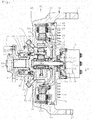
- a drive device for an electric vehicle relating Embodiment 1 includes, as principal components, an electric motor 11, a speed reduction unit 12 which is driven by the output power of the electric motor 11, a hub unit 15 which is rotated by an output member 14 coaxial with an input shaft 13 of the speed reduction unit 12, and a housing 16 which accommodates the electric motor 11 and the speed reduction unit 12, as shown in Fig. 1 .
- the above-described housing 16 includes a cylindrical portion 17 and a front end portion 18 in the radial direction, which is provided at the front end of the cylindrical portion (the end portion of an outboard side, or an end portion on the left side of the figure).
- a central portion of the front end portion 18 is opened, and a rear end portion of an outer member 21 of the hub unit 15 is fitted into an opening hole 19 so that a flange 22 is secured to the front end portion 18 with a bolt 23.
- a partition base portion 18a which is concentric with the opening hole 19 and has a larger diameter than that, is provided inside the front end portion 18 of the housing 16.
- a dish-shaped partition member 20 is secured to the partition base portion 18a with a bolt 20a.
- a center hole 25 is provided at the center of the partition member 20. The center hole 25 faces an outer radial surface of the input shaft 13 with a gap in a radial direction therebetween.
- a partition 24 is formed of the above-described partition base portion 18a and the partition member 20 joined and secured thereto. The partition 24 has a function of sectioning the interior of the housing 16 into an accommodation space for the electric motor 11 on the outer radial side, and an accommodation space for the speed reduction unit 12 on the inner radial side.
- a suspension joining portion 27 which projects in the axial direction is provided at two centrosymmetric locations on a rear end edge of the cylindrical portion 17 of the housing 16.
- the hub unit 15 is joined to the suspension with a knuckle of the vehicle body lying therebetween; however, in the present Embodiment 1, the suspension on the vehicle body side can be directly joined to the suspension joining portion 27 which is a part of the housing 16.
- the housing 16 Since the housing 16 will achieve the function of the knuckle, it can be described as a structure in which the knuckle is integrated with the housing 16. In this case, if the outer member 21 of the hub unit 15 becomes necessary to be replaced, the replacement can be performed simply by detaching the bolt 23 without need of detaching the housing 16 from the suspension.
- the electric motor 11 is a radial-gap-type brushless DC motor, and is made up of a stator 28 secured to an inner radial surface of the cylindrical portion 17 of the housing 16, and a rotor 29 disposed on an inner radial surface of the stator 28 with a radial gap.
- the rotor 29 is fitted and secured to the input shaft 13 by a rotor support member 31.
- the rotor support member 31 is made up of a support member cylindrical portion 31a (see Fig. 2 ) fitted to an inner radial portion of the rotor 29, and a support member disc portion 31b which extends reward along the partition 24 and which is bent to the inner radial direction of the partition.
- a boss portion 31c is provided in an inner radial portion of the support member disc portion 31b, and the boss portion 31c is fitted to the input shaft 13 and secured to the input shaft 13 with a key locking portion 35.
- the above-described boss portion 31c is inserted into the inner radial side of the center hole 25 of the partition 24, and an oil seal member 36 is placed between the center hole 25 and the boss portion 31c (see Fig. 2 ).
- the accommodation portion of the electric motor 11 and the accommodation portion of the speed reduction unit 12 are partitioned and oil-sealed by the partition 24 and the oil seal member 36.
- lubricant oil on the speed reduction unit 12 side is prevented from moving to the electric motor 11 side, and thus the electric motor 11 side is kept dry, thus resolving the malfunction that the lubricant oil hinders the rotation of the rotor 29.
- the speed reduction unit 12 is of a planetary gear type, and is made up of, as shown in Fig. 2 , the input shaft 13, the output member 14, a sun gear 39 which is attached to the outer radial surface of the input shaft with a key locking portion 38, a ring gear 42 which is disposed along an inner radial surface of a partition cylindrical portion 24b in the outer periphery of the sun gear 39, and which is attached with a key locking portion 41, and pinion gears 43 which are disposed at three locations equally spaced in the circumferential direction between the ring gear 42 and the sun gear 39.
- the pinion gear 43 is supported by a pinion pin 45 via a needle roller bearing 44.
- the output member 14 includes a coupled shaft portion 47 at an end portion of an outboard side thereof.
- the coupled shaft portion 47 is spline-coupled to an inner member 46 of the hub unit 15 and secured by a nut 50.
- a bearing support portion 49 which is formed to have a one-step larger diameter than that of the coupled shaft portion 47, is provided on the inner end side of the coupled shaft portion 47.
- a pair of flanges 52 and 53 which oppose each other in the axial direction are provided with a spacing slightly larger than the width of the pinion gear 43 in the axial direction.
- a bridge 54 for joining the flanges 52 and 53 to each other in the axial direction is provided at three locations of equally spaced positions in the circumferential direction.
- the flanges 52 and 53 have a function as a carrier in the speed reduction unit 12 of planetary gear type.
- Providing the bridge 54 at equally spaced positions in the circumferential direction allows the output member 14 to be smoothly rotated, and moreover, to improve the rotational accuracy of the rotor 29 of the electric motor 11 through the output member 14 and the input shaft 13.
- a shaft hole 51 which is coaxial with the coupled shaft portion 47 is provided at the center of an end surface of the flange 53 of the inboard side. This shaft hole 51 has a length reaching the bearing support portion 49.
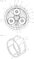
- pinion gear accommodation portions 55 at the three locations, which are sectioned in the circumferential direction by the pair of the flanges 52 and 53 opposing each other in the axial direction, and the bridges 54 at the three locations in the circumferential direction (see Fig. 3 ).
- the pinion gear 43 is accommodated in each pinion gear accommodation portion 55, and both end portions of the pinion pin 45 are inserted through the flanges 52 and 53, respectively, and each secured by a locking screw 56. It can be said that both the flanges 52 and 53 are coupled and integrated with each other not only by the bridge 54, but also by the pinion pin 45.
- a thrust plate 57 is placed between each side surface of each pinion gear 43 and each of the flanges 52 and 53 to ensure smooth rotation of the pinion gear 43.
- a pair of rolling bearings 58 and 59 for supporting the input shaft 13 are provided on both sides of the sun gear 39 between an inner radial surface of each of the flanges 52 and 53 and the outer radial surface of the input shaft 13 opposing each of the inner radial surfaces of the flanges 52 and 53.
- the respective rolling bearings 58 and 59 are supported together by the same output member 14.
- the positional relationship in the axial direction between each of the rolling bearings 58 and 59, and a fitting portion between the support member disc portion 31b and the input shaft 13 is such that the respective rolling bearings 58 and 59 are disposed together on the outboard side, and form a so-called cantilever support structure as the support structure for the input shaft 13.
- Patent Literature 1 While the bearing on the outboard side is disposed on the outboard side with respect to the fitting portion between the support member disc portion and the input shaft, the bearing on the inboard side is attached to the housing, and therefore is located on the inboard side with respect to the above-described fitting portion. Therefore, the support structure of the input shaft forms a so-called both-end support structure.
- the cantilever support structure is characterized by a simplified structure compared with the both-end support structure.
- the above-described rolling bearing 58 on the outboard side is configured such that its inner ring is engaged with a stepped portion 61 provided in the input shaft 13, and its outer ring is engaged with a stepped portion 62 provided in an inner radial surface of the shaft hole 51.
- the rolling bearing 59 on the inboard side is configured such that its inner ring is engaged with the boss portion 31c of the rotor support member 31 and the key locking portion 35, and its outer ring is engaged with a retaining ring 63.
- the sun gear 39 is placed between the respective inner rings of the respective rolling bearings 58 and 59, and also a spacer 64 is placed between the outer rings.
- the spacer 64 prevents both the rolling bearings 58 and 59 from being displaced in a direction to approach to each other.
- the spacer 64 is formed into a cylindrical form as shown in Figs. 3 and 4 , and is provided, at three locations in the circumferential direction, with window holes 65 which correspond to the shape of the above-described pinion gear accommodation portion 55. Further, a closure portion 66 between the respective window holes 65 is formed into a shape corresponding to the shape of the bottom plane of the above-described bridge 54.
- the spacer 64 is placed between the rolling bearings 58 and 59 on the inner radial surface of the shaft hole 51 in a posture that each window hole 65 corresponds to the pinion gear accommodation portion 55 (see Fig. 3 ), and is configured to be positioned by screwing a securing screw 67 from an outer radial surface of the bridge 54 into a positioning hole 60 (see Fig. 4 ).
- the above-described spacer 64 allows to control the bearing pressurization to be applied to both the rolling bearings 58 and 59 by appropriately setting the axial length thereof, thus providing a simple fixed-position pressurization structure.
- the speed reduction unit 12 When seen in the radial direction, the speed reduction unit 12 is radially disposed to be accommodated on the inner radial side of the electric motor 11 with respect to the partition 24, and the size in the axial direction is made compact compared with a case where the unit is disposed in the axial direction.
- the partition cylindrical portion 24b is placed between the electric motor 11 and the speed reduction unit 12, which are disposed in the radial direction, and a partition disc portion 24a is placed between the speed reduction unit 12 and the support member disc portion 31b.
- a peripheral edge portion of the center hole 25 faces the outer radial surface of the boss portion 31c of the rotor support member 31 with a predetermined spacing therebetween.
- the ring gear 42 of the speed reduction unit 12 is secured to an inner radial surface of the partition base portion 18a with the key locking portion 41.
- the oil seal member 36 is placed between the peripheral edge portion of the above-described center hole 25 and the boss portion 31c.
- the accommodation space for the electric motor 11 of the housing 16 and the accommodation space for the speed reduction unit 12 are partitioned by the presence of the oil seal member 36 and the partition 24. Since, as a result of this, the lubricant oil on the speed reduction unit 12 side is prevented from moving to the electric motor 11 side, and thus the electric motor side is kept dry, the lubricant oil is prevented from hindering the rotation of the rotor 29.
- both the flanges 52 and 53 of the output member 14 are coupled and integrated by both the bridge 54 and the pinion pin 45
- the flange 53 is configured to be a separate body from the output member 14 and both are coupled and integrated by the pinion pin 45, as shown in Figs. 6A and 6B .
- An oil filler port 68 and an oil drainage port 69 for lubricant oil to lubricate the interior of the speed reduction unit 12 are provided in the front end portion of the housing 16.
- the lubricant oil is sealed by the above-described oil seal member 36 on the electric motor 11 side, and is sealed by an oil seal member 70, which is placed between the bearing support portion 49 of the output member 14 and the outer member 21, on the hub unit 15 side.
- the oil filler port 68 and the oil drainage port 69 are blocked by a blocking screw 72.
- a rear cover 73 is fitted to the rear end portion of the cylindrical portion 17 via a seal member 60.
- a fin 74 for heat dissipation is provided on an outer side surface of the rear cover 73 so that heat of the electric motor 11 is dissipated to the outside.
- a rotation angle sensor 75 is provided between the center hole of the rear cover 73 and the input shaft 13 that passes through the center hole, and that portion is covered by a sensor cover 77.
- the rotation angle sensor 75 shown is a resolver, and whose sensor stator 75a is secured into the center hole of the rear cover 73, and a sensor rotor 75b is attached to the input shaft 13.
- a lead wire 83 of the sensor stator 75a is connected to a connector insertion portion 78 provided outside the sensor cover 77.
- a Hall element can be used besides the above-described resolver.
- a rotational angle of the input shaft 13 detected by the rotation angle sensor 75 is inputted to a control circuit, which is omitted from showing, via the above-described signal wire cable to be used for the rotational control of the electric motor 11.
- a power supply terminal box 76 for providing power supply to the stator 28 of the electric motor 11 is provided at a position decentered toward an outer peripheral edge of the above-described rear cover 73, and at a position 90 degrees different from the above-described suspension joining portion 27 (see Fig. 5 ).
- the power supply terminal box 76 is formed into a cylindrical shape that passes through the rear cover 73, and is provided with a working hole 80 in an outer peripheral portion of the box.
- the working hole 80 is usually blocked by a cover 81.
- a power supply terminal 82 is provided inside the box at a position opposing the working hole 80.
- a lead wire 83 connected to the winding of the stator 28 is connected to the power supply terminal 82, and also a connection terminal of a power supply cable 84 is connected to the same power supply terminal 82. These are secured by fastening screws 85.
- a cable hole 84a is provided at a rear end of the power supply terminal box 76 and the power supply cable 84 is inserted therethrough.
- the hub unit 15 is made up of, as shown in Fig. 1 , the above-described inner member 46 which is integrated with a hub 86, a pair of inner rings 87 that are fitted to an outer radial surface of the inner member 46, the outer member 21 having the flange 22, an outer ring 88 fitted to an inner radial surface of the outer member 21 and having multiple rows of tracks, and multiple rows of balls 89 to be placed between the inner ring 87 and the outer ring 88.
- the vehicle wheel is attached to the hub 86 with hub bolts 90.
- the coupled shaft portion 47 of the output member 14 is spline-coupled to an inner radial surface of the inner member 46, and a tip end portion of the coupled shaft portion 47 projecting to the outside from the inner member 46 is secured by the nut 50 as described above.
- securing means such as press cut joint, diameter expansion caulking, and swing caulking may be adopted.
- hub unit 15 is of a form of so-called first generation, those of a form of the second generation or third generation may be used.
- the driving device for an electric vehicle of Embodiment 1 is configured as described above, and next, the operation thereof will be described.
- the input shaft 13 is rotated integrally with the rotation of the rotor 29, and a motor output is inputted to the speed reduction unit 12.
- the speed reduction unit 12 when the sun gear 39 rotates integrally with the input shaft 13, the pinion gears 43 revolve around the sun gear 39 while rotating on their own axes.
- Each of the pinion pins 45 performs speed-reduced rotation at its revolving speed, and thereby rotates the output member 14 at a speed-reduced output shown by the above-described speed reduction ratio.
- the inner member 46 of the hub unit 15 is rotated integrally with the coupled shaft portion 47 of the output member 14, thereby driving the wheel attached to the hub 86.
- the above-described input shaft 13 rotates by being supported respectively by the rolling bearing 58 on the outboard side and the rolling bearing 59 on the inboard side at both sides of the pinion gear 43. Since these rolling bearings 58 and 59 are both attached to the respective flanges 52 and 53 (respective flanges 52 and 53 which are integrated via the pinion pin 45 in the case of Figs. 6A and 6B ) which are each integrated with the output member 14, vibration and impact in the radial direction which are transmitted from the wheel to the output member 14 through the hub unit 15 is imposed onto both the rolling bearings 58 and 59 at the same time and in the same manner.
- both the rolling bearings 58 and 59 can be prevented from being subjected to eccentric load, it is possible to improve the rotational accuracy and durability, and suppress the rotation noise.
- the above-described rolling bearings 58 and 59 are disposed on the outboard side with respect to the fitting portion between the rotor support member 31 of the rotor 29 and the input shaft 13, that is, the key locking portion 35, so that the support structure becomes simple and easy to be assembled compared with a conventional case where the bearings are disposed on both sides thereof.
- the lubricant oil in the speed reduction unit 12 is sealed on the electric motor 11 side by the oil seal member 36, and sealed on the hub unit 15 side by the oil seal member 70, leakage on the electric motor 11 side and the hub unit side is prevented. As a result of that, on the electric motor 11 side, rotation of the rotor 29 is not hindered, and on the hub unit 15 side, leakage of the lubricant oil to the outside through the hub unit 15 is prevented.
- the heat generated in association with the driving of the electric motor 11 is effectively dissipated by the fin 74 of the rear cover 73.
- the rotational angle of the input shaft 13, which is necessary for the rotational control of the electric motor 11, is detected by the rotation angle sensor 75 and inputted to the control apparatus.
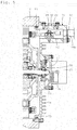
- Embodiment 2 shown in Fig. 7 differs in the configuration of the hub unit 15 compared with the above-described Embodiment 1. That is, the flange 22 of the outer member 21 of the hub unit 15 in this case is formed to have a larger diameter than that of the flange 22 (see Fig. 1 ) of the above-described Embodiment 1.
- a flange cylindrical portion 32 projecting in the axial direction is provided in the inner side surface of the flange 22 with a larger diameter.
- the flange cylindrical portion 32 extends over an outer radial surface of the flange 53 on the outboard side of the output member 14.
- the flange cylindrical portion 32 is fitted to an inner radial surface of the opening hole 19 of the front end portion 18 of the housing 16.
- the opening hole 19 is formed to have a large inner diameter, it is easy to fabricate the partition 24 which is integrated with the front end portion 18, in the case of this Embodiment 2. For this reason, in the case of Embodiment 2, the partition member 20 (see Fig. 1 ) which is a separate member is not used.
- a ball of a hub bearing 89a on the outboard side is placed between a track groove formed in the outer radial surface of the inner member 46, and a track groove formed in the inner radial surface of the outer member 21.
- the ball of the hub bearing 89b on the inboard side is placed between a track surface formed in the outer radial surface of the flange 52 and a track groove formed in an inner radial surface of the flange cylindrical portion 32.
- the hub unit 15 in this case can be said to be a variant form of the so-called third generation.
- each of the balls of the hub bearings 89a and 89b is configured to be in direct contact with the track groove, it is also possible to configure such that a bearing in which the track groove is provided in each of its inner ring and outer rings is used, and these track rings are fitted to the aforementioned opposite members.
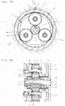
- Embodiment 3 shown in Figs. 8 to 10 differs from Embodiment 1 in the configurations of the hub unit 15, the rotation angle sensor 75, the power supply terminal box 76, and the connector insertion portion 78.
- the hub unit 15 in this case is formed such that the flange 22 of the outer member 21 has a larger diameter than in the case of Embodiment 1. For this reason, there is no need of adopting a partition portion 18a as in Embodiment 1, and the single housing 16 is used. The flange 22 with a larger diameter is secured to the housing 16 with the bolt 23.
- the ball 89a on the outboard side constituting the hub bearing is placed between the track groove provided in the outer radial surface of the inner member 46 and the track groove provided in the inner radial surface of the outer member 21. Further, the ball 89b on the inboard side is placed between the track groove provided in the outer radial surface of the output member 14 and the track groove provided in the inner radial surface of the outer member 21. It can be said to be a variant type of the so-called third-generation.
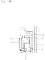
- the rotation angle sensor 75 is provided between opposite surfaces in the axial direction of the support member disc portion 31b of the rotor support member 31, and the partition disc portion 24a.
- a sensor rotor 91a is made up of a magnet which is attached to the support member disc portion 31b with a vis 92.
- a sensor stator 91b is made up of a Hall element attached to the opposite surface of the partition disc portion 24a with a vis 93. Both oppose each other via an axial gap.
- the cross sectional shape of the sensor rotor 91b may be formed into a reverse L-shape, and a radial gap may be formed between the horizontal portion of the sensor rotor 91b and the sensor stator 91a.
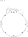
- the power supply terminal box 76 and the connector insertion portion 78 are both provided in the housing 16 (see Fig. 9 ).
- the power supply terminal box 76 is configured such that an accommodation recessed portion 94 is provided within the range of the wall thickness of a rear end surface of the housing 16, and the power supply terminal 82 is provided inside the accommodation recessed portion 94.
- a communication hole 95 in communication with the interior of the housing 16 is provided in a deep part of the accommodation recessed portion 94.
- the opening surface of the accommodation recessed portion 94 is blocked by a cover member 96.
- the cover member 96 is provided with a cable hole 97 for passing the power supply cable 84.
- the working hole 80 is provided in the wall surface of the housing 16. This working hole 80 is usually blocked by the cover 81.
- the lead wire 83 on the electric motor 11 side is connected to the power supply terminal 82 through the communication hole 95, and the power supply cable 84 is drawn in through the cable hole 97 so that its connection terminal is connected to the power supply terminal 82. Both are coupled to the power supply terminal 82 with a fastening screw 85.
- the connector insertion portion 78 is provided in the rear end surface of the housing 16 side-by-side with the power supply terminal box 76, as shown in Fig. 9 .
- the connector insertion portion 78 is configured such that a recessed portion 99 is provided in the rear end surface of the housing 16, and a lead wire hole 100 which brings a deep part of the recessed portion 99 and the interior of the housing 16 into communication is provided (see Fig. 8 ).
- a lead wire 101 of the rotation angle sensor 75 is connected to the interior of the recessed portion 99 through the lead wire hole 100.
- the connector (not shown) of the signal cable is inserted into the connector insertion portion 78.
- the configuration in which both the power supply terminal box 76 and the connector insertion portion 78 are provided in the housing 16 can simplify the configuration of the rear cover 73 so that it can be made up of a thin metal plate, a plastic plate, and the like.
Landscapes
- Engineering & Computer Science (AREA)
- Power Engineering (AREA)
- Chemical & Material Sciences (AREA)
- Combustion & Propulsion (AREA)
- Transportation (AREA)
- Mechanical Engineering (AREA)
- Microelectronics & Electronic Packaging (AREA)
- Arrangement Or Mounting Of Propulsion Units For Vehicles (AREA)
- Retarders (AREA)
- General Details Of Gearings (AREA)
Claims (6)
- Dispositif d'entraînement pour véhicule électrique, comprenant:un moteur électrique (11); une unité de réduction de vitesse (12) comprenant un arbre d'entrée (13) entraîné par la sortie du moteur électrique (11); une unité de moyeu (15) entraînée en rotation par un élément de sortie (14) de l'unité de réduction de vitesse (12); et un boîtier (16) logeant le moteur électrique (11) et l'unité de réduction de vitesse (12), dans laquelle l'arbre d'entrée (13) de l'unité de réduction de vitesse (12) est supporté par une paire de paliers (58, 59) prévus à deux endroits dans la direction axiale, le dispositif d'entraînement d'un véhicule électrique étant configuré de telle sorte que la paire de roulements (58, 59) sont tous deux supportés par l'élément de sortie (14), et le boîtier (16) est pourvu d'une partie cylindrique (17), d'une partie d'extrémité avant (18) dans la direction radiale, qui est prévue à l'extrémité avant de la partie cylindrique (17) et d'une partie de liaison de suspension (27)caractérisé en ce que chacun de la paire de paliers (58, 59) est composé d'un palier à roulement; une entretoise annulaire (64) est placée entre les bagues extérieures de la paire de roulements (58, 59); l'entretoise (64) est pourvue d'un trou de fenêtre (65) dans une partie qui s'oppose à l'élément rotatif de réduction de vitesse (43), où le trou de fenêtre (65) a pour but d'éviter les interférences; et une vis de fixation de l'entretoise (64) est vissée à partir d'une surface radiale externe du pont (54).
- Dispositif d'entraînement pour véhicule électrique selon la revendication 1, dans lequel
la partie de liaison de suspension (27) est prévue à deux emplacements centrosymétriques sur un bord d'extrémité arrière du boîtier (16). - Dispositif d'entraînement pour véhicule électrique selon la revendication 1 ou la revendication 2, comprenant une structure support dans laquelle la paire de paliers (58, 59) qui supportent l'arbre d'entrée (13) sont tous deux disposés sur un côté extérieur d'une partie de raccord entre l'arbre d'entrée (13) et l'élément support de rotor (31) du moteur électrique.
- Dispositif d'entraînement pour véhicule électrique selon la revendication 3, dans lequel
l'élément de sortie (14) comporte une paire de brides (52, 53) qui sont disposées des deux côtés dans une direction axiale d'un élément rotatif de réduction de vitesse (43) de l'unité de réduction de vitesse (12), les brides (52, 53) sont couplées et intégrées l'une à l'autre par les deux parties d' extrémité d'une broche de support (45) de l'élément rotatif de réduction de vitesse (43) solidaire de chaque bride (52, 53), et chacun des paliers (58, 59) est placé entre une surface radiale interne de chaque bride (52, 53) et l'arbre d'entrée (13). - Dispositif d'entraînement pour véhicule électrique selon la revendication 4, dans lequel
l'unité de réduction de vitesse (12) est du type à engrenage planétaire constitué d'une roue solaire (39) et d'une couronne dentée (42) qui sont prévues coaxialement à l'arbre d'entrée (13), plusieurs pignons (43) qui sont prévues à des positions équidistantes dans une direction circonférentielle entre la roue solaire (39) et la couronne dentée (42), et un support pour maintenir les pignons (43). - Dispositif d'entraînement pour véhicule électrique selon la revendication 5, dans lequel
l'unité de réduction de vitesse (12) est du type à engrenage planétaire, et les brides (52, 53) sont intégrées l'une à l'autre par des ponts (54) prévus à une distance requise dans une direction circonférentielle, les engrenages à pignons (43) sont logés entre les ponts respectifs (54), et les deux parties d'extrémité de la broche de pignon (45) sont supportées par les brides (52, 53), respectivement.
Applications Claiming Priority (2)
| Application Number | Priority Date | Filing Date | Title |
|---|---|---|---|
| JP2011049190A JP5604338B2 (ja) | 2011-03-07 | 2011-03-07 | 電気自動車用駆動装置 |
| PCT/JP2011/055398 WO2012120650A1 (fr) | 2011-03-07 | 2011-03-08 | Dispositif d'entraînement pour véhicule électrique |
Publications (3)
| Publication Number | Publication Date |
|---|---|
| EP2685609A1 EP2685609A1 (fr) | 2014-01-15 |
| EP2685609A4 EP2685609A4 (fr) | 2015-04-08 |
| EP2685609B1 true EP2685609B1 (fr) | 2018-05-09 |
Family
ID=46797653
Family Applications (1)
| Application Number | Title | Priority Date | Filing Date |
|---|---|---|---|
| EP11860425.5A Not-in-force EP2685609B1 (fr) | 2011-03-07 | 2011-03-08 | Dispositif d'entraînement pour véhicule électrique |
Country Status (5)
| Country | Link |
|---|---|
| US (1) | US9735648B2 (fr) |
| EP (1) | EP2685609B1 (fr) |
| JP (1) | JP5604338B2 (fr) |
| CN (1) | CN102792563B (fr) |
| WO (1) | WO2012120650A1 (fr) |
Families Citing this family (12)
| Publication number | Priority date | Publication date | Assignee | Title |
|---|---|---|---|---|
| JP6050220B2 (ja) * | 2013-12-10 | 2016-12-21 | 本田技研工業株式会社 | 内燃機関のジェネレータ冷却構造 |
| JP6445813B2 (ja) * | 2014-09-11 | 2018-12-26 | Ntn株式会社 | インホイールモータ駆動装置 |
| EP3965270A1 (fr) * | 2014-09-19 | 2022-03-09 | Siemens Aktiengesellschaft | Arbre en saillie pour un moteur électrique, moteur électrique doté d'un arbre en saillie, utilisation d'un arbre en saillie comme arbre d'entrainement d'un capteur de rotation, ainsi que procédé de liaison d'un arbre en saillie à un arbre de moteur d'un moteur électrique |
| CN104374369B (zh) * | 2014-11-12 | 2017-02-01 | 江苏金丰机电有限公司 | 一种电机转动检测装置 |
| EA030874B1 (ru) | 2015-05-08 | 2018-10-31 | Акционерное общество "Диаконт" | Линейный электромеханический привод |
| CN105291815B (zh) * | 2015-11-13 | 2017-08-15 | 湘电重型装备有限公司 | 一种电传动自卸车用电动轮 |
| JP6823417B2 (ja) * | 2016-09-30 | 2021-02-03 | Ntn株式会社 | インホイールモータ駆動装置 |
| JP6369614B1 (ja) * | 2017-09-29 | 2018-08-08 | トヨタ自動車株式会社 | 車両用ケーシング |
| JP7224198B2 (ja) * | 2019-02-08 | 2023-02-17 | Ntn株式会社 | 車両用動力装置および発電機付き車輪用軸受装置 |
| FR3112373B1 (fr) * | 2020-07-08 | 2023-04-21 | Innovaction Tech | Motoréducteur à enveloppe cylindrique et moteur tubulaire correspondant. |
| KR20230011139A (ko) * | 2021-07-13 | 2023-01-20 | 현대모비스 주식회사 | 허브 베어링을 포함하는 휠 구조체 및 그 휠 구조체를 포함하는 자동차 |
| CN116118477A (zh) * | 2022-09-02 | 2023-05-16 | 葵迪智能科技(上海)有限公司 | 轮毂动力总成及汽车 |
Family Cites Families (17)
| Publication number | Priority date | Publication date | Assignee | Title |
|---|---|---|---|---|
| US5087229A (en) * | 1991-05-06 | 1992-02-11 | General Motors Corporation | Independently suspended steerable motor wheel apparatus |
| JP4189089B2 (ja) * | 1999-07-23 | 2008-12-03 | アイシン・エィ・ダブリュ株式会社 | 電気自動車用ドライブユニット |
| JP3553436B2 (ja) * | 1999-10-19 | 2004-08-11 | ジヤトコ株式会社 | 電気式トルクコンバータ |
| US7420301B2 (en) * | 2004-10-04 | 2008-09-02 | Axletech International Ip Holdings, Llc | Wheel assembly with integral electric motor |
| JP2007022386A (ja) * | 2005-07-19 | 2007-02-01 | Ntn Corp | 電動式車輪駆動装置 |
| JP2007131295A (ja) * | 2005-10-11 | 2007-05-31 | Ntn Corp | 動力出力装置 |
| WO2007043514A1 (fr) * | 2005-10-11 | 2007-04-19 | Ntn Corporation | Dispositif de production de puissance |
| JP2007174725A (ja) * | 2005-12-19 | 2007-07-05 | Bridgestone Corp | インホイールモータシステム |
| WO2007069567A1 (fr) | 2005-12-12 | 2007-06-21 | Kabushiki Kaisha Bridgestone | Systeme de moteur de roue |
| JP4965131B2 (ja) * | 2006-01-27 | 2012-07-04 | トヨタ自動車株式会社 | インホイールモータ |
| JP4758852B2 (ja) * | 2006-08-29 | 2011-08-31 | 本田技研工業株式会社 | ホイール回転装置のブレーキ構造 |
| JP4724075B2 (ja) * | 2006-08-29 | 2011-07-13 | 本田技研工業株式会社 | ホイール回転装置 |
| ITTO20060894A1 (it) | 2006-12-15 | 2008-06-16 | Oto Melara Spa | Ruota motorizzata per un veicolo militare |
| JP5158861B2 (ja) * | 2008-03-11 | 2013-03-06 | Ntn株式会社 | インホイールモータ駆動装置 |
| CN102612614B (zh) * | 2009-11-16 | 2015-05-13 | 雷米技术有限公司 | 具有行星齿轮组的电动机 |
| CN101817306A (zh) * | 2010-05-06 | 2010-09-01 | 江苏大红成莱宝驰机车制造有限公司 | 一种电动汽车轮毂电机 |
| JP5565388B2 (ja) * | 2011-03-28 | 2014-08-06 | アイシン・エィ・ダブリュ株式会社 | インホイールモータ駆動装置 |
-
2011
- 2011-03-07 JP JP2011049190A patent/JP5604338B2/ja active Active
- 2011-03-08 US US14/003,668 patent/US9735648B2/en not_active Expired - Fee Related
- 2011-03-08 CN CN201180000156.4A patent/CN102792563B/zh not_active Expired - Fee Related
- 2011-03-08 WO PCT/JP2011/055398 patent/WO2012120650A1/fr not_active Ceased
- 2011-03-08 EP EP11860425.5A patent/EP2685609B1/fr not_active Not-in-force
Non-Patent Citations (1)
| Title |
|---|
| None * |
Also Published As
| Publication number | Publication date |
|---|---|
| US20130342058A1 (en) | 2013-12-26 |
| US9735648B2 (en) | 2017-08-15 |
| CN102792563A (zh) | 2012-11-21 |
| JP5604338B2 (ja) | 2014-10-08 |
| EP2685609A4 (fr) | 2015-04-08 |
| WO2012120650A1 (fr) | 2012-09-13 |
| JP2012183947A (ja) | 2012-09-27 |
| CN102792563B (zh) | 2019-11-01 |
| EP2685609A1 (fr) | 2014-01-15 |
Similar Documents
| Publication | Publication Date | Title |
|---|---|---|
| EP2684723B1 (fr) | Dispositif d'entraînement pour véhicule électrique | |
| EP2684722B1 (fr) | Dispositif d'entraînement pour véhicule électrique | |
| EP2685610B1 (fr) | Dispositif d'entraînement pour véhicule électrique | |
| EP2685609A1 (fr) | Dispositif d'entraînement pour véhicule électrique | |
| EP2685613B1 (fr) | Dispositif d'entraînement pour véhicule électrique | |
| US9657825B2 (en) | Drive device for vehicle | |
| JP2013071698A (ja) | 電気自動車用駆動装置 | |
| JP2013181645A (ja) | 電気自動車用駆動装置 | |
| JP5956552B2 (ja) | 電気自動車用駆動装置 | |
| JP2016111862A (ja) | 車両用モータ駆動装置の配線構造 | |
| JP2013040659A (ja) | 電気自動車用駆動装置 |
Legal Events
| Date | Code | Title | Description |
|---|---|---|---|
| PUAI | Public reference made under article 153(3) epc to a published international application that has entered the european phase |
Free format text: ORIGINAL CODE: 0009012 |
|
| 17P | Request for examination filed |
Effective date: 20131004 |
|
| AK | Designated contracting states |
Kind code of ref document: A1 Designated state(s): AL AT BE BG CH CY CZ DE DK EE ES FI FR GB GR HR HU IE IS IT LI LT LU LV MC MK MT NL NO PL PT RO RS SE SI SK SM TR |
|
| DAX | Request for extension of the european patent (deleted) | ||
| RIC1 | Information provided on ipc code assigned before grant |
Ipc: H02K 5/18 20060101ALI20141111BHEP Ipc: B60K 17/04 20060101ALI20141111BHEP Ipc: H02K 5/00 20060101AFI20141111BHEP Ipc: B60K 7/00 20060101ALI20141111BHEP Ipc: H02K 5/04 20060101ALI20141111BHEP |
|
| RA4 | Supplementary search report drawn up and despatched (corrected) |
Effective date: 20150309 |
|
| RIC1 | Information provided on ipc code assigned before grant |
Ipc: H02K 5/04 20060101ALI20150303BHEP Ipc: H02K 5/00 20060101AFI20150303BHEP Ipc: H02K 5/18 20060101ALI20150303BHEP Ipc: B60K 7/00 20060101ALI20150303BHEP Ipc: B60K 17/04 20060101ALI20150303BHEP |
|
| 17Q | First examination report despatched |
Effective date: 20160411 |
|
| STAA | Information on the status of an ep patent application or granted ep patent |
Free format text: STATUS: EXAMINATION IS IN PROGRESS |
|
| GRAP | Despatch of communication of intention to grant a patent |
Free format text: ORIGINAL CODE: EPIDOSNIGR1 |
|
| STAA | Information on the status of an ep patent application or granted ep patent |
Free format text: STATUS: GRANT OF PATENT IS INTENDED |
|
| INTG | Intention to grant announced |
Effective date: 20171129 |
|
| GRAS | Grant fee paid |
Free format text: ORIGINAL CODE: EPIDOSNIGR3 |
|
| GRAA | (expected) grant |
Free format text: ORIGINAL CODE: 0009210 |
|
| STAA | Information on the status of an ep patent application or granted ep patent |
Free format text: STATUS: THE PATENT HAS BEEN GRANTED |
|
| AK | Designated contracting states |
Kind code of ref document: B1 Designated state(s): AL AT BE BG CH CY CZ DE DK EE ES FI FR GB GR HR HU IE IS IT LI LT LU LV MC MK MT NL NO PL PT RO RS SE SI SK SM TR |
|
| REG | Reference to a national code |
Ref country code: GB Ref legal event code: FG4D |
|
| REG | Reference to a national code |
Ref country code: CH Ref legal event code: EP Ref country code: AT Ref legal event code: REF Ref document number: 998404 Country of ref document: AT Kind code of ref document: T Effective date: 20180515 |
|
| REG | Reference to a national code |
Ref country code: IE Ref legal event code: FG4D |
|
| REG | Reference to a national code |
Ref country code: DE Ref legal event code: R096 Ref document number: 602011048306 Country of ref document: DE |
|
| REG | Reference to a national code |
Ref country code: NL Ref legal event code: MP Effective date: 20180509 |
|
| REG | Reference to a national code |
Ref country code: LT Ref legal event code: MG4D |
|
| PG25 | Lapsed in a contracting state [announced via postgrant information from national office to epo] |
Ref country code: SE Free format text: LAPSE BECAUSE OF FAILURE TO SUBMIT A TRANSLATION OF THE DESCRIPTION OR TO PAY THE FEE WITHIN THE PRESCRIBED TIME-LIMIT Effective date: 20180509 Ref country code: LT Free format text: LAPSE BECAUSE OF FAILURE TO SUBMIT A TRANSLATION OF THE DESCRIPTION OR TO PAY THE FEE WITHIN THE PRESCRIBED TIME-LIMIT Effective date: 20180509 Ref country code: ES Free format text: LAPSE BECAUSE OF FAILURE TO SUBMIT A TRANSLATION OF THE DESCRIPTION OR TO PAY THE FEE WITHIN THE PRESCRIBED TIME-LIMIT Effective date: 20180509 Ref country code: NO Free format text: LAPSE BECAUSE OF FAILURE TO SUBMIT A TRANSLATION OF THE DESCRIPTION OR TO PAY THE FEE WITHIN THE PRESCRIBED TIME-LIMIT Effective date: 20180809 Ref country code: FI Free format text: LAPSE BECAUSE OF FAILURE TO SUBMIT A TRANSLATION OF THE DESCRIPTION OR TO PAY THE FEE WITHIN THE PRESCRIBED TIME-LIMIT Effective date: 20180509 Ref country code: BG Free format text: LAPSE BECAUSE OF FAILURE TO SUBMIT A TRANSLATION OF THE DESCRIPTION OR TO PAY THE FEE WITHIN THE PRESCRIBED TIME-LIMIT Effective date: 20180809 |
|
| PG25 | Lapsed in a contracting state [announced via postgrant information from national office to epo] |
Ref country code: GR Free format text: LAPSE BECAUSE OF FAILURE TO SUBMIT A TRANSLATION OF THE DESCRIPTION OR TO PAY THE FEE WITHIN THE PRESCRIBED TIME-LIMIT Effective date: 20180810 Ref country code: RS Free format text: LAPSE BECAUSE OF FAILURE TO SUBMIT A TRANSLATION OF THE DESCRIPTION OR TO PAY THE FEE WITHIN THE PRESCRIBED TIME-LIMIT Effective date: 20180509 Ref country code: HR Free format text: LAPSE BECAUSE OF FAILURE TO SUBMIT A TRANSLATION OF THE DESCRIPTION OR TO PAY THE FEE WITHIN THE PRESCRIBED TIME-LIMIT Effective date: 20180509 Ref country code: NL Free format text: LAPSE BECAUSE OF FAILURE TO SUBMIT A TRANSLATION OF THE DESCRIPTION OR TO PAY THE FEE WITHIN THE PRESCRIBED TIME-LIMIT Effective date: 20180509 Ref country code: LV Free format text: LAPSE BECAUSE OF FAILURE TO SUBMIT A TRANSLATION OF THE DESCRIPTION OR TO PAY THE FEE WITHIN THE PRESCRIBED TIME-LIMIT Effective date: 20180509 |
|
| REG | Reference to a national code |
Ref country code: AT Ref legal event code: MK05 Ref document number: 998404 Country of ref document: AT Kind code of ref document: T Effective date: 20180509 |
|
| PG25 | Lapsed in a contracting state [announced via postgrant information from national office to epo] |
Ref country code: DK Free format text: LAPSE BECAUSE OF FAILURE TO SUBMIT A TRANSLATION OF THE DESCRIPTION OR TO PAY THE FEE WITHIN THE PRESCRIBED TIME-LIMIT Effective date: 20180509 Ref country code: PL Free format text: LAPSE BECAUSE OF FAILURE TO SUBMIT A TRANSLATION OF THE DESCRIPTION OR TO PAY THE FEE WITHIN THE PRESCRIBED TIME-LIMIT Effective date: 20180509 Ref country code: SK Free format text: LAPSE BECAUSE OF FAILURE TO SUBMIT A TRANSLATION OF THE DESCRIPTION OR TO PAY THE FEE WITHIN THE PRESCRIBED TIME-LIMIT Effective date: 20180509 Ref country code: EE Free format text: LAPSE BECAUSE OF FAILURE TO SUBMIT A TRANSLATION OF THE DESCRIPTION OR TO PAY THE FEE WITHIN THE PRESCRIBED TIME-LIMIT Effective date: 20180509 Ref country code: CZ Free format text: LAPSE BECAUSE OF FAILURE TO SUBMIT A TRANSLATION OF THE DESCRIPTION OR TO PAY THE FEE WITHIN THE PRESCRIBED TIME-LIMIT Effective date: 20180509 Ref country code: AT Free format text: LAPSE BECAUSE OF FAILURE TO SUBMIT A TRANSLATION OF THE DESCRIPTION OR TO PAY THE FEE WITHIN THE PRESCRIBED TIME-LIMIT Effective date: 20180509 Ref country code: RO Free format text: LAPSE BECAUSE OF FAILURE TO SUBMIT A TRANSLATION OF THE DESCRIPTION OR TO PAY THE FEE WITHIN THE PRESCRIBED TIME-LIMIT Effective date: 20180509 |
|
| REG | Reference to a national code |
Ref country code: DE Ref legal event code: R097 Ref document number: 602011048306 Country of ref document: DE |
|
| PG25 | Lapsed in a contracting state [announced via postgrant information from national office to epo] |
Ref country code: SM Free format text: LAPSE BECAUSE OF FAILURE TO SUBMIT A TRANSLATION OF THE DESCRIPTION OR TO PAY THE FEE WITHIN THE PRESCRIBED TIME-LIMIT Effective date: 20180509 Ref country code: IT Free format text: LAPSE BECAUSE OF FAILURE TO SUBMIT A TRANSLATION OF THE DESCRIPTION OR TO PAY THE FEE WITHIN THE PRESCRIBED TIME-LIMIT Effective date: 20180509 |
|
| PLBE | No opposition filed within time limit |
Free format text: ORIGINAL CODE: 0009261 |
|
| STAA | Information on the status of an ep patent application or granted ep patent |
Free format text: STATUS: NO OPPOSITION FILED WITHIN TIME LIMIT |
|
| 26N | No opposition filed |
Effective date: 20190212 |
|
| PGFP | Annual fee paid to national office [announced via postgrant information from national office to epo] |
Ref country code: DE Payment date: 20190226 Year of fee payment: 9 |
|
| PG25 | Lapsed in a contracting state [announced via postgrant information from national office to epo] |
Ref country code: SI Free format text: LAPSE BECAUSE OF FAILURE TO SUBMIT A TRANSLATION OF THE DESCRIPTION OR TO PAY THE FEE WITHIN THE PRESCRIBED TIME-LIMIT Effective date: 20180509 |
|
| PGFP | Annual fee paid to national office [announced via postgrant information from national office to epo] |
Ref country code: FR Payment date: 20190213 Year of fee payment: 9 |
|
| PG25 | Lapsed in a contracting state [announced via postgrant information from national office to epo] |
Ref country code: MC Free format text: LAPSE BECAUSE OF FAILURE TO SUBMIT A TRANSLATION OF THE DESCRIPTION OR TO PAY THE FEE WITHIN THE PRESCRIBED TIME-LIMIT Effective date: 20180509 |
|
| REG | Reference to a national code |
Ref country code: CH Ref legal event code: PL |
|
| GBPC | Gb: european patent ceased through non-payment of renewal fee |
Effective date: 20190308 |
|
| PG25 | Lapsed in a contracting state [announced via postgrant information from national office to epo] |
Ref country code: AL Free format text: LAPSE BECAUSE OF FAILURE TO SUBMIT A TRANSLATION OF THE DESCRIPTION OR TO PAY THE FEE WITHIN THE PRESCRIBED TIME-LIMIT Effective date: 20180509 Ref country code: LU Free format text: LAPSE BECAUSE OF NON-PAYMENT OF DUE FEES Effective date: 20190308 |
|
| REG | Reference to a national code |
Ref country code: BE Ref legal event code: MM Effective date: 20190331 |
|
| PG25 | Lapsed in a contracting state [announced via postgrant information from national office to epo] |
Ref country code: LI Free format text: LAPSE BECAUSE OF NON-PAYMENT OF DUE FEES Effective date: 20190331 Ref country code: GB Free format text: LAPSE BECAUSE OF NON-PAYMENT OF DUE FEES Effective date: 20190308 Ref country code: IE Free format text: LAPSE BECAUSE OF NON-PAYMENT OF DUE FEES Effective date: 20190308 Ref country code: CH Free format text: LAPSE BECAUSE OF NON-PAYMENT OF DUE FEES Effective date: 20190331 |
|
| PG25 | Lapsed in a contracting state [announced via postgrant information from national office to epo] |
Ref country code: BE Free format text: LAPSE BECAUSE OF NON-PAYMENT OF DUE FEES Effective date: 20190331 |
|
| PG25 | Lapsed in a contracting state [announced via postgrant information from national office to epo] |
Ref country code: TR Free format text: LAPSE BECAUSE OF FAILURE TO SUBMIT A TRANSLATION OF THE DESCRIPTION OR TO PAY THE FEE WITHIN THE PRESCRIBED TIME-LIMIT Effective date: 20180509 |
|
| PG25 | Lapsed in a contracting state [announced via postgrant information from national office to epo] |
Ref country code: MT Free format text: LAPSE BECAUSE OF NON-PAYMENT OF DUE FEES Effective date: 20190308 Ref country code: PT Free format text: LAPSE BECAUSE OF FAILURE TO SUBMIT A TRANSLATION OF THE DESCRIPTION OR TO PAY THE FEE WITHIN THE PRESCRIBED TIME-LIMIT Effective date: 20180910 |
|
| REG | Reference to a national code |
Ref country code: DE Ref legal event code: R119 Ref document number: 602011048306 Country of ref document: DE |
|
| PG25 | Lapsed in a contracting state [announced via postgrant information from national office to epo] |
Ref country code: FR Free format text: LAPSE BECAUSE OF NON-PAYMENT OF DUE FEES Effective date: 20200331 Ref country code: DE Free format text: LAPSE BECAUSE OF NON-PAYMENT OF DUE FEES Effective date: 20201001 |
|
| PG25 | Lapsed in a contracting state [announced via postgrant information from national office to epo] |
Ref country code: CY Free format text: LAPSE BECAUSE OF FAILURE TO SUBMIT A TRANSLATION OF THE DESCRIPTION OR TO PAY THE FEE WITHIN THE PRESCRIBED TIME-LIMIT Effective date: 20180509 |
|
| PG25 | Lapsed in a contracting state [announced via postgrant information from national office to epo] |
Ref country code: IS Free format text: LAPSE BECAUSE OF FAILURE TO SUBMIT A TRANSLATION OF THE DESCRIPTION OR TO PAY THE FEE WITHIN THE PRESCRIBED TIME-LIMIT Effective date: 20180909 |
|
| PG25 | Lapsed in a contracting state [announced via postgrant information from national office to epo] |
Ref country code: HU Free format text: LAPSE BECAUSE OF FAILURE TO SUBMIT A TRANSLATION OF THE DESCRIPTION OR TO PAY THE FEE WITHIN THE PRESCRIBED TIME-LIMIT; INVALID AB INITIO Effective date: 20110308 |
|
| PG25 | Lapsed in a contracting state [announced via postgrant information from national office to epo] |
Ref country code: MK Free format text: LAPSE BECAUSE OF FAILURE TO SUBMIT A TRANSLATION OF THE DESCRIPTION OR TO PAY THE FEE WITHIN THE PRESCRIBED TIME-LIMIT Effective date: 20180509 |