EP2686630B1 - Vorrichtung zum durchströmenden behandeln von bahnförmigem material - Google Patents
Vorrichtung zum durchströmenden behandeln von bahnförmigem material Download PDFInfo
- Publication number
- EP2686630B1 EP2686630B1 EP12709842.4A EP12709842A EP2686630B1 EP 2686630 B1 EP2686630 B1 EP 2686630B1 EP 12709842 A EP12709842 A EP 12709842A EP 2686630 B1 EP2686630 B1 EP 2686630B1
- Authority
- EP
- European Patent Office
- Prior art keywords
- drum
- openings
- opening
- sheet
- length
- Prior art date
- Legal status (The legal status is an assumption and is not a legal conclusion. Google has not performed a legal analysis and makes no representation as to the accuracy of the status listed.)
- Not-in-force
Links
- 239000000463 material Substances 0.000 title claims description 20
- 230000007704 transition Effects 0.000 claims description 12
- 239000002184 metal Substances 0.000 claims description 9
- 238000001035 drying Methods 0.000 claims description 6
- 239000004753 textile Substances 0.000 claims description 5
- 239000004745 nonwoven fabric Substances 0.000 claims description 2
- 239000002759 woven fabric Substances 0.000 claims description 2
- 239000004744 fabric Substances 0.000 description 3
- 238000011161 development Methods 0.000 description 2
- 230000018109 developmental process Effects 0.000 description 2
- 206010013786 Dry skin Diseases 0.000 description 1
- 230000007423 decrease Effects 0.000 description 1
- 230000001419 dependent effect Effects 0.000 description 1
- 239000000835 fiber Substances 0.000 description 1
- 238000009998 heat setting Methods 0.000 description 1
- 238000000034 method Methods 0.000 description 1
- 230000002093 peripheral effect Effects 0.000 description 1
- 238000012216 screening Methods 0.000 description 1
- 230000003068 static effect Effects 0.000 description 1
Images

Classifications
-
- F—MECHANICAL ENGINEERING; LIGHTING; HEATING; WEAPONS; BLASTING
- F26—DRYING
- F26B—DRYING SOLID MATERIALS OR OBJECTS BY REMOVING LIQUID THEREFROM
- F26B13/00—Machines and apparatus for drying fabrics, fibres, yarns, or other materials in long lengths, with progressive movement
- F26B13/10—Arrangements for feeding, heating or supporting materials; Controlling movement, tension or position of materials
- F26B13/14—Rollers, drums, cylinders; Arrangement of drives, supports, bearings, cleaning
- F26B13/16—Rollers, drums, cylinders; Arrangement of drives, supports, bearings, cleaning perforated in combination with hot air blowing or suction devices, e.g. sieve drum dryers
-
- D—TEXTILES; PAPER
- D06—TREATMENT OF TEXTILES OR THE LIKE; LAUNDERING; FLEXIBLE MATERIALS NOT OTHERWISE PROVIDED FOR
- D06B—TREATING TEXTILE MATERIALS USING LIQUIDS, GASES OR VAPOURS
- D06B23/00—Component parts, details, or accessories of apparatus or machines, specially adapted for the treating of textile materials, not restricted to a particular kind of apparatus, provided for in groups D06B1/00 - D06B21/00
- D06B23/02—Rollers
- D06B23/025—Perforated rollers
-
- D—TEXTILES; PAPER
- D06—TREATMENT OF TEXTILES OR THE LIKE; LAUNDERING; FLEXIBLE MATERIALS NOT OTHERWISE PROVIDED FOR
- D06B—TREATING TEXTILE MATERIALS USING LIQUIDS, GASES OR VAPOURS
- D06B5/00—Forcing liquids, gases or vapours through textile materials to effect treatment, e.g. washing, dyeing, bleaching, sizing impregnating
- D06B5/02—Forcing liquids, gases or vapours through textile materials to effect treatment, e.g. washing, dyeing, bleaching, sizing impregnating through moving materials of indefinite length
- D06B5/08—Forcing liquids, gases or vapours through textile materials to effect treatment, e.g. washing, dyeing, bleaching, sizing impregnating through moving materials of indefinite length through fabrics
Definitions
- the invention relates to a device for through-flow treatment, in particular for drying sheet-like material according to the preamble of claim 1.
- a screen drum apparatus for passing through heat-treating gas-permeable material webs.
- a material carrying the web in its outer periphery permeable designed sieve drum is rotatably mounted.
- the sieve drum is placed under induced draft via a fan assigned to the front side as a suction air generator.
- the extracted air is heated in a part of the housing formed as an air treatment (ventilator space) and directed into the treatment space surrounding the sieve drum. Due to the negative pressure within the sieve drum, the heated air flows through the textile material web carried by the sieve drum.
- This known screening drum has an outer circumferential surface made of perforated sheet metal. This screen drum surface is additionally coated with a metallic screen cloth to even out the flow conditions.
- the DE 44 22 508 C1 describes a sieve drum of a drum dryer, consisting of a perforated drum shell and a screen fabric stretched over it. Between drum shell and screen fabric are metal strips for spacing.
- the openings have a cross section, wherein this may be a tapering in the radial direction of the drum cross section.
- the smallest cross section of the opening is the opening cross section, which is the maximum gas flow rate certainly.
- the maximum width of the opening cross section is the opening width of the opening.
- the openings each have an opening width d k and the transition to the drum surface a rounding radius r, wherein the ratio of rounding radius r to opening width d K of the openings is greater than 0.2, preferably between 0.3-0.4
- the openings have a flow-through length l K.
- the flowing length is the length of the respective opening in the drum plate in the radial direction.
- the flow-through length l K may be equal to the thickness D of the drum plate.
- the opening may be a round hole, wherein the diameter of the hole corresponds to the opening width.
- the opening may be a slot, a square hole or a polygonal hole.
- the openings may have a flow-through length which is greater than the thickness of the drum plate.
- the openings may be designed as passages introduced in the drum plate, in the manner of collar passages.
- the collar of each opening forms a directed towards the middle of the drum (radial direction) channel, which defines the length flowed through.
- the gas flowing through the opening in the drum sheet is thus directed through the adjoining duct. Overall, this results in a reduction of the flow resistance.
- Such a shaped drum surface causes a lower pressure loss when flowing through, preferably a lower static pressure loss.
- the gas flow rate limiting opening cross-section ie the gas flow rate limiting opening width or the gas flow rate limiting diameter of the openings, in the radial direction below the sheet metal underside lie the material web carrying drum plate.
- the opening cross-section can also lie within the bottom of the sheet metal.
- the openings may have a tapered cross-section in the radial direction.
- the openings may have a substantially conically tapering cross-section in the radial direction.
- the openings may have a tapered transition region with a consistent or nearly constant cross-section channel in the radial direction.
- the openings are for example. Made as produced by forming collar passages. The opening diameter decreases steadily starting from the upper side of the sheet metal. Depending on the type of forming tools used, a very rounded transition from the drum surface to the channel area formed by the collar or draft can be created. However, the openings may also be made by any other method. Thus, the opening can also be first perforated and embossed to produce the rounding radius. It is also possible to make a substantially conically tapered transition region between the drum surface and the lower end of the channel, the passage.
- the openings have a length / diameter ratio between 1 and 4, preferably between 1 and 2, wherein the ratio is formed from the length of the opening channel (plate surface - lower end channel) and the gas flow rate determining diameter of the opening.
- the invention is applicable to dryers in which the material web to be dried flows through hot air and thus expels the moisture in the material.
- the invention is likewise applicable to heat-setting devices in which, for example, a fleece consisting of fusible fibers and filaments is treated with hot air flowing through it and thus solidified.
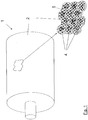
- FIG. 1 shows a drum 1, preferably a screen drum 1 with a gas-permeable, preferably air-permeable drum shell 2.
- the drum shell 2 is the outer peripheral surface of the drum first
- the drum 1 is rotatably mounted in a housing, not shown, and connected to a vacuum generator, not shown.
- the drum shell 2 is surrounded by a treatment room, not shown.
- a gaseous treatment medium preferably air
- the suction air generator not shown, generates a negative pressure in the interior of the drum.
- a web-shaped material to be treated can be placed on the gas-permeable drum shell 2.
- the gaseous treatment medium can at least partially flow through the material arranged on the drum shell 2 and the openings 4 of the drum shell 2 into the interior of the drum.
- the web-shaped material can be dried, for example.
- the gaseous treatment medium can be removed from the interior of the drum, processed and returned to the treatment room.
- the cylindrical drum shell 2 of the drum 1 consists of a sheet with a plurality of openings 4 distributed over the surface, which may be evenly distributed in a grid but also unevenly.
- the drum shell 2 has a drum surface 5.
- FIG. 1 shows an enlarged section of the drum shell 2 with the openings 4.
- the illustrated openings 4 are round holes. However, the openings may be of any shape.
- the openings 4 can be made as collar passages.
- openings 4 are round holes. These have a gas flow rate determining diameter corresponding to the opening width. However, it can alternatively be provided openings of any shape.
- openings have a channel 6 formed by the collar.
- the channel 6 of each opening 4 has the diameter.
- the entire length of the channel K and thus the opening 4- from the drum surface to the lower edge of the collar - is indicated by l K.
- FIG. 2 is the ratio of channel length l K to opening diameter greater than 1.
- the diameter of the opening 4 is greater than the channel length l K.
- the ratio of channel length l K to opening diameter is therefore smaller than 1.
- the openings 4 in the FIGS. 2 and 3 are rounded at the transition to the drum surface 5.
- the openings have a rounding radius r at the transition to the drum surface 5.
- the openings 4 are thus rounded off at the transition to the drum surface 5 with the rounding radius r.
- the ratio between rounding radius r and opening diameter d k is preferably greater than 0.2, more preferably between 0.3 and 0.4.
- FIG. 4 another embodiment of an opening is shown. This opening has no collar.
- the opening 4 has a length l K , which extends in the radial direction of the drum 1.
- the length l K of the opening 4 is equal to the thickness D of the sheet.
- the opening 4 is also a round hole which has a gas flow rate defining opening width. This opening width corresponds to the opening diameter.
- the opening 4 is also rounded off at the transition 6 to the drum surface 5 with a rounding radius r.
- the ratio of rounding radius r to opening width is preferably greater than 0.2, more preferably between 0.3 and 0.4. At this rounding radius, it has been found that the flow of the gaseous treatment medium flowing through the orifice is optimal.
Landscapes
- Engineering & Computer Science (AREA)
- Textile Engineering (AREA)
- Mechanical Engineering (AREA)
- General Engineering & Computer Science (AREA)
- Chemical & Material Sciences (AREA)
- Materials Engineering (AREA)
- Treatment Of Fiber Materials (AREA)
- Drying Of Solid Materials (AREA)
Description
- Die Erfindung betrifft eine Vorrichtung zum durchströmenden Behandeln, insbesondere zum Trocknen von bahnförmigem Material gemäß dem Oberbegriff von Anspruch 1.
- Aus der
DE 40 22 336 A1 ist eine Siebtrommelvorrichtung zum durchströmenden Wärmebehandeln von gasdurchlässigen Materialbahnen bekannt. In einem Gehäuse ist eine die Materialbahn tragende, in ihrem Außenumfang durchlässig gestaltete Siebtrommel drehbar gelagert. Über einen stirnseitig zugeordneten Ventilator als Sauglufterzeuger wird die Siebtrommel unter Saugzug gesetzt. Die abgesaugte Luft wird in einem als Luftaufbereitung (Ventilatorraum) ausgebildeten Teil des Gehäuses erwärmt und in den die Siebtrommel umgebenden Behandlungsraum geleitet. Durch den Unterdruck innerhalb der Siebtrommel durchströmt die erwärmte Luft die von der Siebtrommel getragene textile Materialbahn. - Diese bekannte Siebtrommel weist eine aus gelochtem Blech gefertigte Außenumfangsfläche auf. Diese Siebtrommelfläche ist zur Vergleichmäßigung der Strömungsverhältnisse zusätzlich mit einem metallischen Siebgewebe überzogen. Die
DE 44 22 508 C1 beschreibt eine Siebtrommel eines Trommeltrockners, bestehend aus einem gelochten Trommelmantel und einem darüber gespannten Siebgewebe. Zwischen Trommelmantel und Siebgewebe befinden sich Blechstreifen zur Beabstandung. -
GB 644594
DieDE 1 088 797 offenbart eine Saugwalze zum Entwässern von Stoff-, insbesondere Papierstoffbahnen, bei der die Saugöffnungen abgerundet sind.
Die Erfindung geht somit aus von einer Vorrichtung zum durchströmenden Behandeln einer gasdurchlässigen Bahn textilem Materials, insbesondere zum Trocknen von gewebten oder ungewebten Stoffen, bestehend aus: - eine drehbar gelagerte und mit einem Unterdruckerzeuger verbindbare Siebtrommel mit einer die Materialbahn tragenden, durchlässig gestalteten Außenumfangsfläche aus einem Blech mit einer Vielzahl darin angeordneter Öffnungen. Aufgabe der vorliegenden Erfindung ist es, eine Vorrichtung der gattungsgemäßen Art zu verbessern.
- Dies hat den Vorteil, dass das Strömungsverhalten des gasförmigen Behandlungsmediums, das durch die Öffnungen strömt, verbessert werden kann.
- Die Öffnungen weisen einen Querschnitt auf, wobei dieser ein in radialer Richtung der Trommel sich verjüngender Querschnitt sein kann. Der kleinste Querschnitt der Öffnung ist der Öffnungsquerschnitt, der den maximalen Gasdurchsatz bestimmt. Die maximale Breite des Öffnungsquerschnitts ist die Öffnungsweite der Öffnung.
- Die Öffnungen weisen jeweils eine Öffnungsweite dk und der Übergang zu der Trommeloberfläche einen Abrundungsradius r auf, wobei das Verhältnis von Abrundungsradius r zu Öffnungsweite dK der Öffnungen größer als 0,2, vorzugsweise zwischen 0,3-0,4, ist
- Die Öffnungen weisen eine durchströmende Länge lK auf. Die durchströmende Länge ist die Länge der jeweiligen Öffnung in dem Trommelblech in radialer Richtung. Die durchströmende Länge lK kann gleich der Dicke D des Trommelbleches sein.
- Die Öffnung kann ein rundes Loch sein, wobei der Durchmesser des Lochs der Öffnungsweite entspricht.
- Die Öffnung kann ein Langloch, ein Vierkantloch oder ein Vielkantloch sein.
- Die Öffnungen können eine durchströmte Länge aufweisen, welche größer ist als die Dicke des Trommelbleches.
- Die Öffnungen können als in dem Trommelblech eingebrachte Durchzüge, nach Art von Kragendurchzügen, ausgebildet sein. Der Kragen jeder Öffnung bildet einen in Richtung Trommelmitte (radiale Richtung) gerichteten Kanal dar, der die durchströmte Länge definiert. Das durch die Öffnung im Trommelblech strömende Gas wird so durch den sich anschließenden Kanal gerichtet. Insgesamt ergibt sich dadurch eine Reduktion des Strömungswiderstandes. Eine derartig gestaltete Trommeloberfläche bewirkt bei Durchströmung einen geringeren Druckverlust, vorzugsweise einen geringeren statischen Druckverlust.
- Die im Folgenden beschriebenen Weiterbildungen können einzeln oder in Kombination vorgesehen werden.
- Der den Gasdurchsatz begrenzende Öffnungsquerschnitt, d.h. die den Gasdurchsatz begrenzende Öffnungsweite bzw. der den Gasdurchsatz begrenzende Durchmesser der Öffnungen, kann in radialer Richtung unterhalb der Blechunterseite der die Materialbahn tragenden Trommelblechs liegen. Der Öffnungsquerschnitt kann auch innerhalb der Blechunterseite liegen.
- Die Öffnungen können in radialer Richtung einen sich verjüngen Querschnitt aufweisen.
- Die Öffnungen können in radialer Richtung einen sich im Wesentlichen konisch verjüngenden Querschnitt aufweisen.
- Die Öffnungen können einen sich verjüngenden Übergangsbereich mit einem sich in radialer Richtung daran anschließenden Kanal gleichbleibenden oder nahezu gleichbleibenden Querschnittes aufweisen.
- Bei den zuvor genannten Ausführungsformen sind die Öffnungen bspw. als mittels Umformung erzeugte Kragendurchzüge hergestellt. Der Öffnungsdurchmesser nimmt von der Blechoberseite beginnend stetig ab. Je nach Art der verwendeten Umformwerkzeuge kann ein sehr abgerundeter Übergang von der Trommeloberfläche zu dem durch den Kragen bzw. Durchzug gebildeten Kanalbereich erzeugt werden. Die Öffnungen können jedoch auch mit jedem beliebigen anderen Verfahren hergestellt werden. So kann die Öffnung auch zunächst gelocht werden und zur Herstellung des Abrundungsradius geprägt werden. Auch ist es möglich, einen im Wesentlich konisch sich Verjüngenden Übergangsbereich zwischen Trommeloberfläche und dem unteren Ende des Kanals, des Durchzuges zu gestalten.
- Die Öffnungen weisen ein Längen/Durchmesserverhältnis zwischen 1 und 4, vorzugsweise zwischen 1 und 2 auf, wobei das Verhältnis gebildet ist aus der Länge des Öffnungskanals (Blechoberfläche - unteres Ende Kanal) und dem den Gasdurchsatz bestimmenden Durchmesser der Öffnung.
- Die Erfindung ist anwendbar bei Trocknern, bei denen die zu trocknende Materialbahn mit heißer Luft durchströmt und so die Feuchtigkeit im Material ausgetrieben wird. Ebenfalls ist die Erfindung anwendbar bei der Thermofixierung dienenden Einrichtungen, bei denen beispielsweise ein aus schmelzbaren Fasern, Filamenten bestehendes Vlies mit heißer Luft durchströmend behandelt und so verfestigt wird.
- Des Weiteren erfolgt die Erläuterung eines Ausführungsbeispieles anhand der Zeichnung.
- Es zeigen schematisch:
- Fig.1
- eine Trommel mit gasdurchlässigem Trommelmantel,
- Fig.2
- ein Ausführungsbeispiel für eine Gestaltungsform der Öffnung,
- Fig.3
- ein weiteres Ausführungsbeispiel für eine Gestaltungsform der Öffnung,
- Fig.4
- ein weiteres Ausführungsbeispiel für eine Gestaltungsform der Öffnung.
-
Figur 1 zeigt eine Trommel 1, vorzugsweise eine Siebtrommel 1 mit einem gasdurchlässigen, vorzugsweise luftdurchlässigen Trommelmantel 2. Der Trommelmantel 2 ist die Außenumfangsfläche der Trommel 1. - Die Trommel 1 ist drehbar in einem nicht dargestellten Gehäuse gelagert und mit einem nicht dargestellten Sauglufterzeuger verbunden. Der Trommelmantel 2 ist von einem nicht dargestellten Behandlungsraum umgeben. In dem Behandlungsraum ist ein gasförmiges Behandlungsmedium, vorzugsweise Luft, angeordnet. Der nicht dargestellte Sauglufterzeuger erzeugt im Trommelinneren einen Unterdruck. Auf den gasdurchlässigen Trommelmantel 2 ist ein zu behandelndes bahnförmiges Gut plazierbar. Durch Anlegen des Unterdrucks im Trommelinnern kann das gasförmige Behandlungsmedium zumindest teilweise durch das auf dem Trommelmantel 2 angeordnete Gut und die Öffnungen 4 des Trommelmantels 2 in das Innere der Trommel strömen. Dadurch kann das bahnförmige Gut z.B. getrocknet werden. Das gasförmige Behandlungsmedium kann von dem Trommelinnern aus abgeführt, aufbereitet und dem Behandlungsraum wieder zugeführt werden.
- Der zylindrische Trommelmantel 2 der Trommel 1 besteht aus einem Blech mit einer Vielzahl über die Fläche verteilten Öffnungen 4, welche gleichmäßig in einem Raster aber auch ungleichmäßig verteilt sein können. Der Trommelmantel 2 weist eine Trommeloberfläche 5 auf.
-
Figur 1 zeigt einen vergrößerten Ausschnitt des Trommelmantels 2 mit den Öffnungen 4. Die dargestellten Öffnungen 4 sind runde Löcher. Die Öffnungen können jedoch jede beliebige Form aufweisen. Die Öffnungen 4 können als Kragendurchzüge hergestellt werden. - In den
Figur 2 und 3 sind Ausführungsbeispiele für Öffnungen im Schnitt dargestellt. Die dargestellten Öffnungen 4 sind runde Löcher. Diese weisen einen den Gasdurchsatz bestimmenden Durchmesser auf, der der Öffnungsweite entspricht. Es können alternativ jedoch auch Öffnungen beliebiger Form vorgesehen werden. - Diese Öffnungen weisen einen durch den Kragen gebildeten Kanal 6 auf. Der Kanal 6 einer jeden Öffnung 4 weist den Durchmesser auf. Die gesamte Länge des Kanals K und somit der Öffnung 4- von der Trommeloberfläche bis zur Unterkante des Kragens - ist mit lK angegeben.
- Die
Figuren 2 und 3 zeigen unterschiedliche Gestaltungsformen der erfindungsgemäßen Öffnungen 4. Bei der Öffnungsform nachFigur 2 ist das Verhältnis Kanallänge lK zu Öffnungsdurchmesser größer 1. Bei der Ausführung nachFigur 3 - kurzer Kragen - ist der Durchmesser der Öffnung 4 größer als die Kanallänge lK. Das Verhältnis Kanallänge lK zu Öffnungsdurchmesser ist daher kleiner 1. - Die Öffnungen 4 in den
Figuren 2 und 3 sind an dem Übergang zu der Trommeloberfläche 5 abgerundet. Die Öffnungen weisen an dem Übergang zu der Trommeloberfläche 5 einen Abrundungsradius r auf. Die Öffnungen 4 sind an dem Übergang zu der Trommeloberfläche 5 somit mit dem Abrundungsradius r abgerundet. - Das Verhältnis zwischen Abrundungsradius r und Öffnungsdurchmesser dk ist vorzugsweise größer als 0,2, besonders bevorzugt zwischen 0,3 und 0,4.
- In
Figur 4 ist ein weiteres Ausführungsbeispiel für eine Öffnung dargestellt. Diese Öffnung weist keinen Kragen auf. Die Öffnung 4 weist eine Länge lK auf, die sich in radialer Richtung der Trommel 1 erstreckt. Die Länge lK der Öffnung 4 ist gleich der Dicke D des Blechs. - Die Öffnung 4 ist ebenfalls ein rundes Loch, das eine den Gasdurchsatz bestimmende Öffnungsweite aufweist. Diese Öffnungsweite entspricht dem Öffnungsdurchmesser.
- Die Öffnung 4 ist ebenfalls an dem Übergang 6 zu der Trommeloberfläche 5 mit einem Abrundungsradius r abgerundet. Auch bei diesem Ausführungsbeispiel ist das Verhältnis von Abrundungsradius r zu Öffnungsweite vorzugsweise größer als 0,2, besonders bevorzugt zwischen 0,3 und 0,4. Bei diesem Abrundungsradius ist festgestellt worden, dass die Strömung des gasförmigen Behandlungsmediums, das durch die Öffnung strömt, optimal ist.
Gemäß der Erfindung ist eine Vorrichtung zum Behandeln eines bahnförmigen Guts, insbesondere zum Trocknen einer vorzugsweise textilen Warenbahn, mit einem gasförmigen Behandlungsmedium, vorgesehen. Die Vorrichtung weist eine Trommel, die einen gasdurchlässigen Trommelmantel aufweist, auf. Der Trommelmantel ist aus einem Trommelblech gebildet ist, das eine Vielzahl von Öffnungen aufweist, wobei der Trommelmantel eine Trommeloberfläche aufweist, auf die das zu behandelnde Gut plazierbar ist. In vorteilhafterweise ist vorgesehen, dass die Öffnungen an dem Übergang zu der Trommeloberfläche abgerundet sind.
Claims (9)
- Vorrichtung zum durchströmenden Behandeln einer gasdurchlässigen Bahn textilen Materials, insbesondere zum Trocknen von gewebten oder ungewebten Stoffen, mit
einer drehbar gelagerten und mit einem Unterdruckerzeuger verbindbaren Siebtrommel (1) mit einer die Materialbahn tragenden, durchlässig gestalteten Außenumfangsfläche aus einem Blech mit einer Vielzahl darin angeordneter Öffnungen, wobei die Öffnungen (4) eine durchströmte Länge (lK) aufweisen, welche größer ist als die Dicke (D) des Trommelbleches (2), dadurch gekennzeichnet, dass die Öffnungen (4) als in dem Trommelblech (2) eingebrachte Durchzüge, nach Art von Kragendurchzügen (6), ausgebildet sind. - Vorrichtung nach Anspruch 1, dadurch gekennzeichnet, dass der den Gasdurchsatz begrenzende Durchmesser (dK) der Öffnungen (4) in radialer Richtung der Trommel (1) unterhalb der Blechunterseite der die Materialbahn tragenden Trommelblechs (2) liegt.
- Vorrichtung nach Anspruch 1 oder 2, dadurch gekennzeichnet, dass die Öffnungen (4) in radialer Richtung einen sich verjüngen Querschnitt aufweisen.
- Vorrichtung nach Anspruch 3, dadurch gekennzeichnet, dass die Öffnungen (4) in radialer Richtung einen sich im Wesentlichen konisch verjüngenden Querschnitt aufweisen.
- Vorrichtung nach einem der Ansprüche 1 bis 4, dadurch gekennzeichnet, dass die Öffnungen (4) einen sich verjüngenden Übergangsbereich mit einem sich in radialer Richtung daran anschließenden Kanal (6) gleichbleibenden oder nahezu gleichbleibenden Querschnittes aufweisen.
- Vorrichtung nach einem der vorhergehenden Ansprüche, dadurch gekennzeichnet, dass die Öffnungen (4) ein Längen/Durchmesserverhältnis (lK/dK) zwischen 1 und 4 weisen, vorzugsweise zwischen 1 und 2 auf, wobei das Verhältnis gebildet ist aus der Länge (lK) des Öffnungskanals (Blechoberfläche - unteres Ende Kanal) und dem den Gasdurchsatz bestimmenden Durchmesser (dK) der Öffnung (4).
- Vorrichtung zum Behandeln eines bahnförmigen Guts, insbesondere zum Trocknen einer vorzugsweise textilen Warenbahn, mit einem gasförmigen Behandlungsmedium, mit
einer Trommel (1), die einen gasdurchlässigen Trommelmantel (2) aufweist, der aus einem Trommelblech gebildet ist, das eine Vielzahl von Öffnungen aufweist, wobei der Trommelmantel (2) eine Trommeloberfläche (5) aufweist auf die das zu behandelnde Gut plazierbar ist, wobei die Öffnungen (4) an dem Übergang zu der Trommeloberfläche (5) abgerundet sind.
dadurch gekennzeichnet, dass
die Öffnungen (4) jeweils eine Öffnungsweite B aufweisen und der Übergang zu der Trommeloberfläche (5) einen Abrundungsradius r aufweisen, wobei das Verhältnis von Abrundungsradius (r) zu Öffnungsweite B der Öffnungen (4) zwischen 0,3-0,4 ist. - Vorrichtung nach Anspruch 7, dadurch gekennzeichnet, dass die Öffnungen (4) eine durchströmte Länge (lK) aufweisen, wobei die durchströmende Länge (lK) gleich der Dicke (D) des Trommelbleches (2) ist.
- Vorrichtung nach einem der Ansprüche 7 bis 8, dadurch gekennzeichnet, dass die Öffnung (4) ein rundes Loch ist, wobei der Durchmesser des Lochs der Öffnungsweite B entspricht.
Applications Claiming Priority (3)
| Application Number | Priority Date | Filing Date | Title |
|---|---|---|---|
| DE102011013927 | 2011-03-14 | ||
| DE102011113834A DE102011113834A1 (de) | 2011-03-14 | 2011-09-21 | Vorrichtung zum durchströmenden Behandeln von bahnförmigem Material |
| PCT/EP2012/054465 WO2012123497A1 (de) | 2011-03-14 | 2012-03-14 | Vorrichtung zum durchströmenden behandeln von bahnförmigem material |
Publications (2)
| Publication Number | Publication Date |
|---|---|
| EP2686630A1 EP2686630A1 (de) | 2014-01-22 |
| EP2686630B1 true EP2686630B1 (de) | 2018-11-07 |
Family
ID=46756939
Family Applications (1)
| Application Number | Title | Priority Date | Filing Date |
|---|---|---|---|
| EP12709842.4A Not-in-force EP2686630B1 (de) | 2011-03-14 | 2012-03-14 | Vorrichtung zum durchströmenden behandeln von bahnförmigem material |
Country Status (4)
| Country | Link |
|---|---|
| EP (1) | EP2686630B1 (de) |
| CN (1) | CN103429980B (de) |
| DE (1) | DE102011113834A1 (de) |
| WO (1) | WO2012123497A1 (de) |
Families Citing this family (1)
| Publication number | Priority date | Publication date | Assignee | Title |
|---|---|---|---|---|
| DE102014105060A1 (de) * | 2014-04-09 | 2015-10-15 | Trützschler GmbH + Co KG Textilmaschinenfabrik | Trockner für eine textile Warenbahn |
Family Cites Families (9)
| Publication number | Priority date | Publication date | Assignee | Title |
|---|---|---|---|---|
| FR963222A (de) * | 1950-07-01 | |||
| GB644594A (en) * | 1947-07-17 | 1950-10-11 | Walmsleys Bury Ltd | Improvements in or relating to perforated rolls for paper-making machines and the like |
| DE1088797B (de) * | 1957-06-08 | 1960-09-08 | Doerries A G O | Saugwalze zum Entwaessern von Stoff-, insbesondere Papierstoffbahnen |
| US4076582A (en) * | 1977-04-04 | 1978-02-28 | Diamond International Corporation | Suction roll sealing strip cleaning structure |
| DE4010430A1 (de) * | 1990-03-31 | 1991-10-02 | Guenter Schirm | Trommelfaerbemaschine |
| DE4022336A1 (de) | 1990-07-13 | 1992-01-16 | Fleissner Maschf Ag | Vorrichtung zum durchstroemenden behandeln von bahnfoermigem gut |
| DE4422508C1 (de) | 1994-06-28 | 1996-02-15 | Fleissner Maschf Gmbh Co | Vorrichtung zum durchströmenden Behandeln von Textilgut od. dgl. |
| JP2006077337A (ja) * | 2004-09-08 | 2006-03-23 | Nissen Corp | 布帛の液流式処理装置における布帛牽引装置 |
| DE102006007834A1 (de) * | 2006-02-17 | 2007-09-06 | Fleissner Gmbh | Trommelschale zur Erzeugung von Strukturen und/oder Reliefmuster auf der Oberfläche eines gewebten oder nicht gewebten Zellenmaterials oder Vlieses |
-
2011
- 2011-09-21 DE DE102011113834A patent/DE102011113834A1/de not_active Withdrawn
-
2012
- 2012-03-14 CN CN201280013040.9A patent/CN103429980B/zh not_active Expired - Fee Related
- 2012-03-14 WO PCT/EP2012/054465 patent/WO2012123497A1/de not_active Ceased
- 2012-03-14 EP EP12709842.4A patent/EP2686630B1/de not_active Not-in-force
Non-Patent Citations (1)
| Title |
|---|
| None * |
Also Published As
| Publication number | Publication date |
|---|---|
| DE102011113834A1 (de) | 2012-09-20 |
| EP2686630A1 (de) | 2014-01-22 |
| WO2012123497A1 (de) | 2012-09-20 |
| CN103429980A (zh) | 2013-12-04 |
| CN103429980B (zh) | 2015-08-26 |
Similar Documents
| Publication | Publication Date | Title |
|---|---|---|
| EP2689060B1 (de) | EINRICHTUNG ZUR VERFESTIGUNG EINES TEXTILEN PRODUKTES MITTELS HEIßEN GASEN | |
| EP0465769B1 (de) | Vorrichtung zum durchströmenden Behandeln von bahnförmigem Gut | |
| EP1120490A2 (de) | Former und Verfahren zur Herstellung einer Tissuebahn | |
| EP3165861B1 (de) | Vorrichtung zum durchströmenden behandeln von bahnförmigem material | |
| EP2041344B1 (de) | Vorrichtung zur herstellung von textilien, vliesstoffen, spinnvliesen, papierwerkstoffen und/oder perforierten folien | |
| EP3212843B1 (de) | Vorrichtung zur entwässerung einer faserstoffbahn | |
| DE102015118596A1 (de) | Vorrichtung und Verfahren zum thermischen Behandeln einer textilen Warenbahn | |
| WO2012055732A1 (de) | Vorrichtung zum durchströmenden behandeln von bahnförmigem material | |
| DE102011005101A1 (de) | Textilbehandlungsmaschine und Verfahren zum Trocknen textiler Strukturen | |
| EP2930451B1 (de) | Trockner für eine textile warenbahn | |
| EP2686630B1 (de) | Vorrichtung zum durchströmenden behandeln von bahnförmigem material | |
| EP1048914B1 (de) | Siebtrommelvorrichtung zum Trocknen von durchlässigen Warenbahnen | |
| DE1604783A1 (de) | Vorrichtung zum Waermebehandeln von vorzugsweise auf Laengszug beanspruchbarem Gut mit Siebtrommeln | |
| EP3556922B1 (de) | Vorrichtung zum thermischen behandeln einer textilen warenbahn | |
| DE102019124401A1 (de) | Vorrichtung zum thermischen Behandeln einer textilen Warenbahn | |
| DE102011086428A1 (de) | Sieb | |
| DE1002722B (de) | Siebtrommeltrockner fuer Fasermaterial | |
| DE19922429A1 (de) | Vorrichtung und Verfahren zur kontinuierlichen Behandlung von luftdurchlässigen, textilen Materialwarenbahnen | |
| AT510088A2 (de) | Ein verfahren zur beherrschung des einrollens der faserstoffbahn und eine trockenpartie einer faserbahnmaschine | |
| DE202008017262U1 (de) | Vorrichtung zur Herstellung eines verfestigten Verbundwerkstoffes aus Fasern und Fäden | |
| DE102012103413A1 (de) | Maschine zur aerodynamischen Vliesbildung | |
| DE2116486B2 (de) | Verfahren und vorrichtung zum kraeuseln von synthesefasern | |
| CH421823A (de) | Siebwalzentrockner für luftundurchlässiges oder schwer durchlässiges Gut | |
| DE102011089551A1 (de) | Verfahren zur Konditionierung eines endlos umlaufenden Trockenbandesund Kontakttrockenvorrichtung | |
| CH421034A (de) | Trommeltrockner für luftdurchlässige Materialien |
Legal Events
| Date | Code | Title | Description |
|---|---|---|---|
| PUAI | Public reference made under article 153(3) epc to a published international application that has entered the european phase |
Free format text: ORIGINAL CODE: 0009012 |
|
| 17P | Request for examination filed |
Effective date: 20130913 |
|
| AK | Designated contracting states |
Kind code of ref document: A1 Designated state(s): AL AT BE BG CH CY CZ DE DK EE ES FI FR GB GR HR HU IE IS IT LI LT LU LV MC MK MT NL NO PL PT RO RS SE SI SK SM TR |
|
| DAX | Request for extension of the european patent (deleted) | ||
| STAA | Information on the status of an ep patent application or granted ep patent |
Free format text: STATUS: EXAMINATION IS IN PROGRESS |
|
| 17Q | First examination report despatched |
Effective date: 20170127 |
|
| GRAP | Despatch of communication of intention to grant a patent |
Free format text: ORIGINAL CODE: EPIDOSNIGR1 |
|
| STAA | Information on the status of an ep patent application or granted ep patent |
Free format text: STATUS: GRANT OF PATENT IS INTENDED |
|
| INTG | Intention to grant announced |
Effective date: 20180601 |
|
| RAP1 | Party data changed (applicant data changed or rights of an application transferred) |
Owner name: TRUETZSCHLER NONWOVENS & MAN-MADE FIBERS GMBH |
|
| GRAS | Grant fee paid |
Free format text: ORIGINAL CODE: EPIDOSNIGR3 |
|
| GRAA | (expected) grant |
Free format text: ORIGINAL CODE: 0009210 |
|
| STAA | Information on the status of an ep patent application or granted ep patent |
Free format text: STATUS: THE PATENT HAS BEEN GRANTED |
|
| AK | Designated contracting states |
Kind code of ref document: B1 Designated state(s): AL AT BE BG CH CY CZ DE DK EE ES FI FR GB GR HR HU IE IS IT LI LT LU LV MC MK MT NL NO PL PT RO RS SE SI SK SM TR |
|
| REG | Reference to a national code |
Ref country code: GB Ref legal event code: FG4D Free format text: NOT ENGLISH |
|
| REG | Reference to a national code |
Ref country code: CH Ref legal event code: EP Ref country code: AT Ref legal event code: REF Ref document number: 1062545 Country of ref document: AT Kind code of ref document: T Effective date: 20181115 |
|
| REG | Reference to a national code |
Ref country code: IE Ref legal event code: FG4D Free format text: LANGUAGE OF EP DOCUMENT: GERMAN |
|
| REG | Reference to a national code |
Ref country code: DE Ref legal event code: R096 Ref document number: 502012013767 Country of ref document: DE |
|
| REG | Reference to a national code |
Ref country code: NL Ref legal event code: MP Effective date: 20181107 |
|
| REG | Reference to a national code |
Ref country code: LT Ref legal event code: MG4D |
|
| PG25 | Lapsed in a contracting state [announced via postgrant information from national office to epo] |
Ref country code: LV Free format text: LAPSE BECAUSE OF FAILURE TO SUBMIT A TRANSLATION OF THE DESCRIPTION OR TO PAY THE FEE WITHIN THE PRESCRIBED TIME-LIMIT Effective date: 20181107 Ref country code: ES Free format text: LAPSE BECAUSE OF FAILURE TO SUBMIT A TRANSLATION OF THE DESCRIPTION OR TO PAY THE FEE WITHIN THE PRESCRIBED TIME-LIMIT Effective date: 20181107 Ref country code: LT Free format text: LAPSE BECAUSE OF FAILURE TO SUBMIT A TRANSLATION OF THE DESCRIPTION OR TO PAY THE FEE WITHIN THE PRESCRIBED TIME-LIMIT Effective date: 20181107 Ref country code: IS Free format text: LAPSE BECAUSE OF FAILURE TO SUBMIT A TRANSLATION OF THE DESCRIPTION OR TO PAY THE FEE WITHIN THE PRESCRIBED TIME-LIMIT Effective date: 20190307 Ref country code: NO Free format text: LAPSE BECAUSE OF FAILURE TO SUBMIT A TRANSLATION OF THE DESCRIPTION OR TO PAY THE FEE WITHIN THE PRESCRIBED TIME-LIMIT Effective date: 20190207 Ref country code: FI Free format text: LAPSE BECAUSE OF FAILURE TO SUBMIT A TRANSLATION OF THE DESCRIPTION OR TO PAY THE FEE WITHIN THE PRESCRIBED TIME-LIMIT Effective date: 20181107 Ref country code: BG Free format text: LAPSE BECAUSE OF FAILURE TO SUBMIT A TRANSLATION OF THE DESCRIPTION OR TO PAY THE FEE WITHIN THE PRESCRIBED TIME-LIMIT Effective date: 20190207 Ref country code: HR Free format text: LAPSE BECAUSE OF FAILURE TO SUBMIT A TRANSLATION OF THE DESCRIPTION OR TO PAY THE FEE WITHIN THE PRESCRIBED TIME-LIMIT Effective date: 20181107 |
|
| PG25 | Lapsed in a contracting state [announced via postgrant information from national office to epo] |
Ref country code: GR Free format text: LAPSE BECAUSE OF FAILURE TO SUBMIT A TRANSLATION OF THE DESCRIPTION OR TO PAY THE FEE WITHIN THE PRESCRIBED TIME-LIMIT Effective date: 20190208 Ref country code: RS Free format text: LAPSE BECAUSE OF FAILURE TO SUBMIT A TRANSLATION OF THE DESCRIPTION OR TO PAY THE FEE WITHIN THE PRESCRIBED TIME-LIMIT Effective date: 20181107 Ref country code: AL Free format text: LAPSE BECAUSE OF FAILURE TO SUBMIT A TRANSLATION OF THE DESCRIPTION OR TO PAY THE FEE WITHIN THE PRESCRIBED TIME-LIMIT Effective date: 20181107 Ref country code: SE Free format text: LAPSE BECAUSE OF FAILURE TO SUBMIT A TRANSLATION OF THE DESCRIPTION OR TO PAY THE FEE WITHIN THE PRESCRIBED TIME-LIMIT Effective date: 20181107 Ref country code: PT Free format text: LAPSE BECAUSE OF FAILURE TO SUBMIT A TRANSLATION OF THE DESCRIPTION OR TO PAY THE FEE WITHIN THE PRESCRIBED TIME-LIMIT Effective date: 20190307 Ref country code: NL Free format text: LAPSE BECAUSE OF FAILURE TO SUBMIT A TRANSLATION OF THE DESCRIPTION OR TO PAY THE FEE WITHIN THE PRESCRIBED TIME-LIMIT Effective date: 20181107 |
|
| PG25 | Lapsed in a contracting state [announced via postgrant information from national office to epo] |
Ref country code: PL Free format text: LAPSE BECAUSE OF FAILURE TO SUBMIT A TRANSLATION OF THE DESCRIPTION OR TO PAY THE FEE WITHIN THE PRESCRIBED TIME-LIMIT Effective date: 20181107 Ref country code: DK Free format text: LAPSE BECAUSE OF FAILURE TO SUBMIT A TRANSLATION OF THE DESCRIPTION OR TO PAY THE FEE WITHIN THE PRESCRIBED TIME-LIMIT Effective date: 20181107 Ref country code: CZ Free format text: LAPSE BECAUSE OF FAILURE TO SUBMIT A TRANSLATION OF THE DESCRIPTION OR TO PAY THE FEE WITHIN THE PRESCRIBED TIME-LIMIT Effective date: 20181107 |
|
| REG | Reference to a national code |
Ref country code: DE Ref legal event code: R097 Ref document number: 502012013767 Country of ref document: DE |
|
| PG25 | Lapsed in a contracting state [announced via postgrant information from national office to epo] |
Ref country code: RO Free format text: LAPSE BECAUSE OF FAILURE TO SUBMIT A TRANSLATION OF THE DESCRIPTION OR TO PAY THE FEE WITHIN THE PRESCRIBED TIME-LIMIT Effective date: 20181107 Ref country code: EE Free format text: LAPSE BECAUSE OF FAILURE TO SUBMIT A TRANSLATION OF THE DESCRIPTION OR TO PAY THE FEE WITHIN THE PRESCRIBED TIME-LIMIT Effective date: 20181107 Ref country code: SM Free format text: LAPSE BECAUSE OF FAILURE TO SUBMIT A TRANSLATION OF THE DESCRIPTION OR TO PAY THE FEE WITHIN THE PRESCRIBED TIME-LIMIT Effective date: 20181107 Ref country code: SK Free format text: LAPSE BECAUSE OF FAILURE TO SUBMIT A TRANSLATION OF THE DESCRIPTION OR TO PAY THE FEE WITHIN THE PRESCRIBED TIME-LIMIT Effective date: 20181107 |
|
| PLBE | No opposition filed within time limit |
Free format text: ORIGINAL CODE: 0009261 |
|
| STAA | Information on the status of an ep patent application or granted ep patent |
Free format text: STATUS: NO OPPOSITION FILED WITHIN TIME LIMIT |
|
| 26N | No opposition filed |
Effective date: 20190808 |
|
| PG25 | Lapsed in a contracting state [announced via postgrant information from national office to epo] |
Ref country code: SI Free format text: LAPSE BECAUSE OF FAILURE TO SUBMIT A TRANSLATION OF THE DESCRIPTION OR TO PAY THE FEE WITHIN THE PRESCRIBED TIME-LIMIT Effective date: 20181107 Ref country code: MC Free format text: LAPSE BECAUSE OF FAILURE TO SUBMIT A TRANSLATION OF THE DESCRIPTION OR TO PAY THE FEE WITHIN THE PRESCRIBED TIME-LIMIT Effective date: 20181107 |
|
| REG | Reference to a national code |
Ref country code: CH Ref legal event code: PL |
|
| GBPC | Gb: european patent ceased through non-payment of renewal fee |
Effective date: 20190314 |
|
| PG25 | Lapsed in a contracting state [announced via postgrant information from national office to epo] |
Ref country code: LU Free format text: LAPSE BECAUSE OF NON-PAYMENT OF DUE FEES Effective date: 20190314 |
|
| REG | Reference to a national code |
Ref country code: BE Ref legal event code: MM Effective date: 20190331 |
|
| PG25 | Lapsed in a contracting state [announced via postgrant information from national office to epo] |
Ref country code: GB Free format text: LAPSE BECAUSE OF NON-PAYMENT OF DUE FEES Effective date: 20190314 Ref country code: CH Free format text: LAPSE BECAUSE OF NON-PAYMENT OF DUE FEES Effective date: 20190331 Ref country code: LI Free format text: LAPSE BECAUSE OF NON-PAYMENT OF DUE FEES Effective date: 20190331 Ref country code: IE Free format text: LAPSE BECAUSE OF NON-PAYMENT OF DUE FEES Effective date: 20190314 |
|
| PG25 | Lapsed in a contracting state [announced via postgrant information from national office to epo] |
Ref country code: BE Free format text: LAPSE BECAUSE OF NON-PAYMENT OF DUE FEES Effective date: 20190331 |
|
| PG25 | Lapsed in a contracting state [announced via postgrant information from national office to epo] |
Ref country code: TR Free format text: LAPSE BECAUSE OF FAILURE TO SUBMIT A TRANSLATION OF THE DESCRIPTION OR TO PAY THE FEE WITHIN THE PRESCRIBED TIME-LIMIT Effective date: 20181107 |
|
| PGFP | Annual fee paid to national office [announced via postgrant information from national office to epo] |
Ref country code: DE Payment date: 20200320 Year of fee payment: 9 Ref country code: AT Payment date: 20200320 Year of fee payment: 9 |
|
| PG25 | Lapsed in a contracting state [announced via postgrant information from national office to epo] |
Ref country code: MT Free format text: LAPSE BECAUSE OF FAILURE TO SUBMIT A TRANSLATION OF THE DESCRIPTION OR TO PAY THE FEE WITHIN THE PRESCRIBED TIME-LIMIT Effective date: 20181107 |
|
| PGFP | Annual fee paid to national office [announced via postgrant information from national office to epo] |
Ref country code: FR Payment date: 20200320 Year of fee payment: 9 |
|
| PGFP | Annual fee paid to national office [announced via postgrant information from national office to epo] |
Ref country code: IT Payment date: 20200318 Year of fee payment: 9 |
|
| PG25 | Lapsed in a contracting state [announced via postgrant information from national office to epo] |
Ref country code: CY Free format text: LAPSE BECAUSE OF FAILURE TO SUBMIT A TRANSLATION OF THE DESCRIPTION OR TO PAY THE FEE WITHIN THE PRESCRIBED TIME-LIMIT Effective date: 20181107 |
|
| PG25 | Lapsed in a contracting state [announced via postgrant information from national office to epo] |
Ref country code: HU Free format text: LAPSE BECAUSE OF FAILURE TO SUBMIT A TRANSLATION OF THE DESCRIPTION OR TO PAY THE FEE WITHIN THE PRESCRIBED TIME-LIMIT; INVALID AB INITIO Effective date: 20120314 |
|
| REG | Reference to a national code |
Ref country code: DE Ref legal event code: R119 Ref document number: 502012013767 Country of ref document: DE |
|
| REG | Reference to a national code |
Ref country code: AT Ref legal event code: MM01 Ref document number: 1062545 Country of ref document: AT Kind code of ref document: T Effective date: 20210314 |
|
| PG25 | Lapsed in a contracting state [announced via postgrant information from national office to epo] |
Ref country code: AT Free format text: LAPSE BECAUSE OF NON-PAYMENT OF DUE FEES Effective date: 20210314 Ref country code: DE Free format text: LAPSE BECAUSE OF NON-PAYMENT OF DUE FEES Effective date: 20211001 Ref country code: FR Free format text: LAPSE BECAUSE OF NON-PAYMENT OF DUE FEES Effective date: 20210331 |
|
| PG25 | Lapsed in a contracting state [announced via postgrant information from national office to epo] |
Ref country code: IT Free format text: LAPSE BECAUSE OF NON-PAYMENT OF DUE FEES Effective date: 20210314 |
|
| PG25 | Lapsed in a contracting state [announced via postgrant information from national office to epo] |
Ref country code: MK Free format text: LAPSE BECAUSE OF FAILURE TO SUBMIT A TRANSLATION OF THE DESCRIPTION OR TO PAY THE FEE WITHIN THE PRESCRIBED TIME-LIMIT Effective date: 20181107 |