EP2687301B1 - Winkelring und Verfahren zu dessen Herstellung - Google Patents
Winkelring und Verfahren zu dessen Herstellung Download PDFInfo
- Publication number
- EP2687301B1 EP2687301B1 EP20120005212 EP12005212A EP2687301B1 EP 2687301 B1 EP2687301 B1 EP 2687301B1 EP 20120005212 EP20120005212 EP 20120005212 EP 12005212 A EP12005212 A EP 12005212A EP 2687301 B1 EP2687301 B1 EP 2687301B1
- Authority
- EP
- European Patent Office
- Prior art keywords
- joint
- rim
- axial
- circumferential wall
- radial
- Prior art date
- Legal status (The legal status is an assumption and is not a legal conclusion. Google has not performed a legal analysis and makes no representation as to the accuracy of the status listed.)
- Active
Links
Images
Classifications
-
- B—PERFORMING OPERATIONS; TRANSPORTING
- B21—MECHANICAL METAL-WORKING WITHOUT ESSENTIALLY REMOVING MATERIAL; PUNCHING METAL
- B21D—WORKING OR PROCESSING OF SHEET METAL OR METAL TUBES, RODS OR PROFILES WITHOUT ESSENTIALLY REMOVING MATERIAL; PUNCHING METAL
- B21D53/00—Making other particular articles
- B21D53/10—Making other particular articles parts of bearings; sleeves; valve seats or the like
-
- B—PERFORMING OPERATIONS; TRANSPORTING
- B21—MECHANICAL METAL-WORKING WITHOUT ESSENTIALLY REMOVING MATERIAL; PUNCHING METAL
- B21D—WORKING OR PROCESSING OF SHEET METAL OR METAL TUBES, RODS OR PROFILES WITHOUT ESSENTIALLY REMOVING MATERIAL; PUNCHING METAL
- B21D53/00—Making other particular articles
- B21D53/16—Making other particular articles rings, e.g. barrel hoops
- B21D53/20—Making other particular articles rings, e.g. barrel hoops washers, e.g. for sealing
-
- B—PERFORMING OPERATIONS; TRANSPORTING
- B21—MECHANICAL METAL-WORKING WITHOUT ESSENTIALLY REMOVING MATERIAL; PUNCHING METAL
- B21K—MAKING FORGED OR PRESSED METAL PRODUCTS, e.g. HORSE-SHOES, RIVETS, BOLTS OR WHEELS
- B21K1/00—Making machine elements
- B21K1/28—Making machine elements wheels; discs
- B21K1/32—Making machine elements wheels; discs discs, e.g. disc wheels
-
- F—MECHANICAL ENGINEERING; LIGHTING; HEATING; WEAPONS; BLASTING
- F16—ENGINEERING ELEMENTS AND UNITS; GENERAL MEASURES FOR PRODUCING AND MAINTAINING EFFECTIVE FUNCTIONING OF MACHINES OR INSTALLATIONS; THERMAL INSULATION IN GENERAL
- F16C—SHAFTS; FLEXIBLE SHAFTS; ELEMENTS OR CRANKSHAFT MECHANISMS; ROTARY BODIES OTHER THAN GEARING ELEMENTS; BEARINGS
- F16C33/00—Parts of bearings; Special methods for making bearings or parts thereof
- F16C33/30—Parts of ball or roller bearings
- F16C33/58—Raceways; Race rings
- F16C33/588—Races of sheet metal
-
- F—MECHANICAL ENGINEERING; LIGHTING; HEATING; WEAPONS; BLASTING
- F16—ENGINEERING ELEMENTS AND UNITS; GENERAL MEASURES FOR PRODUCING AND MAINTAINING EFFECTIVE FUNCTIONING OF MACHINES OR INSTALLATIONS; THERMAL INSULATION IN GENERAL
- F16C—SHAFTS; FLEXIBLE SHAFTS; ELEMENTS OR CRANKSHAFT MECHANISMS; ROTARY BODIES OTHER THAN GEARING ELEMENTS; BEARINGS
- F16C33/00—Parts of bearings; Special methods for making bearings or parts thereof
- F16C33/30—Parts of ball or roller bearings
- F16C33/58—Raceways; Race rings
- F16C33/64—Special methods of manufacture
Definitions
- the invention relates to a method for producing an angle ring from a metal sheet, wherein the angle ring has a radial disc portion and an axial hub portion.
- the invention relates to an angle ring, which is made of a metal sheet and has a radial disc portion and an axial hub portion.
- the object underlying the invention is to provide an angle ring and a method for manufacturing the angular ring which is efficient and dimensionally accurately manufactured with great variety of shapes.
- a first basic idea of the invention is to deep-draw a cup from a piece of sheet metal so as to form an axially extending circumferential wall which at its one end merges into a radial outer edge and at its other end into a radial inner edge.
- the cup may have a continuous bottom, in which then a central opening is punched to form the actual inner edge.
- the annular body thus produced on a Z-profile.
- a radial edge ie the inner edge and / or the outer edge is axially folded and brought into close contact with the axial peripheral wall.
- a material thickening in particular a doubling in the axial hub portion relative to the original wall thickness of the sheet.
- a free end of the folded-over edge projects axially defined relative to the peripheral wall.
- the projecting supernatant is then axially backset, with compressed material of the free end of the edge is displaced in the area to a drawing radius of the peripheral wall and this at least partially filled.
- an intimate connection between the axial peripheral wall and the applied edge along the contact joint can be achieved.
- a joint between the axial peripheral wall and the applied edge is sealed fluid-tight.
- the closure of the joint can be provided over the entire joint length or only in an upper region. A tight pressing of the applied edge to the axial peripheral wall leads to a high-strength hub portion and also prevents the ingress of dirt or liquids in the joint area.
- oil is trapped in the joint.
- This oil which is a drawing oil from the forming process or a specially applied.
- Oil in particular an anti-corrosion oil, can be reduced, reducing the risk of corrosion within the joint. Furthermore, this additionally prevents the penetration of liquid into a possible free space due to a capillary pressure in the joint.
- it is ensured by the fluid-tight sealing of an edge region of the joint that no oil escapes from the interior of the joint, so that the angle ring can be easily painted or surface-coated.
- a particularly advantageous design of the angle ring is achieved in that the recessed free end is located in a radial plane of the disc portion of the angle ring. It is thus achieved a flat bearing surface of the disc portion.
- a further advantageous embodiment of the invention lies in the fact that edge regions of the hub portion are formed angularly in the back-upsetting.
- the drawing radii necessary for thermoforming can be reshaped by back-upsetting, resulting in square edge areas. This allows a particularly compact design of the angle ring can be achieved.
- the edge areas are additionally solidified cold, which improves the wear behavior.
- a material thickness of the hub portion is twice as large as the material thickness of the disc portion is formed, which corresponds to a wall thickness of the sheet.
- the material thickness of the disc portion thus corresponds to the output wall thickness of the sheet, while the hub portion is compared to the original sheet thickness doubled.
- angle rings with an approximately cylindrical, solid hub section, on which a disc-shaped contact surface projects radially outwards or inwards.
- the output sheet has an equal sheet thickness and is formed in particular from a forming steel.
- the angle ring is formed rotationally symmetrical with a cylindrical hub portion and a circular disc portion.
- it is also angular and other non-rotationally symmetrical shapes, such as oval or polygonal shapes, readily possible.
- the outer edge or the inner edge trimmed to form the disc portion, in particular by punching is completed.
- a free edge region of the disk section can be contoured almost arbitrarily in this way.
- a nearly closed, continuous surface is formed at the top of the disc portion, in which the joint between the axial peripheral wall and the applied edge is hardly noticeable.
- the joint it is preferred according to the invention for the joint to open at an upper side of the disk section into an annular groove. This groove can compensate for deviations.
- angle ring is then surface-treated, in particular painted or coated.
- the joint area can be additionally sealed
- an angle ring which is characterized in that the hub portion is formed by Tiefzeihen an axial peripheral wall and axially folding a free edge of the sheet to the peripheral wall and thickened, wherein between the peripheral wall and the folded edge Fugue is formed.
- This angle ring can be produced in particular according to one of the above-described methods and in particular according to one of the method claims. This results in the advantages described above.
- a preferred embodiment of the angle ring is that the joint is sealed fluid-tight. This prevents the penetration of corrosive particles and liquids into the joint.
- angle ring is that there is oil in the joint.
- This oil additionally counteracts the entry of corrosive liquids and prevents corrosion by coating the surface.
- the oil in the joint may be a thin film of oil on the sheet surface within a lower joint area.
- a particularly stable embodiment of the angle ring is achieved in an advantageous manner in that the joint opens into an annular groove on an upper side of the disk portion.
- the groove is in particular annular.
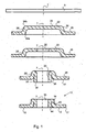
- Fig. 1 is as a starting workpiece a sheet 5 is provided, which is circular disc-shaped designed as a sheet metal blank.
- a cup 20 is formed.
- the cup 20 comprises a coaxial with a central axis 7 extending annular peripheral wall 28, which passes over a pull radius 34a in a radially to the center axis 7 outwardly projecting outer edge 26.
- a continuous, closed radial bottom 24 is formed to form a radial inner edge 22.
- the peripheral wall 28 merges with a drawing radius 34b into the radial bottom 24.
- a center opening 25 is punched into the bottom 24, wherein the intended for further forming radial inner edge 22 remains.
- This is axially transferred in a further press or deep drawing step and thereby placed in contact with the axial peripheral wall 28.
- This axial folding takes place in such a way that the turned-over inner edge 22, defined with a projection 32, projects axially with respect to the radial outer edge 26 and its lower plane 17.
- This projecting free end 30 is axially back-plunged onto the outer edge 26 in a subsequent pressing step in the axial direction, whereby a free space 36 existing at the drawing radius 34a is filled by the compressed material 44.
- a rotationally symmetrical angle ring 10 is formed with a thickened, sleeve-shaped hub portion 14 and a radially outwardly projecting, circular disk-shaped disc portion 12.
- the sleeve-shaped hub portion 14 surrounds a central center opening 15. Between the peripheral wall 28 and the axially folded inner edge 22, a gap 40 is formed, which is sealed by the compressed compressed material 44.
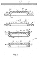
- Fig. 2 a further variant of the method is shown, wherein the three first method steps of punching a sheet 5, the deep-drawing of a cup 20 and the punching out of a central region 25 for forming a radial inner edge 22 according to the method Fig. 1 correspond.
- a modification of the previous method is according to Fig. 2 the radially outwardly projecting outer edge 26 axially folded and applied to the outside of the peripheral wall 28.
- the axial folding takes place on a press such that a free edge 30 of the outer edge 26 protrudes axially with respect to the inner edge 22 with a projection 32.
- the free end 30 is pressed towards the radially inner edge 22, wherein compressed material 44 in the region of the drawing radius 34 b at the radial Inner edge 22 is displaced and fills the space 34b.
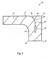
- FIG. 3 a partial area of an angle ring 10 according to the invention is shown in half section.
- the angle ring 10 comprises an axially extending, sleeve-shaped hub portion 14 and a radially outwardly extending therefrom disc portion 12.
- This angle ring is substantially according to the method according to Fig. 1 produced. It can be seen that a gap 40 is formed between the peripheral wall 28 and the turned-over inner edge 22, along which the peripheral wall 28 and the turned-over inner edge 22 substantially contact.
- a sealing region 46 of the joint 40 is formed. In the sealing region 46, the two free surfaces of the peripheral wall 28 and the folded edge are close together and are pressed so that a liquid entry into the joint 40 is prevented from the outside.
- a gap in the range of a few hundredths or tenths of a millimeter may remain, which serves to receive an oil.
- the oil can be the drawing oil used in drawing or a corrosion protection oil applied specially before sealing.
- angle ring according to the invention was previously described with reference to a rotationally symmetric part.
- other shapes in particular a square contour or other polygonal or non-circular, in particular oval shapes are possible.
Landscapes
- Engineering & Computer Science (AREA)
- Mechanical Engineering (AREA)
- Shaping Metal By Deep-Drawing, Or The Like (AREA)
- Forging (AREA)
Description
- Die Erfindung betrifft ein Verfahren zum Herstellen eines Winkelringes aus einem Blech, wobei der Winkelring einen radialen Scheibenabschnitt und einen axialen Nabenabschnitt aufweist.
- Weiter betrifft die Erfindung einen Winkelring, welcher aus einem Blech gefertigt ist und einen radialen Scheibenabschnitt und einen axialen Nabenabschnitt aufweist.
- Aus der Patentschrift
DE 10 2006 031 536 B3 der Anmelderin ist ein gattungsgemäßer Stand der Technik bekannt. Zur Herstellung einer ringförmigen Lagerscheibe wird ein Außenrand einer Blechronde axial hochgestellt und anschließend in Richtung auf den verbliebenen Bodenbereich rückgestaucht. Hierbei entsteht im Eckbereich zwischen dem Boden und dem hochgestellten Rand eine Falzfuge, welche jedoch für bestimmte Belastungsarten unerwünscht ist. Zudem weist der Scheibenabschnitt die gleiche Wandstärke wie der Nabenabschnitt auf. Die Wandstärke entspricht der Blechdicke. - Weiterhin ist es bekannt, Winkelringe spanabhebend durch Drehen aus scheibenförmigen Rohlingen herzustellen. Bei diesen spanabhebenden Verfahren entsteht jedoch fertigungsbedingt ein relativ hoher Materialabfall. Zudem ist das Drehen aufgrund der notwendigen Spannbewegungen und des Verschleißes an den Drehmeißeln relativ kostenaufwendig.
- Bei größeren Stückzahlen ist es bekannt, derartige Winkelringe in einem Schmiedeverfahren oder einem Gussverfahren herzustellen. Aufgrund der notwendigen Aufheizung des Materiales sind diese Verfahren energieaufwändig. Zudem kann beim Erkalten Wärmeverzug auftreten, was eine Nachbearbeitung des Werkstückes notwendig macht.
- Der Erfindung liegt die Aufgabe zugrunde, einen Winkelring und ein Verfahren zur Herstellung des Winkelringes anzugeben, welcher mit großer Formenvielfalt effizient und formgenau herstellbar ist.
- Die Aufgabe wird zum einen durch ein Verfahren mit den Merkmalen des Anspruchs 1 sowie durch einen Winkelring mit den Merkmalen des Anspruchs 11 gelöst. Bevorzugte Ausführungsformen der Erfindung sind in den jeweils abhängigen Ansprüchen angegeben.
- Das erfindungsgemäße Verfahren zur Herstellung eines Winkelringes aus einem Blech ist dadurch gekennzeichnet,
- dass das Blech zu einem Napf geformt wird, welcher einen radialen Innenrand, einen radialen Außenrand und eine dazwischen liegende, sich axial erstreckende Umfangswand aufweist, welche mit einem Ziehradius in den Innenrand beziehungsweise den Außenrand übergeht,
- dass der radiale Innenrand oder der radiale Außenrand axial umgelegt und an die axiale Umfangswand angelegt wird, wobei ein freies Ende des umgelegten Randes axial gegenüber der Umfangswand mit einem Überstand vorsteht, und
- dass das freie Ende des umgelegten Randes axial rückgestaucht wird, wobei ein Freiraum an zumindest einem Ziehradius der Umfangswand ausgefüllt wird.
- Ein erster Grundgedanke der Erfindung liegt darin, einen Napf aus einem Blechstück tiefzuziehen, so dass eine durch Tiefziehen sich axial erstreckende Umfangswand gebildet ist, welche an ihrem einen Ende in einen radialen Außenrand und an ihrem anderen Ende in einen radialen Innenrand übergeht. Vorzugsweise kann der Napf einen durchgehenden Boden aufweisen, in welchem dann zum Bilden des eigentlichen Innenrandes eine Mittenöffnung eingestanzt wird. Im Querschnitt weist der so hergestellte Ringkörper ein Z-Profil auf.
- Zum Bilden des axialen Nabenabschnitts wird ein radialer Rand, also der Innenrand und/oder der Außenrand axial umgelegt und in engen Kontakt an die axiale Umfangswand gebracht. Auf diese Weise entsteht eine Materialverdickung, insbesondere eine Aufdoppelung im axialen Nabenabschnitt gegenüber der ursprünglichen Wandstärke des Bleches.
- Gemäß einem weiteren Aspekt der Erfindung ist vorgesehen, dass ein freies Ende des umgelegten Randes axial gegenüber der Umfangswand definiert vorsteht. Der vorstehende Überstand wird anschließend axial rückgestaucht, wobei gestauchtes Material des freien Endes des Randes in den Bereich an einen Ziehradius der Umfangswand verdrängt wird und diesen zumindest teilweise verfüllt. Gleichzeitig kann hierbei eine innige Verbindung zwischen der axialen Umfangswand und dem angelegten Rand entlang der Kontaktfuge erreicht werden. Insgesamt kann so ein kompakter, nahezu massiver Winkelring mit einem radialen Scheibenabschnitt und einem hiervon axial vorstehenden verdickten Nabenabschnitt spanlos hergestellt werden. Insbesondere kann die Herstellung durch Kaltumformen auf einer Presse hergestellt werden. Dies ist effizient, energiesparend und sehr formgenau.
- Nach einer bevorzugten Ausführungsform der Erfindung ist vorgesehen, dass beim axialen Rückstauchen eine Fuge zwischen der axialen Umfangswand und dem angelegten Rand fluiddicht verschlossen wird. Hierbei kann der Verschluss der Fuge über die gesamte Fugenlänge oder nur in einem oberen Bereich vorgesehen werden. Ein dichtes Anpressen des angelegten Randes an die axiale Umfangswand führt zu einem hochfesten Nabenabschnitt und verhindert zudem das Eindringen von Schmutz oder Flüssigkeiten in den Fugenbereich.
- Dabei ist es nach der Erfindung vorteilhaft, dass in der Fuge Öl eingeschlossen wird. Dieses Öl, welches ein Ziehöl aus dem Umformvorgang oder ein speziell aufgetragenes. Öl, insbesondere ein Antikorrosionsöl, sein kann, vermindert eine Korrosionsgefahr innerhalb der Fuge. Weiter wird hierdurch zusätzlich einem Eindringen von Flüssigkeit in einen möglichen Freiraum aufgrund eines Kapillardruckes in die Fuge vorgebeugt. Zudem wird durch das fluiddichte Verschließen eines Randbereiches der Fuge sichergestellt, dass kein Öl aus dem Inneren der Fuge austritt, so dass der Winkelring problemlos lackiert oder oberflächenbeschichtet werden kann.
- Ein besonders zweckmäßige Gestaltung des Winkelringes wird dadurch erreicht, dass das rückgestauchte frei Ende in einer radialen Ebene des Scheibenabschnittes des Winkelringes liegt. Es wird also eine ebene Auflagefläche des Scheibenabschnittes erreicht.
- Eine weitere vorteilhafte Ausgestaltung der Erfindung liegt darin, dass beim Rückstauchen Kantenbereiche des Nabenabschnittes eckig ausgebildet werden. Insbesondere können die für das Tiefziehen notwendigen Ziehradien durch das Rückstauchen umgeformt werden, so dass sich eckige Kantenbereiche ergeben. Hierdurch kann eine besonders kompakte Bauform des Winkelringes erzielt werden. Zudem werden die Kantenbereiche zusätzlich kalt verfestigt, was das Verschleißverhalten verbessert.
- Eine weitere bevorzugte Verfahrensvariante besteht darin, dass eine Materialstärke des Nabenabschnittes doppelt so groß wie die Materialstärke des Scheibenabschnittes ausgebildet wird, welche einer Wandstärke des Blechs entspricht. Die Materialstärke des Scheibenabschnittes entspricht also der Ausgangswandstärke des Blechs, während der Nabenabschnitt gegenüber der ursprünglichen Blechstärke verdoppelt wird. Es können so also Winkelringe mit einem etwa zylindrischen massiven Nabenabschnitt gebildet werden, an welchen radial nach außen oder innen eine scheibenförmige Anlagefläche vorsteht. Das Ausgangsblech weist eine gleiche Blechstärke auf und ist insbesondere aus einem Umformstahl gebildet.
- Bevorzugt wird der Winkelring rotationssymmetrisch mit einem zylindrischen Nabenabschnitt und einem kreisförmigen Scheibenabschnitt ausgebildet. Es sind jedoch auch eckige und sonstige nicht rotationssymmetrische Formen, etwa Oval- oder Polygonformen, ohne weiteres möglich.
- Dabei ist es nach einer weiteren Variante der Erfindung vorgesehen, dass der Außenrand oder der Innenrand zum Bilden des Scheibenabschnittes besäumt, insbesondere durch Stanzen fertig gestellt wird. Ein freier Randbereich des Scheibenabschnittes kann auf diese Weise nahezu beliebig konturiert werden.
- Grundsätzlich ist es nach der Erfindung möglich, dass eine nahezu geschlossene, durchgehende Oberfläche an der Oberseite des Scheibenabschnittes gebildet wird, in welcher die Fuge zwischen der axialen Umfangswand und dem angelegten Rand kaum merklich ist. Zur Vermeidung einer Überpressung und von Übermaßen ist es nach der Erfindung bevorzugt, dass die Fuge an einer Oberseite des Scheibenabschnitts in eine ringförmige Nut mündet. Diese Nut kann Maßabweichungen kompensieren.
- Weiter ist es nach einer Variante der Erfindung vorteilhaft, dass der Winkelring anschließend oberflächenbehandelt, insbesondere lackiert oder beschichtet wird. Durch eine derartige Beschichtung kann der Fugenbereich zusätzlich versiegelt werde
- Weiterhin ist es nach einer bevorzugten Verfahrensform der Erfindung vorgesehen, dass zum Bilden des verdickten Nabenabschnittes der radiale Außenrand oder der radiale Innenrand axial umgelegt wird. Auf diese Weise kann also ein Winkelring gebildet werden, welcher einen axialen Nabenabschnitt aufweist, an welchem der Scheibenabschnitt radial nach innen oder radial nach außen vorsteht.
- Die eingangs genannte Aufgabe wird des Weiteren durch einen Winkelring gelöst, welcher dadurch gekennzeichnet ist, dass der Nabenabschnitt durch Tiefzeihen einer axialen Umfangswand und axiales Umlegen eines freien Randes des Blechs an die Umfangswand gebildet und verdickt ist, wobei zwischen der Umfangswand und dem umgelegten Rand eine Fuge gebildet ist. Dieser Winkelring kann insbesondere nach einem der vorbeschriebenen Verfahren und insbesondere nach einem der Verfahrensansprüche hergestellt sein. Es ergeben sich die zuvor beschriebenen Vorteile.
- Insbesondere liegt eine bevorzugte Ausführungsform des Winkelringes darin, dass die Fuge fluiddicht verschlossen ist. Hierdurch wird dem Eindringen von korrosiven Partikeln und Flüssigkeiten in die Fuge vorgebeugt.
- Eine weitere bevorzugte Ausführungsform des Winkelringes besteht darin, dass sich in der Fuge Öl befindet. Dieses Öl wirkt einem Eintreten von korrosiven Flüssigkeiten zusätzlich entgegen und verhindert durch eine Beschichtung der Oberfläche Korrosionsvorgänge. Das Öl in der Fuge kann insbesondere ein dünner Ölfilm auf der Blechoberfläche innerhalb eines unteren Fugenbereiches sein.
- Eine besonders stabile Ausgestaltung des Winkelringes wird in vorteilhafter Weise dadurch erreicht, dass die Fuge in einer ringförmigen Nut an einer Oberseite des Scheibenabschnittes mündet. Die Nut ist insbesondere kreisringförmig ausgebildet.
- Die Erfindung wird nachfolgend anhand von bevorzugten Ausführungsbeispielen weiter erläutert, welche stark schematisiert in den beiliegenden Zeichnungen dargestellt sind. In den Zeichnungen zeigen:
- Fig.1:
- eine schematische Ablaufskizze bei der Herstellung eines ersten Winketringes nach der Erfindung;
- Fig.2:
- eine schematische Ablaufskizze bei der erfindungsgemäßen Herstellung eines zweiten Winkelringes; und
- Fig.3:
- eine vergrößerte ausschnittsweise Querschnittsansicht eines erfindungsgemäß hergestellten dritten Winkelringes.
- Gemäß einer ersten Verfahrensvariante nach der Erfindung nach
Fig. 1 ist als Ausgangswerkstück ein Blech 5 vorgesehen, welches kreisscheibenförmig als Blechronde ausgebildet ist. In einem oder mehreren Tiefziehschritten wird ein Napf 20 gebildet. Der Napf 20 umfasst eine sich koaxial zu einer Mittenachse 7 erstreckende ringförmige Umfangswand 28, welche über einen Ziehradius 34a in einen radial zur Mittenachse 7 nach außen vorstehenden Außenrand 26 übergeht. Am anderen Ende der axialen Umfangswand 28 ist zum Bilden eines radialen Innenrandes 22 ein durchgehender, geschlossener radialer Boden 24 ausgeformt. Die Umfangswand 28 geht mit einem Ziehradius 34b in den radialen Boden 24 über. - Anschließend wird in den Boden 24 eine Mittenöffnung 25 eingestanzt, wobei der zur weiteren Umformung vorgesehene radiale Innenrand 22 verbleibt. Dieser wird in einem weiteren Pressen- oder Tiefziehschritt axial umgelegt und dabei in Kontakt an die axiale Umfangswand 28 angelegt. Dieses axiale Umlegen erfolgt derart, dass der umgelegte Innenrand 22 definiert mit einem Überstand 32 gegenüber dem radialen Außenrand 26 und ihrer unteren Ebene 17 axial vorsteht. Dieses vorstehende freie Ende 30 wird in einem anschließenden Pressenschritt in axialer Richtung auf den Außenrand 26 axial rückgestaucht, wobei ein am Ziehradius 34a bestehender Freiraum 36 durch das gestauchte Material 44 ausgefüllt wird.
- Auf diese Weise wird ein rotationssymmetrischer Winkelring 10 mit einem verdickten, hülsenförmigen Nabenabschnitt 14 und einer hiervon radial nach außen vorstehenden, kreisscheibenförmigen Scheibenabschnitt 12 gebildet. Der hülsenförmige Nabenabschnitt 14 umgibt eine zentrische Mittenöffnung 15. Zwischen der Umfangswand 28 und dem axial umgelegten Innenrand 22 ist eine Fuge 40 gebildet, welche durch das angepresste gestauchte Material 44 dicht verschlossen ist.
- Gemäß
Fig. 2 ist eine weitere Verfahrensvariante dargestellt, wobei die drei ersten Verfahrensschritte des Ausstanzens eines Bleches 5, das Tiefziehen eines Napfes 20 und das Ausstanzen eines Mittenbereiches 25 zum Bilden eines radialen Innenrandes 22 dem Verfahren nachFig. 1 entsprechen. - In Abwandlung des vorausgegangenen Verfahrens wird gemäß
Fig. 2 der radial nach außen vorstehende Außenrand 26 axial umgelegt und an die Außenseite der Umfangswand 28 angelegt. Auch hierbei erfolgt das axiale Umlegen auf einer Presse derart, dass ein freier Rand 30 des Außenrandes 26 mit einem Überstand 32 axial gegenüber dem Innenrand 22 vorsteht. Zu einem dichten Verschließen der Kontaktfuge 40 zwischen der axialen Umfangswand 28 und dem axial umgelegten Außenrand 26 wird das freie Ende 30 in Richtung auf den radialen Innenrand 22 gepresst, wobei gestauchtes Material 44 zum Bilden einer ebenen Oberseite 16 in den Bereich des Ziehradius 34b am radialen Innenrand 22 verdrängt wird und den Freiraum 34b ausfüllt. - In der schematischen ausschnittsweisen Ansicht von
Fig. 3 wird ein Teilbereich eines erfindungsgemäßen Winkelringes 10 im Halbschnitt gezeigt. Der Winkelring 10 umfasst einen sich axial erstreckenden, hülsenförmigen Nabenabschnitt 14 und einen sich hiervon radial nach außen erstreckenden Scheibenabschnitt 12. Dieser Winkelring ist im Wesentlichen nach dem Verfahren gemäßFig. 1 hergestellt. Es ist zu erkennen, dass zwischen der Umfangswand 28 und dem umgelegten Innenrand 22 eine Fuge 40 ausgebildet ist, entlang welcher sich die Umfangswand 28 und der umgelegte Innenrand 22 im Wesentlichen kontaktieren. Durch das beim Rückstauchen verdrängte, gestauchte Material 44 wird ein Dichtbereich 46 der Fuge 40 gebildet. Im Dichtbereich 46 liegen die beiden freien Oberflächen der Umfangswand 28 und des umgelegten Randes dicht aneinander und sind derart verpresst, dass ein Flüssigkeitseintritt in die Fuge 40 von außen verhindert ist. - In einem vom Dichtbereich 46 abgewandten Aufnahmebereich 48 der Fuge 40 kann ein Spalt im Bereich von einigen Hundertstel oder Zehntel Millimeter verbleiben, welcher zur Aufnahme eines Öles dient. Bei dem Öl kann es sich um das beim Ziehen eingesetzte Ziehöl oder ein speziell vor dem Verschließen aufgebrachtes Korrosionsschutzöl handeln. Durch den Dichtbereich 46 ist sichergestellt, dass eingeschossenes Öl aus dem Aufnahmebereich 48 nicht nach außen treten kann.
- Zur Oberseite 16 des Scheibenabschnittes 12 hin mündet die Fuge 40 in eine ringförmige, im Querschnitt V-förmige Nut 42. Bei dem vorliegenden Winkelring 10 wird also keine durchgehende ebene Oberseite 16 gebildet. Die Nut 42 kann so gewisse Maßschwankungen und Materialdickenschwankungen und damit überschüssiges gestauchtes Material 44 kompensieren, so dass Überpressungen vermieden werden. Des Weiteren können beim Rückstauchen neben einem dichten Verschließen der Fuge 40 Kantenbereiche 19 des Nabenabschnittes 14 eckig, das heißt mit einem kleinen Kantenradius oder einer Phase, ausgebildet werden. Hierdurch wird trotz Vorsehen von für das Umformen günstiger Ziehradien eine kompakte Ausgestaltung des Winkelringes 10 mit eckigen Kantenbereichen 19 geschaffen.
- Der erfindungsgemäße Winkelring wurde vorausgehend anhand eines rotationssymmetrischen Teiles beschrieben. Es sind jedoch auch andere Formgebungen, insbesondere eine quadratische Kontur oder sonstige polygonale oder unrunde, insbesondere ovale Formen möglich.
Claims (14)
- Verfahren zum Herstellen eines Winkelringes (10) aus einem Blech (5), wobei der Winkelring (10) einen radialen Scheibenabschnitt (12) und einen axialen Nabenabschnitt (14) aufweist,
dadurch gekennzeichnet,- dass das Blech (5) zu einem Napf (20) geformt wird, welcher einen radialen Innenrand (22), einen radialen Außenrand (26) und eine dazwischen liegende, sich axial erstreckende Umfangswand (28) aufweist, welche mit einem Ziehradius (34) in den Innenrand (22) beziehungsweise den Außenrand (26) übergeht,- dass zum Bilden eines verdickten Nabenabschnittes (14) der radiale Innenrand (22) oder der radiale Außenrand (26) axial umgelegt und an die axiale Umfangswand (28) angelegt wird, wobei ein freies Ende (30) des umgelegten Randes (22; 26) axial gegenüber der Umfangswand (28) mit einem Überstand (32) vorsteht, und- dass das freie Ende (30) des umgelegten Randes (22; 26) axial rückgestaucht wird, wobei ein Freiraum (36) an zumindest einem Ziehradius (34) der Umfangswand (28) ausgefüllt wird. - Verfahren nach Anspruch 1,
dadurch gekennzeichnet,
dass beim axialen Rückstauchen eine Fuge (40) zwischen der axialen Umfangswand (28) und dem angelegten Rand (22; 26) fluiddicht verschlossen wird. - Verfahren nach Anspruch 2,
dadurch gekennzeichnet,
dass in der Fuge (40) Öl eingeschlossen wird. - Verfahren nach einem der Ansprüche 1 bis 3,
dadurch gekennzeichnet,
dass zum Bilden des radialen Innenrandes (22) der Napf (20) mit einem durchgehenden Boden (24) tiefgezogen wird, dessen Mittenbereich (25) ausgestanzt wird. - Verfahren nach einem der Ansprüche 1 bis 4,
dadurch gekennzeichnet
dass das rückgestauchte freie Ende (30) in einer Ebene (17) des Scheibenabschnittes (12) des Winkelringes liegt. - Verfahren nach einem der Ansprüche 1 bis 5,
dadurch gekennzeichnet,
dass beim Rückstauchen Kantenbereiche (19) des Nabenabschnittes (14) eckig ausgebildet werden. - Verfahren nach einem der Ansprüche 1 bis 6,
dadurch gekennzeichnet,
dass eine Materialstärke des Nabenabschnittes (14) doppelt so groß wie die Materialstärke des Scheibenabschnittes (12) ausgebildet wird, welche einer Wandstärke des Blechs (5) entspricht. - Verfahren nach einem der Ansprüche 1 bis 7,
dadurch gekennzeichnet,
dass der Außenrand (26) oder der Innenrand (22) zum Bilden des Scheibenabschnittes (12) besäumt, insbesondere durch Stanzen, fertig gestellt wird. - Verfahren nach einem der Ansprüche 5 bis 8,
dadurch gekennzeichnet,
dass die Fuge (40) an einer Oberseite (16) des Scheibenabschnittes (12) in eine ringförmige Nut (42) mündet. - Verfahren nach einem der Ansprüche 1 bis 9,
dadurch gekennzeichnet,
dass der Winkelring (10) anschließend oberflächenbehandelt, insbesondere lackiert oder beschichtet wird. - Winkelring, welcher aus einem Blech (5) gefertigt ist und einen radialen Scheibenabschnitt (12) und einen axialen Nabenabschnitt (14) aufweist,
dadurch gekennzeichnet,
dass der Nabenabschnitt (14) durch Tiefziehen eines Napfes (20) mit axialer Umfangswand (28) und axiales Umlegen eines Randes (22; 26) des Napfes (20) an die Umfangswand gebildet und gegenüber dem Scheibenabschnitt (12) verdickt ist, wobei zwischen der Umfangswand (28) und dem umgelegten Rand (22; 26) eine Fuge (40) gebildet ist. - Winkelring nach Anspruch 11,
dadurch gekennzeichnet,
dass die Fuge (40) fluiddicht verschlossen ist. - Winkelring nach Anspruch 12,
dadurch gekennzeichnet,
dass sich in der Fuge (40) Öl befindet. - Winkelring nach einem der Ansprüche 11 bis 13,
dadurch gekennzeichnet
dass die Fuge (40) in einer ringförmigen Nut (42) an einer Oberseite (16) des Scheibenabschnittes (12) mündet.
Priority Applications (1)
| Application Number | Priority Date | Filing Date | Title |
|---|---|---|---|
| EP20120005212 EP2687301B1 (de) | 2012-07-16 | 2012-07-16 | Winkelring und Verfahren zu dessen Herstellung |
Applications Claiming Priority (1)
| Application Number | Priority Date | Filing Date | Title |
|---|---|---|---|
| EP20120005212 EP2687301B1 (de) | 2012-07-16 | 2012-07-16 | Winkelring und Verfahren zu dessen Herstellung |
Publications (2)
| Publication Number | Publication Date |
|---|---|
| EP2687301A1 EP2687301A1 (de) | 2014-01-22 |
| EP2687301B1 true EP2687301B1 (de) | 2014-09-10 |
Family
ID=46639268
Family Applications (1)
| Application Number | Title | Priority Date | Filing Date |
|---|---|---|---|
| EP20120005212 Active EP2687301B1 (de) | 2012-07-16 | 2012-07-16 | Winkelring und Verfahren zu dessen Herstellung |
Country Status (1)
| Country | Link |
|---|---|
| EP (1) | EP2687301B1 (de) |
Families Citing this family (1)
| Publication number | Priority date | Publication date | Assignee | Title |
|---|---|---|---|---|
| CN111940601B (zh) * | 2020-08-19 | 2022-06-07 | 裕钦精密拉深技术(苏州)有限公司 | 导向套多工位模具及其使用方法 |
Family Cites Families (4)
| Publication number | Priority date | Publication date | Assignee | Title |
|---|---|---|---|---|
| DE4119860A1 (de) * | 1991-06-17 | 1992-12-24 | Skf Gmbh | Lagerbuechse, insbesondere fuer kreuzgelenke, sowie verfahren zur herstellung derselben |
| DE4294681C2 (de) * | 1992-01-10 | 1997-07-24 | Kanemitsu Akashi Kk | Verfahren zum Formen einer Nabe in einem platten- oder scheibenförmigen Metallrohling |
| DE10020176C2 (de) * | 2000-04-25 | 2003-10-09 | Fischer & Kaufmann Gmbh & Co K | Verfahren zur Herstellung einer Scheibe mit einer verdickten Nabe durch Tiefziehen |
| DE102006031536B3 (de) | 2006-07-07 | 2007-10-18 | Fischer & Kaufmann Gmbh & Co. Kg | Lagerscheibe und Verfahren zu deren Herstellung |
-
2012
- 2012-07-16 EP EP20120005212 patent/EP2687301B1/de active Active
Also Published As
| Publication number | Publication date |
|---|---|
| EP2687301A1 (de) | 2014-01-22 |
Similar Documents
| Publication | Publication Date | Title |
|---|---|---|
| EP2449272B1 (de) | Sicherungsmutter | |
| EP0355647A2 (de) | Spundbehälter | |
| EP3409392B1 (de) | Verfahren zur herstellung von stanzteilen | |
| DE112007000239T5 (de) | Verfahren zum Herstellen einer Radschüssel | |
| DE112007000192T5 (de) | Verfahren zum Herstellen einer Radscheibe | |
| EP2433034A1 (de) | Verfahren zur herstellung metallischer elemente, insbesondere dichtelemente | |
| DE4006582C2 (de) | Verfahren zum Herstellen eines ringförmigen Zahnrades aus einer Metallplatte | |
| DE2460185A1 (de) | Verfahren zur herstellung von dichtungselementen mit hydrodynamischer wirkung | |
| DE102015211857A1 (de) | Lagerring, Verfahren zur Herstellung eines solchen Rings und Lager, das einen solchen Ring enthält | |
| DE102004022666A1 (de) | Stanzverfahren | |
| EP1225375A2 (de) | Schaltwalze eines Wechselgetriebes | |
| EP2687301B1 (de) | Winkelring und Verfahren zu dessen Herstellung | |
| DE2624872C3 (de) | Verfahren zum Herstellen von ungeteilten Felgen | |
| DE10322752B4 (de) | Verfahren zum Herstellen von Werkstücken aus Blech | |
| EP3293404A1 (de) | Kunststoffkappe und anordnung mit einer solchen kunststoffkappe | |
| DE4332306A1 (de) | Verfahren zur Herstellung eines leicht zu öffnenden Dosendeckels aus Blech | |
| CH417376A (de) | Verfahren zum Befestigen eines mit mindestens einer Öffnung versehenen Aufreisslappens an einem Wandteil eines Metallbehälters, gemäss diesem Verfahren hergestellter Metallbehälter und Pressanlage zur Durchführung des Verfahrens | |
| WO2008034564A1 (de) | Verfahren zur herstellung einer radschüssel | |
| DE102005028093B3 (de) | Verfahren zur gleichzeitigen Herstellung eines Kegelrollenlagerinnenrings und eines Kegelrollenlageraußenrings | |
| EP3880977B1 (de) | Vollstanzniet | |
| EP1591676B1 (de) | Einpressmutter | |
| DE102006031536B3 (de) | Lagerscheibe und Verfahren zu deren Herstellung | |
| DE10061403B4 (de) | Verfahren zur Herstellung eines rotationssymmetrischen Formkörpers | |
| DE19714982C2 (de) | Verfahren zur Herstellung eines Verschlußringes mit einer umlaufenden Siegelfläche zum Aufsiegeln einer Verschlußmembran und einem Bördelrand zum Aufbringen des Verschlußringes auf den Rand eines Gebindes sowie nach dem Verfahren hergestellter Ring | |
| CH711319A2 (de) | Herstellungsverfahren für eine Verbundbremsscheibe sowie entsprechende Verbundbremsscheibe. |
Legal Events
| Date | Code | Title | Description |
|---|---|---|---|
| PUAI | Public reference made under article 153(3) epc to a published international application that has entered the european phase |
Free format text: ORIGINAL CODE: 0009012 |
|
| 17P | Request for examination filed |
Effective date: 20130227 |
|
| AK | Designated contracting states |
Kind code of ref document: A1 Designated state(s): AL AT BE BG CH CY CZ DE DK EE ES FI FR GB GR HR HU IE IS IT LI LT LU LV MC MK MT NL NO PL PT RO RS SE SI SK SM TR |
|
| AX | Request for extension of the european patent |
Extension state: BA ME |
|
| GRAP | Despatch of communication of intention to grant a patent |
Free format text: ORIGINAL CODE: EPIDOSNIGR1 |
|
| RIC1 | Information provided on ipc code assigned before grant |
Ipc: B21H 1/06 20060101ALI20140210BHEP Ipc: B21D 53/10 20060101AFI20140210BHEP Ipc: B21D 53/20 20060101ALI20140210BHEP Ipc: B21K 1/40 20060101ALI20140210BHEP Ipc: F16C 33/58 20060101ALI20140210BHEP |
|
| INTG | Intention to grant announced |
Effective date: 20140314 |
|
| GRAS | Grant fee paid |
Free format text: ORIGINAL CODE: EPIDOSNIGR3 |
|
| GRAA | (expected) grant |
Free format text: ORIGINAL CODE: 0009210 |
|
| AK | Designated contracting states |
Kind code of ref document: B1 Designated state(s): AL AT BE BG CH CY CZ DE DK EE ES FI FR GB GR HR HU IE IS IT LI LT LU LV MC MK MT NL NO PL PT RO RS SE SI SK SM TR |
|
| REG | Reference to a national code |
Ref country code: GB Ref legal event code: FG4D Free format text: NOT ENGLISH |
|
| REG | Reference to a national code |
Ref country code: CH Ref legal event code: EP |
|
| REG | Reference to a national code |
Ref country code: IE Ref legal event code: FG4D Free format text: LANGUAGE OF EP DOCUMENT: GERMAN |
|
| REG | Reference to a national code |
Ref country code: AT Ref legal event code: REF Ref document number: 686389 Country of ref document: AT Kind code of ref document: T Effective date: 20141015 |
|
| REG | Reference to a national code |
Ref country code: DE Ref legal event code: R096 Ref document number: 502012001211 Country of ref document: DE Effective date: 20141023 |
|
| PG25 | Lapsed in a contracting state [announced via postgrant information from national office to epo] |
Ref country code: GR Free format text: LAPSE BECAUSE OF FAILURE TO SUBMIT A TRANSLATION OF THE DESCRIPTION OR TO PAY THE FEE WITHIN THE PRESCRIBED TIME-LIMIT Effective date: 20141211 Ref country code: NO Free format text: LAPSE BECAUSE OF FAILURE TO SUBMIT A TRANSLATION OF THE DESCRIPTION OR TO PAY THE FEE WITHIN THE PRESCRIBED TIME-LIMIT Effective date: 20141210 Ref country code: ES Free format text: LAPSE BECAUSE OF FAILURE TO SUBMIT A TRANSLATION OF THE DESCRIPTION OR TO PAY THE FEE WITHIN THE PRESCRIBED TIME-LIMIT Effective date: 20140910 Ref country code: FI Free format text: LAPSE BECAUSE OF FAILURE TO SUBMIT A TRANSLATION OF THE DESCRIPTION OR TO PAY THE FEE WITHIN THE PRESCRIBED TIME-LIMIT Effective date: 20140910 Ref country code: SE Free format text: LAPSE BECAUSE OF FAILURE TO SUBMIT A TRANSLATION OF THE DESCRIPTION OR TO PAY THE FEE WITHIN THE PRESCRIBED TIME-LIMIT Effective date: 20140910 Ref country code: LT Free format text: LAPSE BECAUSE OF FAILURE TO SUBMIT A TRANSLATION OF THE DESCRIPTION OR TO PAY THE FEE WITHIN THE PRESCRIBED TIME-LIMIT Effective date: 20140910 |
|
| REG | Reference to a national code |
Ref country code: NL Ref legal event code: VDEP Effective date: 20140910 |
|
| REG | Reference to a national code |
Ref country code: LT Ref legal event code: MG4D |
|
| PG25 | Lapsed in a contracting state [announced via postgrant information from national office to epo] |
Ref country code: CY Free format text: LAPSE BECAUSE OF FAILURE TO SUBMIT A TRANSLATION OF THE DESCRIPTION OR TO PAY THE FEE WITHIN THE PRESCRIBED TIME-LIMIT Effective date: 20140910 Ref country code: LV Free format text: LAPSE BECAUSE OF FAILURE TO SUBMIT A TRANSLATION OF THE DESCRIPTION OR TO PAY THE FEE WITHIN THE PRESCRIBED TIME-LIMIT Effective date: 20140910 Ref country code: RS Free format text: LAPSE BECAUSE OF FAILURE TO SUBMIT A TRANSLATION OF THE DESCRIPTION OR TO PAY THE FEE WITHIN THE PRESCRIBED TIME-LIMIT Effective date: 20140910 Ref country code: HR Free format text: LAPSE BECAUSE OF FAILURE TO SUBMIT A TRANSLATION OF THE DESCRIPTION OR TO PAY THE FEE WITHIN THE PRESCRIBED TIME-LIMIT Effective date: 20140910 |
|
| PG25 | Lapsed in a contracting state [announced via postgrant information from national office to epo] |
Ref country code: NL Free format text: LAPSE BECAUSE OF FAILURE TO SUBMIT A TRANSLATION OF THE DESCRIPTION OR TO PAY THE FEE WITHIN THE PRESCRIBED TIME-LIMIT Effective date: 20140910 |
|
| PG25 | Lapsed in a contracting state [announced via postgrant information from national office to epo] |
Ref country code: PT Free format text: LAPSE BECAUSE OF FAILURE TO SUBMIT A TRANSLATION OF THE DESCRIPTION OR TO PAY THE FEE WITHIN THE PRESCRIBED TIME-LIMIT Effective date: 20150112 Ref country code: SK Free format text: LAPSE BECAUSE OF FAILURE TO SUBMIT A TRANSLATION OF THE DESCRIPTION OR TO PAY THE FEE WITHIN THE PRESCRIBED TIME-LIMIT Effective date: 20140910 Ref country code: IS Free format text: LAPSE BECAUSE OF FAILURE TO SUBMIT A TRANSLATION OF THE DESCRIPTION OR TO PAY THE FEE WITHIN THE PRESCRIBED TIME-LIMIT Effective date: 20150110 Ref country code: RO Free format text: LAPSE BECAUSE OF FAILURE TO SUBMIT A TRANSLATION OF THE DESCRIPTION OR TO PAY THE FEE WITHIN THE PRESCRIBED TIME-LIMIT Effective date: 20140910 Ref country code: CZ Free format text: LAPSE BECAUSE OF FAILURE TO SUBMIT A TRANSLATION OF THE DESCRIPTION OR TO PAY THE FEE WITHIN THE PRESCRIBED TIME-LIMIT Effective date: 20140910 Ref country code: EE Free format text: LAPSE BECAUSE OF FAILURE TO SUBMIT A TRANSLATION OF THE DESCRIPTION OR TO PAY THE FEE WITHIN THE PRESCRIBED TIME-LIMIT Effective date: 20140910 |
|
| PG25 | Lapsed in a contracting state [announced via postgrant information from national office to epo] |
Ref country code: PL Free format text: LAPSE BECAUSE OF FAILURE TO SUBMIT A TRANSLATION OF THE DESCRIPTION OR TO PAY THE FEE WITHIN THE PRESCRIBED TIME-LIMIT Effective date: 20140910 |
|
| REG | Reference to a national code |
Ref country code: DE Ref legal event code: R097 Ref document number: 502012001211 Country of ref document: DE |
|
| PLBE | No opposition filed within time limit |
Free format text: ORIGINAL CODE: 0009261 |
|
| STAA | Information on the status of an ep patent application or granted ep patent |
Free format text: STATUS: NO OPPOSITION FILED WITHIN TIME LIMIT |
|
| PG25 | Lapsed in a contracting state [announced via postgrant information from national office to epo] |
Ref country code: DK Free format text: LAPSE BECAUSE OF FAILURE TO SUBMIT A TRANSLATION OF THE DESCRIPTION OR TO PAY THE FEE WITHIN THE PRESCRIBED TIME-LIMIT Effective date: 20140910 |
|
| 26N | No opposition filed |
Effective date: 20150611 |
|
| PG25 | Lapsed in a contracting state [announced via postgrant information from national office to epo] |
Ref country code: IT Free format text: LAPSE BECAUSE OF FAILURE TO SUBMIT A TRANSLATION OF THE DESCRIPTION OR TO PAY THE FEE WITHIN THE PRESCRIBED TIME-LIMIT Effective date: 20140910 |
|
| PG25 | Lapsed in a contracting state [announced via postgrant information from national office to epo] |
Ref country code: SI Free format text: LAPSE BECAUSE OF FAILURE TO SUBMIT A TRANSLATION OF THE DESCRIPTION OR TO PAY THE FEE WITHIN THE PRESCRIBED TIME-LIMIT Effective date: 20140910 |
|
| PG25 | Lapsed in a contracting state [announced via postgrant information from national office to epo] |
Ref country code: MC Free format text: LAPSE BECAUSE OF FAILURE TO SUBMIT A TRANSLATION OF THE DESCRIPTION OR TO PAY THE FEE WITHIN THE PRESCRIBED TIME-LIMIT Effective date: 20140910 |
|
| REG | Reference to a national code |
Ref country code: CH Ref legal event code: PL |
|
| PG25 | Lapsed in a contracting state [announced via postgrant information from national office to epo] |
Ref country code: LU Free format text: LAPSE BECAUSE OF FAILURE TO SUBMIT A TRANSLATION OF THE DESCRIPTION OR TO PAY THE FEE WITHIN THE PRESCRIBED TIME-LIMIT Effective date: 20150716 |
|
| REG | Reference to a national code |
Ref country code: IE Ref legal event code: MM4A |
|
| PG25 | Lapsed in a contracting state [announced via postgrant information from national office to epo] |
Ref country code: LI Free format text: LAPSE BECAUSE OF NON-PAYMENT OF DUE FEES Effective date: 20150731 Ref country code: CH Free format text: LAPSE BECAUSE OF NON-PAYMENT OF DUE FEES Effective date: 20150731 |
|
| REG | Reference to a national code |
Ref country code: FR Ref legal event code: ST Effective date: 20160331 |
|
| PG25 | Lapsed in a contracting state [announced via postgrant information from national office to epo] |
Ref country code: FR Free format text: LAPSE BECAUSE OF NON-PAYMENT OF DUE FEES Effective date: 20150731 |
|
| PG25 | Lapsed in a contracting state [announced via postgrant information from national office to epo] |
Ref country code: IE Free format text: LAPSE BECAUSE OF NON-PAYMENT OF DUE FEES Effective date: 20150716 |
|
| GBPC | Gb: european patent ceased through non-payment of renewal fee |
Effective date: 20160716 |
|
| PG25 | Lapsed in a contracting state [announced via postgrant information from national office to epo] |
Ref country code: MT Free format text: LAPSE BECAUSE OF FAILURE TO SUBMIT A TRANSLATION OF THE DESCRIPTION OR TO PAY THE FEE WITHIN THE PRESCRIBED TIME-LIMIT Effective date: 20140910 |
|
| PG25 | Lapsed in a contracting state [announced via postgrant information from national office to epo] |
Ref country code: SM Free format text: LAPSE BECAUSE OF FAILURE TO SUBMIT A TRANSLATION OF THE DESCRIPTION OR TO PAY THE FEE WITHIN THE PRESCRIBED TIME-LIMIT Effective date: 20140910 Ref country code: HU Free format text: LAPSE BECAUSE OF FAILURE TO SUBMIT A TRANSLATION OF THE DESCRIPTION OR TO PAY THE FEE WITHIN THE PRESCRIBED TIME-LIMIT; INVALID AB INITIO Effective date: 20120716 Ref country code: GB Free format text: LAPSE BECAUSE OF NON-PAYMENT OF DUE FEES Effective date: 20160716 Ref country code: BG Free format text: LAPSE BECAUSE OF FAILURE TO SUBMIT A TRANSLATION OF THE DESCRIPTION OR TO PAY THE FEE WITHIN THE PRESCRIBED TIME-LIMIT Effective date: 20140910 |
|
| PG25 | Lapsed in a contracting state [announced via postgrant information from national office to epo] |
Ref country code: BE Free format text: LAPSE BECAUSE OF NON-PAYMENT OF DUE FEES Effective date: 20150731 |
|
| REG | Reference to a national code |
Ref country code: DE Ref legal event code: R082 Ref document number: 502012001211 Country of ref document: DE Representative=s name: WUNDERLICH & HEIM PATENTANWAELTE PARTNERSCHAFT, DE |
|
| PG25 | Lapsed in a contracting state [announced via postgrant information from national office to epo] |
Ref country code: TR Free format text: LAPSE BECAUSE OF FAILURE TO SUBMIT A TRANSLATION OF THE DESCRIPTION OR TO PAY THE FEE WITHIN THE PRESCRIBED TIME-LIMIT Effective date: 20140910 Ref country code: MK Free format text: LAPSE BECAUSE OF FAILURE TO SUBMIT A TRANSLATION OF THE DESCRIPTION OR TO PAY THE FEE WITHIN THE PRESCRIBED TIME-LIMIT Effective date: 20140910 |
|
| REG | Reference to a national code |
Ref country code: AT Ref legal event code: MM01 Ref document number: 686389 Country of ref document: AT Kind code of ref document: T Effective date: 20170716 |
|
| PG25 | Lapsed in a contracting state [announced via postgrant information from national office to epo] |
Ref country code: AL Free format text: LAPSE BECAUSE OF FAILURE TO SUBMIT A TRANSLATION OF THE DESCRIPTION OR TO PAY THE FEE WITHIN THE PRESCRIBED TIME-LIMIT Effective date: 20140910 |
|
| PG25 | Lapsed in a contracting state [announced via postgrant information from national office to epo] |
Ref country code: AT Free format text: LAPSE BECAUSE OF NON-PAYMENT OF DUE FEES Effective date: 20170716 |
|
| P01 | Opt-out of the competence of the unified patent court (upc) registered |
Effective date: 20230509 |
|
| PGFP | Annual fee paid to national office [announced via postgrant information from national office to epo] |
Ref country code: DE Payment date: 20250730 Year of fee payment: 14 |