EP2687309A2 - Werkstück mit nicht drehbarer gekrümmter Oberfläche, das von einer Drehmaschine bearbeitet wird - Google Patents
Werkstück mit nicht drehbarer gekrümmter Oberfläche, das von einer Drehmaschine bearbeitet wird Download PDFInfo
- Publication number
- EP2687309A2 EP2687309A2 EP13177132.1A EP13177132A EP2687309A2 EP 2687309 A2 EP2687309 A2 EP 2687309A2 EP 13177132 A EP13177132 A EP 13177132A EP 2687309 A2 EP2687309 A2 EP 2687309A2
- Authority
- EP
- European Patent Office
- Prior art keywords
- workpiece
- cutter
- curved surface
- per minute
- lathe
- Prior art date
- Legal status (The legal status is an assumption and is not a legal conclusion. Google has not performed a legal analysis and makes no representation as to the accuracy of the status listed.)
- Ceased
Links
Images


Classifications
-
- H—ELECTRICITY
- H05—ELECTRIC TECHNIQUES NOT OTHERWISE PROVIDED FOR
- H05K—PRINTED CIRCUITS; CASINGS OR CONSTRUCTIONAL DETAILS OF ELECTRIC APPARATUS; MANUFACTURE OF ASSEMBLAGES OF ELECTRICAL COMPONENTS
- H05K5/00—Casings, cabinets or drawers for electric apparatus
- H05K5/04—Metal casings
-
- B—PERFORMING OPERATIONS; TRANSPORTING
- B23—MACHINE TOOLS; METAL-WORKING NOT OTHERWISE PROVIDED FOR
- B23B—TURNING; BORING
- B23B1/00—Methods for turning or working essentially requiring the use of turning-machines; Use of auxiliary equipment in connection with such methods
-
- B—PERFORMING OPERATIONS; TRANSPORTING
- B23—MACHINE TOOLS; METAL-WORKING NOT OTHERWISE PROVIDED FOR
- B23B—TURNING; BORING
- B23B5/00—Turning-machines or devices specially adapted for particular work; Accessories specially adapted therefor
- B23B5/36—Turning-machines or devices specially adapted for particular work; Accessories specially adapted therefor for turning specially-shaped surfaces by making use of relative movement of the tool and work produced by geometrical mechanisms, i.e. forming-lathes
-
- B—PERFORMING OPERATIONS; TRANSPORTING
- B23—MACHINE TOOLS; METAL-WORKING NOT OTHERWISE PROVIDED FOR
- B23B—TURNING; BORING
- B23B5/00—Turning-machines or devices specially adapted for particular work; Accessories specially adapted therefor
-
- B—PERFORMING OPERATIONS; TRANSPORTING
- B23—MACHINE TOOLS; METAL-WORKING NOT OTHERWISE PROVIDED FOR
- B23Q—DETAILS, COMPONENTS, OR ACCESSORIES FOR MACHINE TOOLS, e.g. ARRANGEMENTS FOR COPYING OR CONTROLLING; MACHINE TOOLS IN GENERAL CHARACTERISED BY THE CONSTRUCTION OF PARTICULAR DETAILS OR COMPONENTS; COMBINATIONS OR ASSOCIATIONS OF METAL-WORKING MACHINES, NOT DIRECTED TO A PARTICULAR RESULT
- B23Q1/00—Members which are comprised in the general build-up of a form of machine, particularly relatively large fixed members
- B23Q1/01—Frames, beds, pillars or like members; Arrangement of ways
- B23Q1/015—Frames, beds, pillars
-
- B—PERFORMING OPERATIONS; TRANSPORTING
- B23—MACHINE TOOLS; METAL-WORKING NOT OTHERWISE PROVIDED FOR
- B23Q—DETAILS, COMPONENTS, OR ACCESSORIES FOR MACHINE TOOLS, e.g. ARRANGEMENTS FOR COPYING OR CONTROLLING; MACHINE TOOLS IN GENERAL CHARACTERISED BY THE CONSTRUCTION OF PARTICULAR DETAILS OR COMPONENTS; COMBINATIONS OR ASSOCIATIONS OF METAL-WORKING MACHINES, NOT DIRECTED TO A PARTICULAR RESULT
- B23Q5/00—Driving or feeding mechanisms; Control arrangements therefor
- B23Q5/22—Feeding members carrying tools or work
-
- Y—GENERAL TAGGING OF NEW TECHNOLOGICAL DEVELOPMENTS; GENERAL TAGGING OF CROSS-SECTIONAL TECHNOLOGIES SPANNING OVER SEVERAL SECTIONS OF THE IPC; TECHNICAL SUBJECTS COVERED BY FORMER USPC CROSS-REFERENCE ART COLLECTIONS [XRACs] AND DIGESTS
- Y10—TECHNICAL SUBJECTS COVERED BY FORMER USPC
- Y10T—TECHNICAL SUBJECTS COVERED BY FORMER US CLASSIFICATION
- Y10T428/00—Stock material or miscellaneous articles
- Y10T428/12—All metal or with adjacent metals
- Y10T428/1241—Nonplanar uniform thickness or nonlinear uniform diameter [e.g., L-shape]
-
- Y—GENERAL TAGGING OF NEW TECHNOLOGICAL DEVELOPMENTS; GENERAL TAGGING OF CROSS-SECTIONAL TECHNOLOGIES SPANNING OVER SEVERAL SECTIONS OF THE IPC; TECHNICAL SUBJECTS COVERED BY FORMER USPC CROSS-REFERENCE ART COLLECTIONS [XRACs] AND DIGESTS
- Y10—TECHNICAL SUBJECTS COVERED BY FORMER USPC
- Y10T—TECHNICAL SUBJECTS COVERED BY FORMER US CLASSIFICATION
- Y10T428/00—Stock material or miscellaneous articles
- Y10T428/13—Hollow or container type article [e.g., tube, vase, etc.]
-
- Y—GENERAL TAGGING OF NEW TECHNOLOGICAL DEVELOPMENTS; GENERAL TAGGING OF CROSS-SECTIONAL TECHNOLOGIES SPANNING OVER SEVERAL SECTIONS OF THE IPC; TECHNICAL SUBJECTS COVERED BY FORMER USPC CROSS-REFERENCE ART COLLECTIONS [XRACs] AND DIGESTS
- Y10—TECHNICAL SUBJECTS COVERED BY FORMER USPC
- Y10T—TECHNICAL SUBJECTS COVERED BY FORMER US CLASSIFICATION
- Y10T428/00—Stock material or miscellaneous articles
- Y10T428/24—Structurally defined web or sheet [e.g., overall dimension, etc.]
- Y10T428/24628—Nonplanar uniform thickness material
Definitions
- the present disclosure generally relates to workpieces, and particularly, to a workpiece having a non-rotary curved surface machined by lathe.
- FIG. 8 shows a magnified photo of a workpiece having a non-rotary curved surface which is machined after a conventional milling process.
- a milling cutter with different cutting edges is used for machining curved surfaces.
- Some tracks are formed on the milled surface of a workpiece because of intermitted contact and interrupted milling by the milling cutter.
- the average milled surface roughness of the workpiece shown in FIG. 8 is 5 microns.
- a polish process needs to be added for a better appearance.
- a workpiece has non-rotary curved surface and edges.
- the workpiece is machined by a lathe.
- the lathe includes a cutter and a work table under the cutter.
- the worktable is configured for driving the workpiece to rotate.
- the non-rotary curved surface of the workpiece has a good finish because the cutter moves along a spiral cutting path on the workpiece at high speed continuously during the machining.
- FIG. 1 is an isometric view of an embodiment of a lathe having a cutter.
- FIG. 2 is an isometric and partial view of the lathe of FIG. 1 .
- FIG. 3 is an isometric and exploded view of the lathe of FIG. 2 .
- FIG. 4 is an isometric view of a workpiece having a curved surface machined by the lathe of FIG.1 .
- FIG. 5 a sectional view of the workpiece of the FIG. 4 along a direction VI -VI.
- FIG. 6 is a top plan view of a planar cutting path of the cutter machining the workpiece of FIG. 1 .
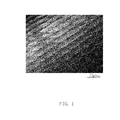
- FIG. 7 is a magnified photo of the workpiece of the FIG. 4 .
- FIG. 8 is a magnified photo of a workpiece having non-rotary curved surfaces machined by conventional milling process.
- FIGS. 1 to 3 show an embodiment of a lathe 200.
- the lathe 200 is used for machining curved surface on a workpiece 300 in a single operation.
- the lathe 200 includes a machine support 10, a rotating driver 20, a work table 30, two cross beams 50, four driving mechanisms 60, and a feeding device 70.
- the work table 30 holds the workpiece 300 in place, and is supported by the machine support 10.
- the cross beams 50 are slidably positioned on the machine support 10 above the work table 30.
- the feeding device 70 is slidably assembled between the cross beams 50.
- the feeding device 40 can be driven to move along the three axes, X, Y, and Z.
- the machine support 10 includes a base 12 and a pair of support bodies 14 positioned substantially parallel to each other on the base 12.
- Two spaced first sliding rails 142 are positioned in parallel on a surface of each support body 13 away from the base 12.
- the first sliding rails 142 extend substantially parallel to the Y-axis.
- a first receiving groove 144 is formed on each support body 13 between the corresponding two first sliding rails 142.
- the work table 30 is substantially cylindrical, and rotatably positioned on the base 12 via a rotating driver 20 between the two support bodies 14.
- the rotating driver 20 is a direct drive motor.
- Two cross beams 50 are oppositely slidably positioned on the support bodies 13 and extend substantially parallel to the X-axis to provide high stability. In the illustrated embodiment, opposite ends of each of the cross beams 50 respectively slidably engage with a corresponding pair of the first sliding rails 142.
- Each cross beam 50 includes a support portion 52 and two fixing portions 54 positioned at opposite ends of the support portion 52.
- a sliding surface 522 is positioned on the support portion 52.
- Two spaced second sliding rails 5222 are positioned on each sliding surface 522 and extend substantially parallel to the X-axis.
- a second receiving groove 5224 is formed on each sliding surface 522 between the two second sliding rails 5222. Two sliding surfaces 522 are positioned face to face and substantially perpendicular to the work table 30.
- the fixing portions 54 are substantially rectangular.
- Two first guiding blocks 542 are positioned substantially parallel to each other on a bottom surface of each fixing portion 54 to slidably engage with the first guiding rails 142.
- the first guiding blocks 542 are U-shaped.
- the driving mechanisms 60 are linear motors. Each driving mechanism 60 includes a stator 62 and a rotor 64 moving linearly relative to the stator 62. Two of the driving mechanisms 60 are configured to drive the cross beams 50 to move along the first sliding rails 142. One stator 62 is received in each of the first receiving grooves 144, and one rotor 64 is fixedly installed on each fixing portion 54 of one of the cross beams 50. The other two driving mechanisms 60 are configured to drive the feeding device 70 to move along the second sliding rails 5222. One stator 62 is received in each of the second receiving grooves 5224, and two rotors 64 are fixedly mounted on opposite surfaces of the feeding device 70 facing the cross beams 50.
- the feeding device 70 is slidably assembled between the two cross beams 50.
- the feeding device 70 includes a feeding driving mechanism 72, a mounting seat 74, a tool holder 76, and a cutter 78.
- the mounting seat 74 sleeves on the feeding driving mechanism 72.
- two second guiding blocks 742 are positioned substantially parallel on each opposite side of the mounting seat 74, which are positioned adjacent to the corresponding cross beam 50. Shapes of the second guiding blocks 742 are similar to the first guiding blocks 542.
- the second guiding blocks 742 slidably engage with the second sliding rails 5222.
- One rotor 64 is positioned on each opposite side of the mounting seat 74 having the second guiding blocks 742.
- the feeding drive mechanism 72 is configured to drive the cutter 78 to move back and forth along the Z-axis.
- the feeding driving mechanism 72 is a linear motor.
- the tool holder 76 is slidably assembled with the feeding driving mechanism 72.
- the cutter 78 is fixedly installed on a bottom of the tool holder 76.
- the feeding driving mechanism 72 can be omitted, and the tool holder 76 is fixedly mounted on the mounting seat 74. Furthermore, both the feeding driving mechanism 72 and the mounting seat 74 can be omitted, and the tool holder 76 is directly slidably assembled with the two cross beams 50, resulting in a lower cost lathe 100 and the assembly of the lathe 100 will be more convenient with a simpler structure.
- the work table 30 is positioned between the two support bodies 14.
- the cross beams 50 are installed on the two support bodies 14, and the first guiding blocks 542 slidably engage with the first sliding rails 142.
- the second guiding blocks 742 of the feeding device 70 are slidably connected to the second sliding rails 5222 for positioning the feeding device 70 between the cross beams 50.
- the workpiece 300 is placed on the work table 30.
- the rotating driver 20 rotates the work table 30 and the workpiece 300, the feeding device 70 is driven to move along the X-axis, the cross beams 50 are driven to move along the first sliding rails 142 along the Y-axis, and the feeding driving mechanism 72 drives the tool holder 76 and the cutter 78 to move back and forth along the Z-axis to machine the workpiece 300.
- the number of the first sliding rails 142 on each support body 14 can be one, and the number of the first guiding blocks 542 on each fixing portion 54 is one, corresponding to the first sliding rail 142 for a more simpler structure and a lower cost of the lathe 100.
- the number of the second sliding rails 5222 on each cross beam 50 can also be one, and the number of the second guiding blocks 742 on a surface of the mounting seat 74 is one, corresponding to the second sliding rail 5222.
- FIGS. 5 and 6 illustrate an embodiment of the workpiece 300 having a curved surface 301 is a housing of a panel computer.
- the workpiece 300 is made of aluminum alloy.
- the workpiece 300 is substantially a rectangular hollow board.
- the curved surface 301 is non-rotary curved surface. Radius of curvature of the curved surface 301 gradually decreases from a middle portion of the curved surface 301 to the edges of the workpiece 300.
- the workpiece 300 may be made of other metal or alloy according to real-applications, such as magnesium alloy, aluminum, and stainless steal.
- the workpiece 300 can be a housing of a notebook, a computer integrated machine, or a television.
- FIGS. 7 and 8 show that in process, control parameters for machining the workpiece 300 is input via an input pad (not shown) of the lathe 100 (not shown).
- a Y-axis coordinate ⁇ is a fixed value.
- the motion rang of the cutter 78 moving along the X-axis is from 0 to path distance ⁇ .
- the cutter 78 moves along the X-axis from the start machining to completion machining.
- a starting position is a point ⁇ of an edge of the workpiece 300, and the terminal position is a center point ⁇ of the workpiece 300.
- the parameters of the frequency is ⁇ , the cutter distance as ⁇ for the cutter 78 moving back and forth along the Z-axis, and the revolution as ⁇ of the work table 20.
- the ⁇ , ⁇ , ⁇ , v, t, and ⁇ are fixed values during the machining.
- the value of the cutter distance ⁇ is decreased with the motion of the feeding device 70 along the X-axis.
- the revolution ⁇ is about 600 revolutions per minute and the frequency ⁇ is about 2400 times per minute.
- Two of the driving mechanisms 60 drive the feeding device 70 to move along the Y-axis.
- the feeding device 70 finally arrives at a preset position after moving the path distance ⁇ , which is above of the starting position ⁇ of an edge of the workpiece 300.
- the other two driving mechanisms drive the feeding device 70 to advance along the X-axis at the velocity v
- the rotating driver 20 drives the work table 60 to rotate at the revolution ⁇ .
- the feeding device 70 brings the cutter 78 to move back and forth along the Z-axis at the frequency ⁇ and the cutter distance ⁇ is decreased with the motion of the cutter 78.
- a planar cutting path of the cutter 78 is a spiral.
- the cutter 78 begins to turn the workpiece 300 at the stating position ⁇ , then moves to the terminal position ⁇ along the spiral path for machining the three dimensional curved surface 301.
- FIG. 7 shows a photo of a partial curved surface 301 of the workpiece 300 after machined by the lathe 100.
- the average surface roughness of the curved surface 301 is about 0.5 micron after test.
- the range of the revolution ⁇ is from about 100 revolutions per minute to about 800 revolutions per minute
- the range of the frequency ⁇ is about from 400 times per minute to about 3200 times per minute
- the average surface roughness of the curved surface 301 after machined is from about 0.2 micron to about micron 1.0 micron.
- a track retained on the workpiece 300 after the machining is continuous spiral shape.
- coordinate of the X-axis may be a fixed value to replace the fixed coordinate of the Y-axis in the illustrated embodiment, then the feeding module 30 moves along the Y-axis after arriving at a starting position during the machining.
- the feeding device 70 and the cutter 78 is driven to move along the X-axis or the Y-axis, the rotating driver module 20 rotates the workpiece 300, and the feeding device 70 also drives the cutter 78 to move back and froth along the Z-axis at high speed continuously. Thereby, the cutter 78 moves along a spiral cutting path on the workpiece 300 for maximum quality appearance. No other process needs to be added to the machining of the workpiece 300 after being machined by the Iathe100.
Landscapes
- Engineering & Computer Science (AREA)
- Mechanical Engineering (AREA)
- Microelectronics & Electronic Packaging (AREA)
- Turning (AREA)
- Milling, Broaching, Filing, Reaming, And Others (AREA)
- Machine Tool Units (AREA)
Applications Claiming Priority (1)
| Application Number | Priority Date | Filing Date | Title |
|---|---|---|---|
| CN201210252856.9A CN103567459B (zh) | 2012-07-20 | 2012-07-20 | 具有非回转曲面的工件 |
Publications (2)
| Publication Number | Publication Date |
|---|---|
| EP2687309A2 true EP2687309A2 (de) | 2014-01-22 |
| EP2687309A3 EP2687309A3 (de) | 2015-02-25 |
Family
ID=48795479
Family Applications (1)
| Application Number | Title | Priority Date | Filing Date |
|---|---|---|---|
| EP13177132.1A Ceased EP2687309A3 (de) | 2012-07-20 | 2013-07-18 | Werkstück mit nicht drehbarer gekrümmter Oberfläche, das von einer Drehmaschine bearbeitet wird |
Country Status (5)
| Country | Link |
|---|---|
| US (1) | US20140023877A1 (de) |
| EP (1) | EP2687309A3 (de) |
| JP (1) | JP6332921B2 (de) |
| CN (1) | CN103567459B (de) |
| TW (1) | TWI481459B (de) |
Cited By (1)
| Publication number | Priority date | Publication date | Assignee | Title |
|---|---|---|---|---|
| CN114137904A (zh) * | 2021-12-08 | 2022-03-04 | 北京精雕科技集团有限公司 | 一种曲面车削加工的路径生成方法 |
Families Citing this family (6)
| Publication number | Priority date | Publication date | Assignee | Title |
|---|---|---|---|---|
| CN105458405B (zh) * | 2015-11-26 | 2017-10-27 | 广东长盈精密技术有限公司 | 曲面加工方法 |
| CN107336084B (zh) * | 2017-05-17 | 2019-08-09 | 广东长盈精密技术有限公司 | 壳体及其加工方法 |
| CN107914112A (zh) * | 2017-10-25 | 2018-04-17 | 东莞长盈精密技术有限公司 | 带火山口壳体的加工方法 |
| CN108247476A (zh) * | 2018-01-31 | 2018-07-06 | 广东豪特曼智能机器有限公司 | 手机3d陶瓷后盖专用立式磨床及其磨削方法 |
| CN109732104B (zh) * | 2019-01-28 | 2020-08-18 | 中国工程物理研究院激光聚变研究中心 | 金属锡质抛光盘的精密车削方法 |
| CN114700742B (zh) * | 2022-04-02 | 2023-06-30 | 富翔精密工业(昆山)有限公司 | 车铣削加工装置 |
Citations (2)
| Publication number | Priority date | Publication date | Assignee | Title |
|---|---|---|---|---|
| US20020002420A1 (en) * | 1999-09-20 | 2002-01-03 | Junichi Hirai | Numerically controlled curved surface machining unit |
| EP1925397A1 (de) * | 2006-11-24 | 2008-05-28 | Towa Corporation | Verfahren und Vorrichtung für eine Verarbeitungsstruktur |
Family Cites Families (27)
| Publication number | Priority date | Publication date | Assignee | Title |
|---|---|---|---|---|
| JPS6031612B2 (ja) * | 1975-03-08 | 1985-07-23 | 株式会社池貝 | 工作機械 |
| EP0440578A1 (de) * | 1990-01-24 | 1991-08-07 | Ciba-Geigy Ag | Vorrichtung zur Herstellung einer Formgebungsfläche an einem Formwerkzeug für die Fertigung optischer und ophthalmischer Linsen |
| EP0534740B1 (de) * | 1991-09-27 | 1997-04-23 | Coburn Optical Industries, Inc. | Drehbank zur Erzeugung von ophthalmischen Produkten aus Rohlingen und Verfahren zum Betrieb der Drehbank |
| JP3100259B2 (ja) * | 1993-03-16 | 2000-10-16 | 三菱重工業株式会社 | 空気調和機の室外ユニット |
| JPH0944269A (ja) * | 1995-07-25 | 1997-02-14 | Fujitsu Ltd | 電子機器および電子機器用筐体並びに筐体の製造方法 |
| JPH10263959A (ja) * | 1997-03-18 | 1998-10-06 | Toshiba Mach Co Ltd | 門型工作機械 |
| JP2002283233A (ja) * | 2001-03-27 | 2002-10-03 | Matsushita Electric Ind Co Ltd | 自由曲面の加工方法および装置 |
| JP2003253410A (ja) * | 2002-03-04 | 2003-09-10 | Itochu Corp | マグネシウム材料薄板の製造方法及びマグネシウム材料製電子機器ケース |
| JP2005001100A (ja) * | 2003-02-21 | 2005-01-06 | Seiko Epson Corp | 非球面加工方法及び非球面形成方法 |
| DE102004020990B4 (de) * | 2004-04-23 | 2008-05-21 | Schott Ag | Vorrichtung und Verfahren zur Erzeugung von Mikrostrukturen |
| JP4427689B2 (ja) * | 2004-07-08 | 2010-03-10 | オークマ株式会社 | 工作機械 |
| JP5026987B2 (ja) * | 2005-12-22 | 2012-09-19 | Hoya株式会社 | 眼鏡レンズのレンズ面切削加工装置、レンズ面切削加工方法および眼鏡レンズ |
| JP2008162004A (ja) * | 2007-01-04 | 2008-07-17 | Kazumasa Onishi | バイトホルダー |
| CN101219513A (zh) * | 2007-01-09 | 2008-07-16 | 鸿富锦精密工业(深圳)有限公司 | 壳体及其制造方法 |
| JP5030606B2 (ja) * | 2007-01-30 | 2012-09-19 | ヤマザキマザック株式会社 | マシニングセンタ |
| JP2008246594A (ja) * | 2007-03-29 | 2008-10-16 | Fujinon Corp | 自由曲面の加工データ算出方法及び自由曲面の作製方法 |
| CN101420829B (zh) * | 2007-10-25 | 2011-09-21 | 深圳富泰宏精密工业有限公司 | 金属外壳及其制作方法 |
| TW200922741A (en) * | 2007-11-23 | 2009-06-01 | Fih Hong Kong Ltd | Metallic shell and manufacturing method thereof |
| CN102209941B (zh) * | 2008-09-18 | 2015-05-06 | Flir系统贸易比利时有限公司 | 用于对材料进行机械加工的系统和方法 |
| CN101754624B (zh) * | 2008-12-19 | 2012-07-25 | 鸿富锦精密工业(深圳)有限公司 | 金属壳体及其成型方法 |
| TW201106135A (en) * | 2009-08-14 | 2011-02-16 | Advanced Int Multitech Co Ltd | Method for forming jointless composite material notebook of computer chassis and its product |
| CN101664813B (zh) * | 2009-09-30 | 2011-02-16 | 贵州黎阳航空发动机公司 | 壳体类零件基准面车修方法 |
| JP5413842B2 (ja) * | 2010-01-18 | 2014-02-12 | 株式会社Uacj | 導電性プレコートアルミニウム合金板 |
| JP2012024885A (ja) * | 2010-07-23 | 2012-02-09 | Disco Corp | バイト工具を備えた加工装置 |
| CN102480869B (zh) * | 2010-11-29 | 2015-02-04 | 富泰华工业(深圳)有限公司 | 壳体组件及应用该壳体组件的电子装置 |
| CN102069419B (zh) * | 2010-12-19 | 2012-05-30 | 吉林大学 | 一种主动误差抵消的自由曲面超精密车削方法 |
| CN102078967B (zh) * | 2010-12-30 | 2012-08-22 | 吉林大学 | 一种混频驱动的三维椭圆车削方法 |
-
2012
- 2012-07-20 CN CN201210252856.9A patent/CN103567459B/zh active Active
- 2012-07-27 TW TW101127192A patent/TWI481459B/zh not_active IP Right Cessation
- 2012-12-05 US US13/705,478 patent/US20140023877A1/en not_active Abandoned
-
2013
- 2013-07-17 JP JP2013148422A patent/JP6332921B2/ja active Active
- 2013-07-18 EP EP13177132.1A patent/EP2687309A3/de not_active Ceased
Patent Citations (2)
| Publication number | Priority date | Publication date | Assignee | Title |
|---|---|---|---|---|
| US20020002420A1 (en) * | 1999-09-20 | 2002-01-03 | Junichi Hirai | Numerically controlled curved surface machining unit |
| EP1925397A1 (de) * | 2006-11-24 | 2008-05-28 | Towa Corporation | Verfahren und Vorrichtung für eine Verarbeitungsstruktur |
Cited By (2)
| Publication number | Priority date | Publication date | Assignee | Title |
|---|---|---|---|---|
| CN114137904A (zh) * | 2021-12-08 | 2022-03-04 | 北京精雕科技集团有限公司 | 一种曲面车削加工的路径生成方法 |
| CN114137904B (zh) * | 2021-12-08 | 2023-07-14 | 北京精雕科技集团有限公司 | 一种曲面车削加工的路径生成方法 |
Also Published As
| Publication number | Publication date |
|---|---|
| JP2014018959A (ja) | 2014-02-03 |
| TW201404499A (zh) | 2014-02-01 |
| CN103567459B (zh) | 2016-06-08 |
| US20140023877A1 (en) | 2014-01-23 |
| CN103567459A (zh) | 2014-02-12 |
| JP6332921B2 (ja) | 2018-05-30 |
| TWI481459B (zh) | 2015-04-21 |
| EP2687309A3 (de) | 2015-02-25 |
Similar Documents
| Publication | Publication Date | Title |
|---|---|---|
| US20140023877A1 (en) | Workpiece having non-rotary curved surface machined by lathe | |
| EP2745958B1 (de) | Werkzeugmaschine mit drehwerkzeug und fräswerkzeug | |
| EP2745959A2 (de) | Werkzeugmaschine mit Drehwerkzeug und Schabschneider | |
| US9550257B2 (en) | Method for machining metallic member using lathing and milling | |
| EP2745968B1 (de) | Fräsverfahren zur bearbeitung eines metallischen bauteils | |
| US8881626B2 (en) | Lathe for machining curved surfaces | |
| EP2745961B1 (de) | Verfahren zur Bearbeitung eines metallischen Bauteils durch Drehen und Fräsen | |
| CN103567799B (zh) | 进给装置及应用该进给装置的机床 | |
| JP6457177B2 (ja) | 工作機械制御システム | |
| US9254542B2 (en) | Machine tool with uninterrupted cutting | |
| US9346143B2 (en) | Lathe for machining curved surfaces | |
| EP2687307B1 (de) | Verfahren zur Bearbeitung einer gekrümmten Oberfläche mit einer Drehmaschine | |
| EP2687322B1 (de) | Drehmaschine mit zwei Querträgern | |
| US9566648B2 (en) | Lathe control system | |
| EP2745960B1 (de) | Verfahren zur Bearbeitung eines metallischen Bauteils durch Drehen und Fräsen | |
| EP2687308B1 (de) | Drehmaschine zum Bearbeiten gekrümmter Oberflächen | |
| TWI477349B (zh) | 進給裝置及應用該進給裝置之機床 | |
| JPS59129649A (ja) | 精密斜面研削盤 | |
| EP2687324B1 (de) | Zuführvorrichtung und Maschinenwerkzeug damit | |
| EP2745962B1 (de) | Verfahren zur Bearbeitung eines metallischen Bauteils durch Drehen und Schaben |
Legal Events
| Date | Code | Title | Description |
|---|---|---|---|
| PUAI | Public reference made under article 153(3) epc to a published international application that has entered the european phase |
Free format text: ORIGINAL CODE: 0009012 |
|
| AK | Designated contracting states |
Kind code of ref document: A2 Designated state(s): AL AT BE BG CH CY CZ DE DK EE ES FI FR GB GR HR HU IE IS IT LI LT LU LV MC MK MT NL NO PL PT RO RS SE SI SK SM TR |
|
| AX | Request for extension of the european patent |
Extension state: BA ME |
|
| PUAL | Search report despatched |
Free format text: ORIGINAL CODE: 0009013 |
|
| AK | Designated contracting states |
Kind code of ref document: A3 Designated state(s): AL AT BE BG CH CY CZ DE DK EE ES FI FR GB GR HR HU IE IS IT LI LT LU LV MC MK MT NL NO PL PT RO RS SE SI SK SM TR |
|
| AX | Request for extension of the european patent |
Extension state: BA ME |
|
| RIC1 | Information provided on ipc code assigned before grant |
Ipc: B23B 5/36 20060101AFI20150119BHEP |
|
| 17P | Request for examination filed |
Effective date: 20150813 |
|
| RBV | Designated contracting states (corrected) |
Designated state(s): AL AT BE BG CH CY CZ DE DK EE ES FI FR GB GR HR HU IE IS IT LI LT LU LV MC MK MT NL NO PL PT RO RS SE SI SK SM TR |
|
| STAA | Information on the status of an ep patent application or granted ep patent |
Free format text: STATUS: EXAMINATION IS IN PROGRESS |
|
| 17Q | First examination report despatched |
Effective date: 20190327 |
|
| STAA | Information on the status of an ep patent application or granted ep patent |
Free format text: STATUS: THE APPLICATION HAS BEEN REFUSED |
|
| 18R | Application refused |
Effective date: 20230311 |