EP2687320B1 - Dispositif de serrage pour l'étirement d'un boulon fileté - Google Patents
Dispositif de serrage pour l'étirement d'un boulon fileté Download PDFInfo
- Publication number
- EP2687320B1 EP2687320B1 EP13176053.0A EP13176053A EP2687320B1 EP 2687320 B1 EP2687320 B1 EP 2687320B1 EP 13176053 A EP13176053 A EP 13176053A EP 2687320 B1 EP2687320 B1 EP 2687320B1
- Authority
- EP
- European Patent Office
- Prior art keywords
- pin
- tensioning device
- threaded bolt
- threaded
- longitudinal direction
- Prior art date
- Legal status (The legal status is an assumption and is not a legal conclusion. Google has not performed a legal analysis and makes no representation as to the accuracy of the status listed.)
- Active
Links
Images
Classifications
-
- B—PERFORMING OPERATIONS; TRANSPORTING
- B23—MACHINE TOOLS; METAL-WORKING NOT OTHERWISE PROVIDED FOR
- B23P—METAL-WORKING NOT OTHERWISE PROVIDED FOR; COMBINED OPERATIONS; UNIVERSAL MACHINE TOOLS
- B23P19/00—Machines for simply fitting together or separating metal parts or objects, or metal and non-metal parts, whether or not involving some deformation; Tools or devices therefor so far as not provided for in other classes
- B23P19/04—Machines for simply fitting together or separating metal parts or objects, or metal and non-metal parts, whether or not involving some deformation; Tools or devices therefor so far as not provided for in other classes for assembling or disassembling parts
- B23P19/06—Screw or nut setting or loosening machines
- B23P19/067—Bolt tensioners
-
- B—PERFORMING OPERATIONS; TRANSPORTING
- B25—HAND TOOLS; PORTABLE POWER-DRIVEN TOOLS; MANIPULATORS
- B25B—TOOLS OR BENCH DEVICES NOT OTHERWISE PROVIDED FOR, FOR FASTENING, CONNECTING, DISENGAGING OR HOLDING
- B25B29/00—Accessories
- B25B29/02—Bolt tensioners
-
- F—MECHANICAL ENGINEERING; LIGHTING; HEATING; WEAPONS; BLASTING
- F16—ENGINEERING ELEMENTS AND UNITS; GENERAL MEASURES FOR PRODUCING AND MAINTAINING EFFECTIVE FUNCTIONING OF MACHINES OR INSTALLATIONS; THERMAL INSULATION IN GENERAL
- F16B—DEVICES FOR FASTENING OR SECURING CONSTRUCTIONAL ELEMENTS OR MACHINE PARTS TOGETHER, e.g. NAILS, BOLTS, CIRCLIPS, CLAMPS, CLIPS OR WEDGES; JOINTS OR JOINTING
- F16B31/00—Screwed connections specially modified in view of tensile load; Break-bolts
- F16B31/02—Screwed connections specially modified in view of tensile load; Break-bolts for indicating the attainment of a particular tensile load or limiting tensile load
- F16B31/025—Screwed connections specially modified in view of tensile load; Break-bolts for indicating the attainment of a particular tensile load or limiting tensile load with a gauge pin in a longitudinal bore in the body of the bolt
-
- F—MECHANICAL ENGINEERING; LIGHTING; HEATING; WEAPONS; BLASTING
- F16—ENGINEERING ELEMENTS AND UNITS; GENERAL MEASURES FOR PRODUCING AND MAINTAINING EFFECTIVE FUNCTIONING OF MACHINES OR INSTALLATIONS; THERMAL INSULATION IN GENERAL
- F16B—DEVICES FOR FASTENING OR SECURING CONSTRUCTIONAL ELEMENTS OR MACHINE PARTS TOGETHER, e.g. NAILS, BOLTS, CIRCLIPS, CLAMPS, CLIPS OR WEDGES; JOINTS OR JOINTING
- F16B31/00—Screwed connections specially modified in view of tensile load; Break-bolts
- F16B31/04—Screwed connections specially modified in view of tensile load; Break-bolts for maintaining a tensile load
- F16B31/043—Prestressed connections tensioned by means of liquid, grease, rubber, explosive charge, or the like
Definitions
- a bolt insertion and removal tool comprising a base adapted to fit around a bolt, a plurality of first tie rods extending upwardly from the base, and first platform means associated with the plurality is connected by first tie rods and is supported by this.
- the tool comprises bolt gripping means which are arranged on the plurality of first connecting rods between the base and the first platform and are movable along these.
- the tool comprises a gripping coupling, which is arranged within the housing, around the threads of a Bring bolt into thread engagement.
- a gripping ring is provided which is disposed within the gripping coupling to align the gripping coupling with the threads of a bolt.
- a drive sleeve is connected to the gripping coupling for rotating the gripping coupling to threadingly engage and disengage the gripping coupling with a bolt.
- the tool has a drive motor and a drive coupling, the drive motor being able to rotate the drive coupling by means of the drive sleeve in such a way that the drive coupling engages with a bolt in order to effect the simultaneous rotation of the bolt and the gripping coupling by rotating the drive coupling .
- a tensioning device With such a tensioning device, it is a prerequisite before the start of each bolt tensioning process that there is objectively a sufficient actual length of the thread engagement between the interchangeable bush and the end of the threaded bolt.
- a means is provided which is able to detect the position of the pin in the longitudinal direction.
- An evaluation and control unit located downstream in the signal flow is used to compare whether the longitudinal position of the pin recorded in this way corresponds to an internally specified minimum position value and whether a sufficient thread engagement length can therefore be objectively assumed. Only when this is the case does the evaluation and control unit generally release the hydraulic supply so that it can only be switched on to build up the hydraulic pressure in the piston chamber. This provides increased security by eliminating the possibility that due to z. B. lack of attention, the clamping device is put into operation when the thread engagement length is insufficient. Rather, it can only be put into operation after the evaluation and control unit has initially released the hydraulic supply.
- a wireless signal path can be a component of the evaluation and control unit, with a transmission module arranged on the cylinder and a reception module arranged in the area of the hydraulic supply.
- the hydraulic supply including the valves that control the pressure build-up, is connected to the actual clamping cylinder via a flexible pressure line, and there is thus a certain distance between the clamping cylinder and the hydraulic supply. To bridge this distance and to avoid additional lines, signal transmission using a transmitter and receiver module is advantageous.
- inductively operating means are provided for detecting the longitudinal position of the pin.
- the detection means be arranged in the area of the other pin end, that is to say the pin end facing away from the threaded bolt.
- the detection means are designed to detect the longitudinal position of the pin in relation to the interchangeable socket.
- Another advantageous embodiment is characterized by a display unit arranged on the cylinder for the position of the pen in the longitudinal direction.
- the display unit is preferably designed to display the longitudinal position of the pen in relation to the interchangeable socket, preferably as a visual display.
- the pin has a signal-emitting or signal-triggering section on which the pin changes its diameter.
- the pin can be designed to taper conically at this end, which can be felt by a measuring pin mounted transversely thereto.
- the extension opposite the end face of the threaded bolt, be provided with a sensor-based identification element that detects at least one feature formed on the end face.
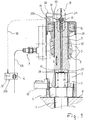
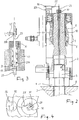
- the screw-in depth of the threaded bolt is limited by the length of the threaded section A, which is available as a bolt protrusion above the nut 4.
- the screw-in depth provided should be at least equal to the thread diameter of the bolt, preferably 1.5 times. Only the minimum screw-in depth ensures that the threaded bolt 3 is not damaged by the clamping process. If a minimum value for the length A1 of the thread engagement is not observed, the end of the threaded bolt can tear off.
- a gear 15 working through openings in the support tube 2 can be provided with which the nut 4 screwed onto the threaded bolt 3 can be rotated. This turning is of course only possible when the clamping device is working and therefore the nut 4 is not subjected to considerable friction.
- the interchangeable socket 10 is composed in one piece from a lower coupling section and an upper shaft section.
- the coupling section is located inside the support tube 2 and has an internal thread which can be screwed to the external thread of the threaded bolt 3.
- the shaft section of the interchangeable socket 10 is surrounded by the piston 5 to which it is rigidly connected, preferably by a screw connection.
- a pin 20 is located centrally in a longitudinal bore of the interchangeable socket 10. This is provided with a collar or an extension 21 against which a spring 21A supported on the other hand relative to the interchangeable socket 10 is supported. In this way, the longitudinally movable pin 20 in a longitudinal guide 17 of the interchangeable socket is always acted upon by a force which pushes it slightly downwards, ie. H. towards the threaded bolt 3, is applied.
Landscapes
- Engineering & Computer Science (AREA)
- Mechanical Engineering (AREA)
- General Engineering & Computer Science (AREA)
- Hand Tools For Fitting Together And Separating, Or Other Hand Tools (AREA)
- Clamps And Clips (AREA)
- Force Measurement Appropriate To Specific Purposes (AREA)
Claims (9)
- Dispositif de serrage pour l'étirement d'un boulon fileté par traction sur sa section d'extrémité de filetage (A), comprenant un tube de support (2) entourant la section d'extrémité de filetage (A), un cylindre (1) agencé dans le prolongement du tube de support (2), comprenant au moins un piston (5) mobile dans celui-ci dans la direction longitudinale (L), raccordable avec une alimentation hydraulique (6), une douille de remplacement (10) pouvant être vissée avec la section d'extrémité de filetage (A), configurée sous forme entraînable axialement par le piston (5), et une tige (20) agencée sous forme mobile dans la direction longitudinale (L), dont l'extrémité de tige (22) peut être supportée dans la direction longitudinale contre l'extrémité, comprenant la section d'extrémité de filetage (A), du boulon fileté, caractérisé par- des moyens (30) pour déterminer la position de la tige (20) dans la direction longitudinale (L) par rapport à la douille de remplacement (10),- une unité d'évaluation et de commande (35A, 35B) raccordée avec les moyens de détermination (30), par laquelle l'alimentation hydraulique (6) peut être libérée, dans la mesure où la position longitudinale de la tige correspond à une valeur de position minimale prédéterminée en interne, et une longueur de prise de filetage effective suffisante est par conséquent présente entre la douille de remplacement (10) et l'extrémité du boulon fileté.
- Dispositif de serrage selon la revendication 1, caractérisé en ce qu'un constituant de l'unité d'évaluation et de commande (35A, 35B) est une voie de signalisation sans fil comprenant un module d'envoi (36) agencé sur le cylindre (1) et un module de réception (37) agencé dans la zone de l'alimentation hydraulique (6).
- Dispositif de serrage selon la revendication 1 ou 2, caractérisé par des moyens (30) fonctionnant par induction pour la détermination de la position de la tige (20).
- Dispositif de serrage selon l'une quelconque des revendications précédentes, caractérisé en ce que les moyens de détermination (30) sont agencés dans la zone de l'autre extrémité de tige (23).
- Dispositif de serrage selon l'une quelconque des revendications précédentes, caractérisé par une unité de visualisation (50) agencée sur le cylindre (1) pour la position de la tige (20) dans la direction longitudinale (L).
- Dispositif de serrage selon la revendication 5, caractérisé en ce que la tige (20) comprend une section émettant un signal ou déclenchant un signal (23), au niveau de laquelle la tige (20) modifie son diamètre.
- Dispositif de serrage selon l'une quelconque des revendications précédentes, caractérisé en ce que la tige (20) est agencée dans un guide longitudinal (17) dans la douille de remplacement (10).
- Dispositif de serrage selon l'une quelconque des revendications précédentes, caractérisé en ce que la tige (20) est configurée sous forme élargie radialement (25) au niveau de son extrémité de tige inférieure (22) en comparaison de la section transversale de tige.
- Dispositif de serrage selon l'une quelconque des revendications précédentes, caractérisé en ce que l'élargissement (25), à l'opposé de la surface frontale du boulon fileté, est pourvu d'un élément d'identification fonctionnant à la manière d'un capteur, détectant au moins une caractéristique réalisée sur la surface frontale.
Priority Applications (1)
| Application Number | Priority Date | Filing Date | Title |
|---|---|---|---|
| PL13176053T PL2687320T3 (pl) | 2012-07-18 | 2013-07-11 | Urządzenie naciągające do wydłużania sworznia gwintowanego |
Applications Claiming Priority (1)
| Application Number | Priority Date | Filing Date | Title |
|---|---|---|---|
| DE102012106503.9A DE102012106503B4 (de) | 2012-07-18 | 2012-07-18 | Spannvorrichtung zum Dehnen eines Gewindebolzens |
Publications (3)
| Publication Number | Publication Date |
|---|---|
| EP2687320A2 EP2687320A2 (fr) | 2014-01-22 |
| EP2687320A3 EP2687320A3 (fr) | 2018-01-03 |
| EP2687320B1 true EP2687320B1 (fr) | 2020-09-02 |
Family
ID=48748066
Family Applications (1)
| Application Number | Title | Priority Date | Filing Date |
|---|---|---|---|
| EP13176053.0A Active EP2687320B1 (fr) | 2012-07-18 | 2013-07-11 | Dispositif de serrage pour l'étirement d'un boulon fileté |
Country Status (6)
| Country | Link |
|---|---|
| US (2) | US20140020515A1 (fr) |
| EP (1) | EP2687320B1 (fr) |
| JP (1) | JP6249655B2 (fr) |
| DE (1) | DE102012106503B4 (fr) |
| ES (1) | ES2827001T3 (fr) |
| PL (1) | PL2687320T3 (fr) |
Families Citing this family (20)
| Publication number | Priority date | Publication date | Assignee | Title |
|---|---|---|---|---|
| US20130008015A1 (en) * | 2010-02-08 | 2013-01-10 | Junkers John K | Apparatus and methods for tightening threaded fasteners |
| CN106102991B (zh) * | 2014-02-06 | 2020-04-24 | 坦泰克有限公司 | 张紧器 |
| US10041594B2 (en) | 2014-12-15 | 2018-08-07 | Forum Us, Inc. | Energized screw gland |
| US9995300B2 (en) | 2015-12-02 | 2018-06-12 | Forum Us, Inc. | Cartridge retention system |
| DE102016205086A1 (de) * | 2016-03-29 | 2017-10-05 | Aktiebolaget Skf | Stangenspannvorrichtung und Montageverfahren für eine solche Vorrichtung auf einer Stange |
| US10252405B2 (en) * | 2016-05-19 | 2019-04-09 | Forum Us, Inc. | Bolt tensioning system |
| US10800020B2 (en) * | 2016-05-19 | 2020-10-13 | Enerpac Tool Group Corp. | Tensioning device and method for tensioning a workpiece |
| DE102016113196A1 (de) * | 2016-07-18 | 2018-01-18 | Frank Hohmann | Digitale Gewindeeingriffsmessung |
| DE102017119676A1 (de) * | 2017-08-28 | 2019-02-28 | Frank Hohmann | Verfahren zum dokumentierten Anziehen oder Nachziehen einer Schraubverbindung |
| DE102018107657A1 (de) * | 2018-03-29 | 2019-10-02 | Frank Hohmann | Vorrichtung zum Anziehen von Schraubverbindungen |
| DE102018117256A1 (de) * | 2018-07-17 | 2020-01-23 | Frank Hohmann | Verfahren zum dokumentierten Anziehen oder Nachziehen einer Schraubverbindung |
| CN109341928B (zh) * | 2018-12-12 | 2023-09-05 | 江苏徐工工程机械研究院有限公司 | 螺栓预紧力测量装置及方法 |
| GB2580102B (en) * | 2018-12-21 | 2021-08-25 | Caterpillar Energy Solutions Gmbh | System for tensioning at least one connecting element |
| DE102019102133A1 (de) * | 2019-01-29 | 2020-07-30 | Frank Hohmann | Verfahren zum dokumentierten Anziehen oder Nachziehen einer Schraubverbindung |
| US11602810B2 (en) * | 2019-01-29 | 2023-03-14 | Jörg Hohmann | Method for documented tightening and re-tightening of a screw connection |
| WO2020182442A1 (fr) * | 2019-03-11 | 2020-09-17 | Atlas Copco Industrial Technique Ab | Outil de tension de boulon |
| EP4126459A1 (fr) | 2020-03-25 | 2023-02-08 | Milwaukee Electric Tool Corporation | Outil de serrage de boulon |
| CN111408931B (zh) * | 2020-04-10 | 2021-09-21 | 江苏明璐不锈钢有限公司 | 一种液压螺栓拉伸器 |
| UA145046U (uk) * | 2020-09-04 | 2020-11-10 | Товариство З Обмеженою Відповідальністю "Svs Ltd" | Пристрій для створення зусилля при герметизації фланцевих з'єднань головних роз'ємів корпусів насосів |
| CN115383454A (zh) * | 2022-10-14 | 2022-11-25 | 大连德新机电技术工程有限公司 | 双头螺柱拧紧装置及控制方法 |
Family Cites Families (18)
| Publication number | Priority date | Publication date | Assignee | Title |
|---|---|---|---|---|
| US3679173A (en) * | 1970-08-06 | 1972-07-25 | Diamond Power Speciality | Self-aligning tensioner |
| DE2749536C3 (de) * | 1977-11-03 | 1980-09-04 | Kraftwerk Union Ag, 4330 Muelheim | Anordnung zum Messen der Vorspannung eines insbesondere zum Verschluß eines Reaktordruckbehälters dienenden Schraubenbolzens |
| JPS6047072B2 (ja) * | 1981-12-25 | 1985-10-19 | 株式会社日本製鋼所 | スタツドテンシヨニング装置の群制御装置 |
| JPS63120142U (fr) * | 1987-01-28 | 1988-08-03 | ||
| US5257207A (en) | 1989-07-14 | 1993-10-26 | Warren Richard P | Method for monitoring gasket compression during fastener tensioning |
| JPH03204406A (ja) * | 1990-01-08 | 1991-09-06 | Hitachi Ltd | ボルト引張装置及び方法 |
| US5249208A (en) * | 1990-11-09 | 1993-09-28 | Frank Ruzga | Automatic pressure vessel servicing apparatus |
| DE4313778A1 (de) * | 1993-04-27 | 1994-11-03 | Westfalia Becorit Ind Tech | Schraubenspannvorrichtung |
| DE9316464U1 (de) * | 1993-10-28 | 1994-01-20 | Wagner, Paul-Heinz, 53804 Much | Spannvorrichtung zum Dehnen von Schrauben |
| US8033181B2 (en) * | 2001-01-29 | 2011-10-11 | Innovation Plus, Llc | Probe for fastener identification and ultrasonic load measurement |
| JP2002239939A (ja) * | 2001-02-19 | 2002-08-28 | Hitachi Engineering & Services Co Ltd | ボルトの締付けトルク管理装置 |
| DE102004043145B3 (de) * | 2004-09-03 | 2006-05-18 | Hohmann, Jörg | Hydraulische Schraubenspannvorrichtung |
| DE102004043146B3 (de) * | 2004-09-03 | 2005-11-24 | Hohmann, Jörg | Hydraulische Schraubenspannvorrichtung |
| DE102005015922B4 (de) | 2005-04-06 | 2007-08-02 | Hohmann, Jörg | Hydraulische Gewindebolzenspannvorrichtung und Verfahren zum Anziehen von großen Schrauben mittels der hydraulischen Gewindebolzenspannvorrichtung |
| DE102005044917A1 (de) * | 2005-09-20 | 2007-04-19 | As Tech Industrie- Und Spannhydraulik Gmbh | Anordnung zur Erfassung von Messgrößen in Schraubverbindungen |
| US7703669B2 (en) * | 2007-10-31 | 2010-04-27 | The Boeing Company | Intelligent fastener installation system |
| US20110271798A1 (en) * | 2008-11-14 | 2011-11-10 | Wagner Vermogensverwaltungs- GMBH & Co.KG | Screw tensioning device |
| US9193051B2 (en) | 2010-04-02 | 2015-11-24 | Aktiebolaget Skf | Multiple stud tensioning machine and method for automatically controlling the elongation of a plurality of studs |
-
2012
- 2012-07-18 DE DE102012106503.9A patent/DE102012106503B4/de active Active
-
2013
- 2013-07-11 EP EP13176053.0A patent/EP2687320B1/fr active Active
- 2013-07-11 ES ES13176053T patent/ES2827001T3/es active Active
- 2013-07-11 PL PL13176053T patent/PL2687320T3/pl unknown
- 2013-07-15 US US13/941,581 patent/US20140020515A1/en not_active Abandoned
- 2013-07-18 JP JP2013149424A patent/JP6249655B2/ja active Active
-
2016
- 2016-12-19 US US15/383,471 patent/US20170095896A1/en not_active Abandoned
Non-Patent Citations (1)
| Title |
|---|
| None * |
Also Published As
| Publication number | Publication date |
|---|---|
| EP2687320A3 (fr) | 2018-01-03 |
| PL2687320T3 (pl) | 2021-02-08 |
| JP6249655B2 (ja) | 2017-12-20 |
| DE102012106503B4 (de) | 2023-03-16 |
| DE102012106503A1 (de) | 2014-01-23 |
| ES2827001T3 (es) | 2021-05-19 |
| EP2687320A2 (fr) | 2014-01-22 |
| US20140020515A1 (en) | 2014-01-23 |
| JP2014018960A (ja) | 2014-02-03 |
| US20170095896A1 (en) | 2017-04-06 |
Similar Documents
| Publication | Publication Date | Title |
|---|---|---|
| EP2687320B1 (fr) | Dispositif de serrage pour l'étirement d'un boulon fileté | |
| EP2679336B1 (fr) | Dispositif de serrage pour l'étirement d'un boulon fileté | |
| EP3597369B1 (fr) | Procédé de vissage ou de dévissage attesté d'un raccord à vis | |
| EP3453489B1 (fr) | Procédé de vissage ou de dévissage attesté d'un raccord à vis | |
| EP2346643B1 (fr) | Dispositif de serrage pour vis | |
| EP2708327B1 (fr) | Dispositif de serrage pour l'expansion d'un boulon fileté et outil approprié, de préférence adaptateur d'entraînement | |
| EP3272462B1 (fr) | Dispositif de serrage pour l'etirement d'un boulon filete | |
| EP2052808A1 (fr) | Dispositif de serrage doté d'un mandrin destiné à la fixation amovible d'un support de pièces à usiner | |
| EP3698924B1 (fr) | Procédé de vissage ou de dévissage attesté d'un raccord à vis | |
| EP3554707B1 (fr) | Fixation et séparation d'un ensemble piston-cylindre sur/d'un dispositif servant à aspirer et à expulser des volumes de fluide | |
| EP3049214B1 (fr) | Machine-outil munie d'un dispositif de mesure de dureté | |
| DE102009014230A1 (de) | System zum gleichzeitigen Anziehen von mehreren Verschraubungen in einem Arbeitsgang | |
| DE102013006831B4 (de) | Spannsystem zum Spannen eines Stempels an einem Stößel einer Fließdruckpresse | |
| EP3404197B1 (fr) | Dispositif de forage et procédé de vissage d'éléments de tiges de forage comprenant un dispositif de forage | |
| DE102019102133A1 (de) | Verfahren zum dokumentierten Anziehen oder Nachziehen einer Schraubverbindung | |
| DE102017114018B4 (de) | Radservicemaschine mit Krafterfassungseinrichtung | |
| DE69708091T2 (de) | Sicherheitsvorrichtung für vorgespante muttern | |
| AT518874B1 (de) | Bearbeitungsmaschine | |
| DE2229073A1 (de) | Hydraulische spannvorrichtung | |
| DE102009037212A1 (de) | Kronenbohrer | |
| DE102009037483A1 (de) | Kronenbohrer | |
| CH691527A5 (de) | Presswerkzeug mit elektronischer Sicherheitseinheit | |
| DE2423862A1 (de) | Vorrichtung zum befestigen eines koerpers an einem haltekoerper, insbesondere eines werkzeugteiles an einer presse | |
| EP2123404A1 (fr) | Dispositif de pressage portatif | |
| WO2010049831A2 (fr) | Aléseur fileté et porte-outil |
Legal Events
| Date | Code | Title | Description |
|---|---|---|---|
| PUAI | Public reference made under article 153(3) epc to a published international application that has entered the european phase |
Free format text: ORIGINAL CODE: 0009012 |
|
| AK | Designated contracting states |
Kind code of ref document: A2 Designated state(s): AL AT BE BG CH CY CZ DE DK EE ES FI FR GB GR HR HU IE IS IT LI LT LU LV MC MK MT NL NO PL PT RO RS SE SI SK SM TR |
|
| AX | Request for extension of the european patent |
Extension state: BA ME |
|
| PUAL | Search report despatched |
Free format text: ORIGINAL CODE: 0009013 |
|
| AK | Designated contracting states |
Kind code of ref document: A3 Designated state(s): AL AT BE BG CH CY CZ DE DK EE ES FI FR GB GR HR HU IE IS IT LI LT LU LV MC MK MT NL NO PL PT RO RS SE SI SK SM TR |
|
| AX | Request for extension of the european patent |
Extension state: BA ME |
|
| RIC1 | Information provided on ipc code assigned before grant |
Ipc: G01L 5/24 20060101ALN20171130BHEP Ipc: F16B 31/04 20060101ALN20171130BHEP Ipc: B25B 29/02 20060101ALI20171130BHEP Ipc: B23P 19/06 20060101AFI20171130BHEP Ipc: F16B 31/02 20060101ALN20171130BHEP |
|
| STAA | Information on the status of an ep patent application or granted ep patent |
Free format text: STATUS: REQUEST FOR EXAMINATION WAS MADE |
|
| 17P | Request for examination filed |
Effective date: 20180417 |
|
| RBV | Designated contracting states (corrected) |
Designated state(s): AL AT BE BG CH CY CZ DE DK EE ES FI FR GB GR HR HU IE IS IT LI LT LU LV MC MK MT NL NO PL PT RO RS SE SI SK SM TR |
|
| STAA | Information on the status of an ep patent application or granted ep patent |
Free format text: STATUS: EXAMINATION IS IN PROGRESS |
|
| 17Q | First examination report despatched |
Effective date: 20190405 |
|
| REG | Reference to a national code |
Ref country code: DE Ref legal event code: R079 Ref document number: 502013015076 Country of ref document: DE Free format text: PREVIOUS MAIN CLASS: B23P0019060000 Ipc: B25B0029020000 |
|
| GRAP | Despatch of communication of intention to grant a patent |
Free format text: ORIGINAL CODE: EPIDOSNIGR1 |
|
| STAA | Information on the status of an ep patent application or granted ep patent |
Free format text: STATUS: GRANT OF PATENT IS INTENDED |
|
| RIC1 | Information provided on ipc code assigned before grant |
Ipc: B25B 29/02 20060101AFI20200319BHEP Ipc: B23P 19/06 20060101ALI20200319BHEP Ipc: F16B 31/04 20060101ALI20200319BHEP Ipc: F16B 31/02 20060101ALI20200319BHEP |
|
| INTG | Intention to grant announced |
Effective date: 20200403 |
|
| GRAS | Grant fee paid |
Free format text: ORIGINAL CODE: EPIDOSNIGR3 |
|
| GRAA | (expected) grant |
Free format text: ORIGINAL CODE: 0009210 |
|
| STAA | Information on the status of an ep patent application or granted ep patent |
Free format text: STATUS: THE PATENT HAS BEEN GRANTED |
|
| AK | Designated contracting states |
Kind code of ref document: B1 Designated state(s): AL AT BE BG CH CY CZ DE DK EE ES FI FR GB GR HR HU IE IS IT LI LT LU LV MC MK MT NL NO PL PT RO RS SE SI SK SM TR |
|
| REG | Reference to a national code |
Ref country code: GB Ref legal event code: FG4D Free format text: NOT ENGLISH |
|
| REG | Reference to a national code |
Ref country code: AT Ref legal event code: REF Ref document number: 1308288 Country of ref document: AT Kind code of ref document: T Effective date: 20200915 Ref country code: CH Ref legal event code: EP |
|
| REG | Reference to a national code |
Ref country code: DE Ref legal event code: R096 Ref document number: 502013015076 Country of ref document: DE |
|
| REG | Reference to a national code |
Ref country code: IE Ref legal event code: FG4D Free format text: LANGUAGE OF EP DOCUMENT: GERMAN |
|
| REG | Reference to a national code |
Ref country code: SE Ref legal event code: TRGR |
|
| REG | Reference to a national code |
Ref country code: LT Ref legal event code: MG4D |
|
| PG25 | Lapsed in a contracting state [announced via postgrant information from national office to epo] |
Ref country code: FI Free format text: LAPSE BECAUSE OF FAILURE TO SUBMIT A TRANSLATION OF THE DESCRIPTION OR TO PAY THE FEE WITHIN THE PRESCRIBED TIME-LIMIT Effective date: 20200902 Ref country code: LT Free format text: LAPSE BECAUSE OF FAILURE TO SUBMIT A TRANSLATION OF THE DESCRIPTION OR TO PAY THE FEE WITHIN THE PRESCRIBED TIME-LIMIT Effective date: 20200902 Ref country code: HR Free format text: LAPSE BECAUSE OF FAILURE TO SUBMIT A TRANSLATION OF THE DESCRIPTION OR TO PAY THE FEE WITHIN THE PRESCRIBED TIME-LIMIT Effective date: 20200902 Ref country code: GR Free format text: LAPSE BECAUSE OF FAILURE TO SUBMIT A TRANSLATION OF THE DESCRIPTION OR TO PAY THE FEE WITHIN THE PRESCRIBED TIME-LIMIT Effective date: 20201203 Ref country code: NO Free format text: LAPSE BECAUSE OF FAILURE TO SUBMIT A TRANSLATION OF THE DESCRIPTION OR TO PAY THE FEE WITHIN THE PRESCRIBED TIME-LIMIT Effective date: 20201202 Ref country code: BG Free format text: LAPSE BECAUSE OF FAILURE TO SUBMIT A TRANSLATION OF THE DESCRIPTION OR TO PAY THE FEE WITHIN THE PRESCRIBED TIME-LIMIT Effective date: 20201202 |
|
| REG | Reference to a national code |
Ref country code: NL Ref legal event code: MP Effective date: 20200902 |
|
| PG25 | Lapsed in a contracting state [announced via postgrant information from national office to epo] |
Ref country code: RS Free format text: LAPSE BECAUSE OF FAILURE TO SUBMIT A TRANSLATION OF THE DESCRIPTION OR TO PAY THE FEE WITHIN THE PRESCRIBED TIME-LIMIT Effective date: 20200902 Ref country code: LV Free format text: LAPSE BECAUSE OF FAILURE TO SUBMIT A TRANSLATION OF THE DESCRIPTION OR TO PAY THE FEE WITHIN THE PRESCRIBED TIME-LIMIT Effective date: 20200902 |
|
| PG25 | Lapsed in a contracting state [announced via postgrant information from national office to epo] |
Ref country code: EE Free format text: LAPSE BECAUSE OF FAILURE TO SUBMIT A TRANSLATION OF THE DESCRIPTION OR TO PAY THE FEE WITHIN THE PRESCRIBED TIME-LIMIT Effective date: 20200902 Ref country code: CZ Free format text: LAPSE BECAUSE OF FAILURE TO SUBMIT A TRANSLATION OF THE DESCRIPTION OR TO PAY THE FEE WITHIN THE PRESCRIBED TIME-LIMIT Effective date: 20200902 Ref country code: PT Free format text: LAPSE BECAUSE OF FAILURE TO SUBMIT A TRANSLATION OF THE DESCRIPTION OR TO PAY THE FEE WITHIN THE PRESCRIBED TIME-LIMIT Effective date: 20210104 Ref country code: NL Free format text: LAPSE BECAUSE OF FAILURE TO SUBMIT A TRANSLATION OF THE DESCRIPTION OR TO PAY THE FEE WITHIN THE PRESCRIBED TIME-LIMIT Effective date: 20200902 Ref country code: SM Free format text: LAPSE BECAUSE OF FAILURE TO SUBMIT A TRANSLATION OF THE DESCRIPTION OR TO PAY THE FEE WITHIN THE PRESCRIBED TIME-LIMIT Effective date: 20200902 Ref country code: RO Free format text: LAPSE BECAUSE OF FAILURE TO SUBMIT A TRANSLATION OF THE DESCRIPTION OR TO PAY THE FEE WITHIN THE PRESCRIBED TIME-LIMIT Effective date: 20200902 |
|
| REG | Reference to a national code |
Ref country code: ES Ref legal event code: FG2A Ref document number: 2827001 Country of ref document: ES Kind code of ref document: T3 Effective date: 20210519 |
|
| PG25 | Lapsed in a contracting state [announced via postgrant information from national office to epo] |
Ref country code: AL Free format text: LAPSE BECAUSE OF FAILURE TO SUBMIT A TRANSLATION OF THE DESCRIPTION OR TO PAY THE FEE WITHIN THE PRESCRIBED TIME-LIMIT Effective date: 20200902 Ref country code: IS Free format text: LAPSE BECAUSE OF FAILURE TO SUBMIT A TRANSLATION OF THE DESCRIPTION OR TO PAY THE FEE WITHIN THE PRESCRIBED TIME-LIMIT Effective date: 20210102 |
|
| REG | Reference to a national code |
Ref country code: DE Ref legal event code: R097 Ref document number: 502013015076 Country of ref document: DE |
|
| PG25 | Lapsed in a contracting state [announced via postgrant information from national office to epo] |
Ref country code: SK Free format text: LAPSE BECAUSE OF FAILURE TO SUBMIT A TRANSLATION OF THE DESCRIPTION OR TO PAY THE FEE WITHIN THE PRESCRIBED TIME-LIMIT Effective date: 20200902 |
|
| PLBE | No opposition filed within time limit |
Free format text: ORIGINAL CODE: 0009261 |
|
| STAA | Information on the status of an ep patent application or granted ep patent |
Free format text: STATUS: NO OPPOSITION FILED WITHIN TIME LIMIT |
|
| 26N | No opposition filed |
Effective date: 20210603 |
|
| PG25 | Lapsed in a contracting state [announced via postgrant information from national office to epo] |
Ref country code: SI Free format text: LAPSE BECAUSE OF FAILURE TO SUBMIT A TRANSLATION OF THE DESCRIPTION OR TO PAY THE FEE WITHIN THE PRESCRIBED TIME-LIMIT Effective date: 20200902 Ref country code: DK Free format text: LAPSE BECAUSE OF FAILURE TO SUBMIT A TRANSLATION OF THE DESCRIPTION OR TO PAY THE FEE WITHIN THE PRESCRIBED TIME-LIMIT Effective date: 20200902 |
|
| PG25 | Lapsed in a contracting state [announced via postgrant information from national office to epo] |
Ref country code: IT Free format text: LAPSE BECAUSE OF FAILURE TO SUBMIT A TRANSLATION OF THE DESCRIPTION OR TO PAY THE FEE WITHIN THE PRESCRIBED TIME-LIMIT Effective date: 20200902 |
|
| REG | Reference to a national code |
Ref country code: DE Ref legal event code: R082 Ref document number: 502013015076 Country of ref document: DE Representative=s name: JANKE SCHOLL PATENTANWAELTE PARTG MBB, DE |
|
| PG25 | Lapsed in a contracting state [announced via postgrant information from national office to epo] |
Ref country code: MC Free format text: LAPSE BECAUSE OF FAILURE TO SUBMIT A TRANSLATION OF THE DESCRIPTION OR TO PAY THE FEE WITHIN THE PRESCRIBED TIME-LIMIT Effective date: 20200902 |
|
| REG | Reference to a national code |
Ref country code: BE Ref legal event code: MM Effective date: 20210731 |
|
| PG25 | Lapsed in a contracting state [announced via postgrant information from national office to epo] |
Ref country code: LU Free format text: LAPSE BECAUSE OF NON-PAYMENT OF DUE FEES Effective date: 20210711 Ref country code: FR Free format text: LAPSE BECAUSE OF NON-PAYMENT OF DUE FEES Effective date: 20210731 |
|
| PG25 | Lapsed in a contracting state [announced via postgrant information from national office to epo] |
Ref country code: IE Free format text: LAPSE BECAUSE OF NON-PAYMENT OF DUE FEES Effective date: 20210711 Ref country code: BE Free format text: LAPSE BECAUSE OF NON-PAYMENT OF DUE FEES Effective date: 20210731 |
|
| REG | Reference to a national code |
Ref country code: AT Ref legal event code: MM01 Ref document number: 1308288 Country of ref document: AT Kind code of ref document: T Effective date: 20210711 |
|
| PG25 | Lapsed in a contracting state [announced via postgrant information from national office to epo] |
Ref country code: AT Free format text: LAPSE BECAUSE OF NON-PAYMENT OF DUE FEES Effective date: 20210711 |
|
| PG25 | Lapsed in a contracting state [announced via postgrant information from national office to epo] |
Ref country code: HU Free format text: LAPSE BECAUSE OF FAILURE TO SUBMIT A TRANSLATION OF THE DESCRIPTION OR TO PAY THE FEE WITHIN THE PRESCRIBED TIME-LIMIT; INVALID AB INITIO Effective date: 20130711 |
|
| PG25 | Lapsed in a contracting state [announced via postgrant information from national office to epo] |
Ref country code: CY Free format text: LAPSE BECAUSE OF FAILURE TO SUBMIT A TRANSLATION OF THE DESCRIPTION OR TO PAY THE FEE WITHIN THE PRESCRIBED TIME-LIMIT Effective date: 20200902 |
|
| P01 | Opt-out of the competence of the unified patent court (upc) registered |
Effective date: 20230530 |
|
| PG25 | Lapsed in a contracting state [announced via postgrant information from national office to epo] |
Ref country code: MK Free format text: LAPSE BECAUSE OF FAILURE TO SUBMIT A TRANSLATION OF THE DESCRIPTION OR TO PAY THE FEE WITHIN THE PRESCRIBED TIME-LIMIT Effective date: 20200902 |
|
| PG25 | Lapsed in a contracting state [announced via postgrant information from national office to epo] |
Ref country code: MT Free format text: LAPSE BECAUSE OF FAILURE TO SUBMIT A TRANSLATION OF THE DESCRIPTION OR TO PAY THE FEE WITHIN THE PRESCRIBED TIME-LIMIT Effective date: 20200902 |
|
| PGFP | Annual fee paid to national office [announced via postgrant information from national office to epo] |
Ref country code: PL Payment date: 20250623 Year of fee payment: 13 |
|
| PGFP | Annual fee paid to national office [announced via postgrant information from national office to epo] |
Ref country code: ES Payment date: 20250826 Year of fee payment: 13 |
|
| PGFP | Annual fee paid to national office [announced via postgrant information from national office to epo] |
Ref country code: DE Payment date: 20250722 Year of fee payment: 13 |
|
| PGFP | Annual fee paid to national office [announced via postgrant information from national office to epo] |
Ref country code: GB Payment date: 20250722 Year of fee payment: 13 |
|
| PGFP | Annual fee paid to national office [announced via postgrant information from national office to epo] |
Ref country code: CH Payment date: 20250801 Year of fee payment: 13 Ref country code: SE Payment date: 20250722 Year of fee payment: 13 |
|
| PG25 | Lapsed in a contracting state [announced via postgrant information from national office to epo] |
Ref country code: TR Free format text: LAPSE BECAUSE OF FAILURE TO SUBMIT A TRANSLATION OF THE DESCRIPTION OR TO PAY THE FEE WITHIN THE PRESCRIBED TIME-LIMIT Effective date: 20200902 |