EP2687697A2 - Dispositif de mélange pour le post-traitement de gaz d'échappement - Google Patents
Dispositif de mélange pour le post-traitement de gaz d'échappement Download PDFInfo
- Publication number
- EP2687697A2 EP2687697A2 EP13002561.2A EP13002561A EP2687697A2 EP 2687697 A2 EP2687697 A2 EP 2687697A2 EP 13002561 A EP13002561 A EP 13002561A EP 2687697 A2 EP2687697 A2 EP 2687697A2
- Authority
- EP
- European Patent Office
- Prior art keywords
- exhaust gas
- inner tube
- mixing device
- housing
- mixing
- Prior art date
- Legal status (The legal status is an assumption and is not a legal conclusion. Google has not performed a legal analysis and makes no representation as to the accuracy of the status listed.)
- Granted
Links
Images


Classifications
-
- F—MECHANICAL ENGINEERING; LIGHTING; HEATING; WEAPONS; BLASTING
- F01—MACHINES OR ENGINES IN GENERAL; ENGINE PLANTS IN GENERAL; STEAM ENGINES
- F01N—GAS-FLOW SILENCERS OR EXHAUST APPARATUS FOR MACHINES OR ENGINES IN GENERAL; GAS-FLOW SILENCERS OR EXHAUST APPARATUS FOR INTERNAL-COMBUSTION ENGINES
- F01N3/00—Exhaust or silencing apparatus having means for purifying, rendering innocuous, or otherwise treating exhaust
- F01N3/08—Exhaust or silencing apparatus having means for purifying, rendering innocuous, or otherwise treating exhaust for rendering innocuous
- F01N3/10—Exhaust or silencing apparatus having means for purifying, rendering innocuous, or otherwise treating exhaust for rendering innocuous by thermal or catalytic conversion of noxious components of exhaust
- F01N3/18—Exhaust or silencing apparatus having means for purifying, rendering innocuous, or otherwise treating exhaust for rendering innocuous by thermal or catalytic conversion of noxious components of exhaust characterised by methods of operation; Control
- F01N3/20—Exhaust or silencing apparatus having means for purifying, rendering innocuous, or otherwise treating exhaust for rendering innocuous by thermal or catalytic conversion of noxious components of exhaust characterised by methods of operation; Control specially adapted for catalytic conversion
- F01N3/206—Adding periodically or continuously substances to exhaust gases for promoting purification, e.g. catalytic material in liquid form, NOx reducing agents
- F01N3/2066—Selective catalytic reduction [SCR]
-
- B—PERFORMING OPERATIONS; TRANSPORTING
- B01—PHYSICAL OR CHEMICAL PROCESSES OR APPARATUS IN GENERAL
- B01F—MIXING, e.g. DISSOLVING, EMULSIFYING OR DISPERSING
- B01F23/00—Mixing according to the phases to be mixed, e.g. dispersing or emulsifying
- B01F23/20—Mixing gases with liquids
- B01F23/21—Mixing gases with liquids by introducing liquids into gaseous media
- B01F23/213—Mixing gases with liquids by introducing liquids into gaseous media by spraying or atomising of the liquids
- B01F23/2132—Mixing gases with liquids by introducing liquids into gaseous media by spraying or atomising of the liquids using nozzles
-
- B—PERFORMING OPERATIONS; TRANSPORTING
- B01—PHYSICAL OR CHEMICAL PROCESSES OR APPARATUS IN GENERAL
- B01F—MIXING, e.g. DISSOLVING, EMULSIFYING OR DISPERSING
- B01F25/00—Flow mixers; Mixers for falling materials, e.g. solid particles
- B01F25/10—Mixing by creating a vortex flow, e.g. by tangential introduction of flow components
- B01F25/102—Mixing by creating a vortex flow, e.g. by tangential introduction of flow components wherein the vortex is created by two or more jets introduced tangentially in separate mixing chambers or consecutively in the same mixing chamber
-
- B—PERFORMING OPERATIONS; TRANSPORTING
- B01—PHYSICAL OR CHEMICAL PROCESSES OR APPARATUS IN GENERAL
- B01F—MIXING, e.g. DISSOLVING, EMULSIFYING OR DISPERSING
- B01F25/00—Flow mixers; Mixers for falling materials, e.g. solid particles
- B01F25/30—Injector mixers
- B01F25/31—Injector mixers in conduits or tubes through which the main component flows
- B01F25/313—Injector mixers in conduits or tubes through which the main component flows wherein additional components are introduced in the centre of the conduit
- B01F25/3131—Injector mixers in conduits or tubes through which the main component flows wherein additional components are introduced in the centre of the conduit with additional mixing means other than injector mixers, e.g. screens, baffles or rotating elements
-
- F—MECHANICAL ENGINEERING; LIGHTING; HEATING; WEAPONS; BLASTING
- F01—MACHINES OR ENGINES IN GENERAL; ENGINE PLANTS IN GENERAL; STEAM ENGINES
- F01N—GAS-FLOW SILENCERS OR EXHAUST APPARATUS FOR MACHINES OR ENGINES IN GENERAL; GAS-FLOW SILENCERS OR EXHAUST APPARATUS FOR INTERNAL-COMBUSTION ENGINES
- F01N3/00—Exhaust or silencing apparatus having means for purifying, rendering innocuous, or otherwise treating exhaust
- F01N3/02—Exhaust or silencing apparatus having means for purifying, rendering innocuous, or otherwise treating exhaust for cooling, or for removing solid constituents of, exhaust
- F01N3/021—Exhaust or silencing apparatus having means for purifying, rendering innocuous, or otherwise treating exhaust for cooling, or for removing solid constituents of, exhaust by means of filters
- F01N3/023—Exhaust or silencing apparatus having means for purifying, rendering innocuous, or otherwise treating exhaust for cooling, or for removing solid constituents of, exhaust by means of filters using means for regenerating the filters, e.g. by burning trapped particles
- F01N3/025—Exhaust or silencing apparatus having means for purifying, rendering innocuous, or otherwise treating exhaust for cooling, or for removing solid constituents of, exhaust by means of filters using means for regenerating the filters, e.g. by burning trapped particles using fuel burner or by adding fuel to exhaust
- F01N3/0253—Exhaust or silencing apparatus having means for purifying, rendering innocuous, or otherwise treating exhaust for cooling, or for removing solid constituents of, exhaust by means of filters using means for regenerating the filters, e.g. by burning trapped particles using fuel burner or by adding fuel to exhaust adding fuel to exhaust gases
-
- F—MECHANICAL ENGINEERING; LIGHTING; HEATING; WEAPONS; BLASTING
- F01—MACHINES OR ENGINES IN GENERAL; ENGINE PLANTS IN GENERAL; STEAM ENGINES
- F01N—GAS-FLOW SILENCERS OR EXHAUST APPARATUS FOR MACHINES OR ENGINES IN GENERAL; GAS-FLOW SILENCERS OR EXHAUST APPARATUS FOR INTERNAL-COMBUSTION ENGINES
- F01N3/00—Exhaust or silencing apparatus having means for purifying, rendering innocuous, or otherwise treating exhaust
- F01N3/08—Exhaust or silencing apparatus having means for purifying, rendering innocuous, or otherwise treating exhaust for rendering innocuous
- F01N3/10—Exhaust or silencing apparatus having means for purifying, rendering innocuous, or otherwise treating exhaust for rendering innocuous by thermal or catalytic conversion of noxious components of exhaust
- F01N3/24—Exhaust or silencing apparatus having means for purifying, rendering innocuous, or otherwise treating exhaust for rendering innocuous by thermal or catalytic conversion of noxious components of exhaust characterised by constructional aspects of converting apparatus
- F01N3/28—Construction of catalytic reactors
- F01N3/2892—Exhaust flow directors or the like, e.g. upstream of catalytic device
-
- F—MECHANICAL ENGINEERING; LIGHTING; HEATING; WEAPONS; BLASTING
- F01—MACHINES OR ENGINES IN GENERAL; ENGINE PLANTS IN GENERAL; STEAM ENGINES
- F01N—GAS-FLOW SILENCERS OR EXHAUST APPARATUS FOR MACHINES OR ENGINES IN GENERAL; GAS-FLOW SILENCERS OR EXHAUST APPARATUS FOR INTERNAL-COMBUSTION ENGINES
- F01N3/00—Exhaust or silencing apparatus having means for purifying, rendering innocuous, or otherwise treating exhaust
- F01N3/08—Exhaust or silencing apparatus having means for purifying, rendering innocuous, or otherwise treating exhaust for rendering innocuous
- F01N3/10—Exhaust or silencing apparatus having means for purifying, rendering innocuous, or otherwise treating exhaust for rendering innocuous by thermal or catalytic conversion of noxious components of exhaust
- F01N3/24—Exhaust or silencing apparatus having means for purifying, rendering innocuous, or otherwise treating exhaust for rendering innocuous by thermal or catalytic conversion of noxious components of exhaust characterised by constructional aspects of converting apparatus
- F01N3/36—Arrangements for supply of additional fuel
-
- B—PERFORMING OPERATIONS; TRANSPORTING
- B01—PHYSICAL OR CHEMICAL PROCESSES OR APPARATUS IN GENERAL
- B01F—MIXING, e.g. DISSOLVING, EMULSIFYING OR DISPERSING
- B01F25/00—Flow mixers; Mixers for falling materials, e.g. solid particles
- B01F2025/93—Arrangements, nature or configuration of flow guiding elements
- B01F2025/931—Flow guiding elements surrounding feed openings, e.g. jet nozzles
-
- F—MECHANICAL ENGINEERING; LIGHTING; HEATING; WEAPONS; BLASTING
- F01—MACHINES OR ENGINES IN GENERAL; ENGINE PLANTS IN GENERAL; STEAM ENGINES
- F01N—GAS-FLOW SILENCERS OR EXHAUST APPARATUS FOR MACHINES OR ENGINES IN GENERAL; GAS-FLOW SILENCERS OR EXHAUST APPARATUS FOR INTERNAL-COMBUSTION ENGINES
- F01N2240/00—Combination or association of two or more different exhaust treating devices, or of at least one such device with an auxiliary device, not covered by indexing codes F01N2230/00 or F01N2250/00, one of the devices being
- F01N2240/20—Combination or association of two or more different exhaust treating devices, or of at least one such device with an auxiliary device, not covered by indexing codes F01N2230/00 or F01N2250/00, one of the devices being a flow director or deflector
-
- F—MECHANICAL ENGINEERING; LIGHTING; HEATING; WEAPONS; BLASTING
- F01—MACHINES OR ENGINES IN GENERAL; ENGINE PLANTS IN GENERAL; STEAM ENGINES
- F01N—GAS-FLOW SILENCERS OR EXHAUST APPARATUS FOR MACHINES OR ENGINES IN GENERAL; GAS-FLOW SILENCERS OR EXHAUST APPARATUS FOR INTERNAL-COMBUSTION ENGINES
- F01N2610/00—Adding substances to exhaust gases
- F01N2610/02—Adding substances to exhaust gases the substance being ammonia or urea
-
- F—MECHANICAL ENGINEERING; LIGHTING; HEATING; WEAPONS; BLASTING
- F01—MACHINES OR ENGINES IN GENERAL; ENGINE PLANTS IN GENERAL; STEAM ENGINES
- F01N—GAS-FLOW SILENCERS OR EXHAUST APPARATUS FOR MACHINES OR ENGINES IN GENERAL; GAS-FLOW SILENCERS OR EXHAUST APPARATUS FOR INTERNAL-COMBUSTION ENGINES
- F01N2610/00—Adding substances to exhaust gases
- F01N2610/03—Adding substances to exhaust gases the substance being hydrocarbons, e.g. engine fuel
-
- F—MECHANICAL ENGINEERING; LIGHTING; HEATING; WEAPONS; BLASTING
- F01—MACHINES OR ENGINES IN GENERAL; ENGINE PLANTS IN GENERAL; STEAM ENGINES
- F01N—GAS-FLOW SILENCERS OR EXHAUST APPARATUS FOR MACHINES OR ENGINES IN GENERAL; GAS-FLOW SILENCERS OR EXHAUST APPARATUS FOR INTERNAL-COMBUSTION ENGINES
- F01N2610/00—Adding substances to exhaust gases
- F01N2610/06—Adding substances to exhaust gases the substance being in the gaseous form
-
- F—MECHANICAL ENGINEERING; LIGHTING; HEATING; WEAPONS; BLASTING
- F01—MACHINES OR ENGINES IN GENERAL; ENGINE PLANTS IN GENERAL; STEAM ENGINES
- F01N—GAS-FLOW SILENCERS OR EXHAUST APPARATUS FOR MACHINES OR ENGINES IN GENERAL; GAS-FLOW SILENCERS OR EXHAUST APPARATUS FOR INTERNAL-COMBUSTION ENGINES
- F01N3/00—Exhaust or silencing apparatus having means for purifying, rendering innocuous, or otherwise treating exhaust
- F01N3/08—Exhaust or silencing apparatus having means for purifying, rendering innocuous, or otherwise treating exhaust for rendering innocuous
- F01N3/10—Exhaust or silencing apparatus having means for purifying, rendering innocuous, or otherwise treating exhaust for rendering innocuous by thermal or catalytic conversion of noxious components of exhaust
- F01N3/24—Exhaust or silencing apparatus having means for purifying, rendering innocuous, or otherwise treating exhaust for rendering innocuous by thermal or catalytic conversion of noxious components of exhaust characterised by constructional aspects of converting apparatus
Definitions
- the invention relates to a mixing device for the aftertreatment of exhaust gases in an exhaust system of an internal combustion engine comprising a housing having an inlet opening having an inlet cross-section and an inner tube disposed within the housing with a mixing area formed in the interior of the inner tube, wherein at a front side of the housing a metering device for Supply of a liquid and / or a liquid-gas mixture is arranged.
- the inner tube on its lateral surface on access openings, through which the exhaust gases are introduced into the mixing area.
- the invention further relates to a method for mixing an exhaust gas with a liquid and / or a liquid-gas mixture using such a mixing device.
- a hydrolysis catalyst for reducing nitrogen oxides in an exhaust gas stream, in particular of a motor vehicle, is generally known.
- SCR selective catalytic reduction
- the exhaust gas stream is supplied with an immediately reducing substance, such as, for example, ammonia or a precursor, such as, for example, an aqueous urea solution which releases substances reducing the exhaust gas first.
- an immediately reducing substance such as, for example, ammonia or a precursor, such as, for example, an aqueous urea solution which releases substances reducing the exhaust gas first.
- the precursor is sprayed before the SCR catalyst in the exhaust stream.
- a so-called particulate filter is used regularly to minimize the emission of fines particles in a motor vehicle.
- the exhaust gas usually flows through the filter medium. This can lead to "blockage" of the particulate filter and consequently to an increase in the exhaust back pressure. This in turn has a negative effect on the engine performance and the fuel consumption of the internal combustion engine. Therefore, a particulate filter regeneration is usually carried out, which in particular by an active increase in the exhaust gas temperature of an exhaust gas stream, which then the particulate filter is supplied, is realized.
- hydrocarbons are added to the exhaust gas stream for heating the exhaust gas stream upstream of the particle filter.
- This mixture is then fed to a HC oxidation catalyst whose active component with the hydrocarbons by exothermic reaction generates a heated exhaust gas stream.
- This hot exhaust gas stream flows to the particle filter, where the carbonaceous soot particles stored in the particle filter are converted to CO, CO2, N2 and NO, whereby the particle filter is regenerated.
- the substance to be introduced into the exhaust gas which is generally liquid, is usually sprayed into the exhaust gas stream via a nozzle of a metering device.
- a uniform distribution of the liquid introduced into the exhaust gas is of essential importance.
- a mixing device of the type mentioned is, for example, in the DE 42 03 807 A1 disclosed.
- a device designed as a mixing device for the aftertreatment of exhaust gases in an exhaust system of an internal combustion engine is shown, which enables a mixing of exhaust gases with a urea solution before entering a hydrolysis catalyst.
- a conical baffle designed as an inner tube is arranged in a housing.
- the baffle has a plurality of holes as access openings in a mixing area formed within the baffle.
- a metering device designed as a pressure atomizing nozzle is arranged on the front side, via which a urea solution is supplied as a spray into the mixing region.
- the exhaust gas is introduced into the housing via an inlet opening and flows through the bores of the guide plate into the mixing area in which the exhaust gas is mixed with the spray.
- the disadvantage here, however, that act on the introduced spray in the circumferential direction through the introduced via the holes exhaust gas different strong forces, resulting in a deflection and thus to an asymmetrical spread of the spray. As a result, the spray is not homogeneously mixed with the urea.
- the invention is based on the first object to provide a mixing device which is as homogeneous as possible mixing a liquid and / or a liquid-gas mixture with the exhaust gas is guaranteed independently or only with little influence of an inflowing inflowing exhaust gas flow volume. Furthermore, the invention has the second object of providing a method for mixing a liquid and / or a liquid-gas mixture with the exhaust gas as homogeneously as possible.
- a mixing device for the aftertreatment of exhaust gases in an exhaust system of an internal combustion engine comprising a housing having an inlet opening having an inlet cross-section and an inner tube disposed within the housing with a mixing area formed in the interior of the inner tube, wherein at one end side of the housing a metering device for supplying a liquid and / or a liquid-gas mixture is arranged, and wherein the inner tube has on its lateral surface access openings through which the exhaust gases are introduced into the mixing region.
- the housing has a spiral-shaped housing section, wherein the spiral-shaped housing section extends at least along all access openings of the inner tube.
- the invention is based in a first step on the consideration that for a homogeneous mixing of the introduced in particular in the form of a spray liquid and / or the introduced liquid-gas mixture with the exhaust gas, a homogeneous spread of the spray in the mixing area is required.
- the invention is based on the consideration that for a homogeneous spreading of the spray on this circumferentially around the central main flow axis of the spray uniform flow forces must prevail. In other words, uniform flow and pressure conditions must be present in the circumferential direction. Therefore, the invention provides that the housing has a spiral-shaped housing section, which extends at least along all access openings of the inner tube.
- the spiral shape ensures that approximately equal flow and pressure conditions prevail on the outer lateral surface along the section of the inner tube provided with access openings, so that, in particular in the circumferential direction, a uniform supply of the exhaust gas over the Access openings in the mixing area and can form rotationally symmetric flow conditions in the mixing area.
- the inlet opening of the housing is used in particular for the supply of exhaust gas into the housing.
- the inner tube has as a main body in particular an elongated hollow body with a circular, oval, rectangular or polygonal cross section.
- Within the inner tube of the mixing region is formed, in which the exhaust gas is mixed with a supplied via the metering liquid and / or a liquid-gas mixture.
- the liquid contains in particular urea and / or hydrocarbon.
- the spiral-shaped housing section leads, in particular, the exhaust gas flowing in via the inlet opening towards the inner tube and in the circumferential direction along the inner tube. Due to the spiral shape occurs in this housing section in the circumferential direction a reduction in volume between the lateral surface of the inner tube and the housing wall and a spiral housing portion flowing through the exhaust stream is impressed by the spiral shape a certain twist.
- This spiral housing section extends at least along all the access openings, that is, all access openings of the inner tube are arranged within this housing section.
- the invention has the advantage that thereby a mixing device is provided, which ensures the most homogeneous possible mixing of a liquid and / or a liquid-gas mixture with the exhaust gas, or only with little influence of the inflowing exhaust gas volume flow.
- a mixing device is provided, which ensures the most homogeneous possible mixing of a liquid and / or a liquid-gas mixture with the exhaust gas, or only with little influence of the inflowing exhaust gas volume flow.
- a passage cross-section formed by the access openings advantageously decreases toward the axial end of the inner tube facing away from the metering device.
- the passage cross-section is the cross-sectional area which is available to the exhaust gas due to the inlet openings for entry into the mixing area.
- This passage cross-section can, for example, steadily decrease towards the end facing away from the metering device.
- the passage cross-section may, however, also decrease, in particular in regions, toward the end facing away from the metering device.
- the passage cross-section is greater in a region close to the dosing device than the passage cross-section in a dosing device-remote region.
- the individual areas are essentially the same size.
- a region is formed by a defined peripheral surface of the inner tube, this peripheral surface resulting from the sum of the area of the solid material and the cross-sectional area of the access openings.
- the ratio of the area of the solid material to the cross-sectional area of the access openings in a dosing device-near area is smaller than the ratio of the area of the solid material to the cross-sectional area of the access openings in a dosing device remote area.
- the number of access openings expediently decreases at least in places towards the axial end of the inner tube facing away from the metering device.
- the decrease of the passage cross section formed by the access openings to the axial end of the inner tube facing away from the metering device can be realized in a relatively simple manner. This ensures, in particular in the case of an exhaust gas flowing into the housing from the axial direction, that the exhaust gas flowing into the inner pipe runs as homogeneously as possible into the mixing area along the entire section of the inner pipe provided with access openings flows.
- the distance between two adjacent access openings in the axial direction and / or in the circumferential direction increases towards the axial end of the inner tube facing away from the metering device.
- the number of access openings can thereby steadily decrease towards the end facing away from the metering device.
- the number of access openings may also decrease in some areas towards the end facing away from the metering device. In other words, the number of access openings in a dosing device remote area is smaller than the number of access openings in a dosing device nearer area.
- the cross-sectional area of the access openings advantageously decreases at least in regions toward the axial end facing away from the metering device.
- the cross-sectional area of the individual access openings can thereby steadily decrease towards the end facing away from the metering device.
- the cross-sectional area of the individual access openings may, however, also decrease in regions toward the end facing away from the metering device. That is, the cross-sectional area of the individual access openings in a dosing device-remote area is smaller than the cross-sectional area of the individual access openings in a dosing device-closer area.
- an exhaust gas inlet pipe extends at least partially into the housing, wherein the longitudinal central axis of the exhaust gas inlet pipe and the longitudinal center axis of the inner pipe are aligned substantially parallel to each other.
- the exhaust gas can be selectively supplied to a specific area within the housing.
- the exhaust gas inlet pipe extends in this case via the inlet opening into the housing, that is to say that the exhaust gas inlet pipe is guided through the inlet opening into the housing.
- the exhaust gas inlet pipe is designed in particular circular-cylindrical or conical.
- the outside diameter of the exhaust gas inlet pipe in the area of the inlet opening essentially corresponds to the diameter of the inlet opening.
- the exhaust gas inlet tube extends within the housing at least along the spiral-shaped housing section, wherein the Exhaust inlet pipe at the along the spiral-shaped housing portion extending peripheral surface has outlet openings.
- outlet openings are in particular arranged in full circumference on the peripheral surface of the exhaust gas inlet pipe and have, for example, a circular or slot-shaped geometry.
- an exhaust gas flow supplied in particular from an axial direction to the exhaust gas inlet pipe can be "deflected" in a radial direction as it leaves the exhaust gas inlet pipe through the outlet openings or it can be given at least one radial speed component.
- this contributes to the exhaust gas flowing as homogeneously as possible into the spiral-shaped housing section along the entire section of the exhaust gas inlet tube provided with outlet openings.
- the exhaust gas flowing into the exhaust gas inlet pipe can at least temporarily accumulate at the axial end of the exhaust gas inlet pipe facing away from the inlet opening and thus the exhaust gas volume flow from the outlet openings, which are located in this area, can be greater than the exhaust gas volume flow from the outlet openings of an area closer to the inlet opening, preferably takes the number of outlet openings to the axial end of the exhaust gas inlet pipe facing away from the inlet opening at least partially. This ensures that the exhaust gas flowing into the exhaust gas inlet pipe flows as homogeneously as possible into the spiral-shaped housing section along the entire section of the exhaust gas inlet pipe provided with outlet openings.
- the distance between two adjacent outlet openings in the axial direction and / or in the circumferential direction increases towards the axial end of the exhaust gas inlet tube facing away from the inlet opening.
- the number of outlet openings can decrease steadily towards the end facing away from the inlet opening.
- the number of outlet openings can also decrease in some areas towards the end facing away from the inlet opening.
- the number of outlet openings in a dosing device remote area is smaller than the number of access openings in a dosing device nearer area.
- the individual areas are essentially the same size.
- a region is formed by a defined peripheral surface of the exhaust gas inlet pipe, wherein this peripheral surface results from the sum of the area of the solid material and the cross-sectional area of the outlet openings.
- the ratio of the area of the solid material to the cross-sectional area of the outlet openings in a doser-near area is smaller than the ratio of the area of the solid material to the cross-sectional area of the outlet openings in a doser-remote area.
- the cross-sectional area of the individual outlet openings preferably decreases continuously towards the end facing away from the metering device.
- the cross-sectional area of the individual outlet openings may also decrease in regions toward the end facing away from the metering device. This means that the cross-sectional area of the individual outlet openings in a region remote from the doser is smaller than the cross-sectional area of the individual outlet openings in a doser-near region.
- the inner tube is circular-cylindrical or conical. Depending on the metering device used and the associated spread of the liquid and / or the liquid-gas mixture, these shapes continue to have a positive effect on a homogeneous spread of the liquid and / or the liquid-gas mixture in the mixing region.
- the diameter of the inner tube widens to the end facing away from the metering device.
- the access openings are advantageously provided with exhaust gas guide elements, which protrude from the main extension of the lateral surface.
- These exhaust gas guide elements serve, in particular, for the flow guidance of the exhaust gas and for preventing the escape of the liquid and / or the liquid-gas mixture from the mixing region.
- a swirl is impressed on the exhaust gas partial flows flowing through the inlet openings through the exhaust gas guide elements and / or the swirl movement generated by the spiral-shaped housing section is intensified.
- the geometry of the exhaust gas guide elements is to be matched to the respective individual case and, in particular, depends on the propagation characteristics of the introduced liquid and / or the introduced liquid-gas mixture in the mixing area and the occurring exhaust gas flow rates.
- the exhaust gas guide elements expediently extend at least into the mixing area.
- an exhaust gas guide may be provided which extends into the intermediate space between the lateral surface of the inner tube and housing wall.
- the exhaust-gas guide element or both exhaust-gas guide elements are preferably shaped in such a way that they "close off” the access opening in an opaque manner, as seen from the longitudinal central axis of the inner tube, that is to say that a beam (imaginary) extending radially outwards from the longitudinal center axis and perpendicular to this the access opening can penetrate as possible.
- the exhaust gas guide elements are integrally formed on the lateral surface of the inner tube. This allows a simple and inexpensive production.
- the projection of an opening axis of the exhaust gas guide element to an extending through the access opening of the exhaust gas guide central longitudinal plane of the inner tube with the longitudinal central axis of the inner tube an inclination angle of 5 ° to 90 °, preferably from 30 ° to 50 °, particularly preferably from 35 ° to 40 °.
- the central longitudinal plane extends through the center of the respective access opening on the one hand and through the longitudinal central axis of the inner tube on the other hand and extends along this longitudinal central axis.
- the inclination angle is the angle by which the exhaust gas guide element protrudes from the base casing surface of the inner tube, that is, out of the lateral surface without taking into account the exhaust gas guide elements.
- an opening axis of the exhaust gas guide element encloses an alignment angle of 0 ° to 90 °, preferably of 10 ° to 90 °, particularly preferably of 20 ° to 90 °, with a central longitudinal plane of the inner tube running through the inlet opening of the exhaust guide element.
- the central longitudinal plane runs to one through the center of each access opening and the other through the longitudinal central axis of the inner tube and extends along this longitudinal central axis.
- the orientation angle indicates that angle by which the access opening is "twisted out" from a course aligned in the direction of the longitudinal central axis of the inner tube.
- the exhaust gas elements With an alignment of the exhaust gas guide elements according to an orientation angle of less than 90 °, the exhaust gas elements cause a partial deflection of the exhaust gas partial flow toward the main injection direction.
- This achieves, in particular, that the exhaust gas flowing in from the spiral-shaped housing section is diverted through the inlet openings and the exhaust-gas guide elements arranged thereinto into partial exhaust streams which have a certain velocity component running in the main injection direction of the metering device, which in turn leads to a homogeneous mixing of liquid and / or liquid.
- Gas Gemiches contributes to the exhaust.
- the metering device is arranged coaxially to the longitudinal central axis of the inner tube.
- the passage cross section formed by the access openings corresponds to 80% to 300% of the inlet cross section of the inlet opening, preferably 90% to 250%.
- Such a ratio of inlet cross section to passage cross section has a further positive effect on the homogeneous inflow of the exhaust gas into the mixing area.
- the lateral surface of the inner tube in addition to the access openings, in particular in the region of an axial end of the spiral-shaped housing section, an at least partially circumferential annular gap, which serves as a kind of "bypass" for the exhaust gas.
- a guide element can be arranged in the region of the annular gap which effects a deflection of an exhaust gas partial stream flowing through the annular gap at least partially in the main injection direction of the metering device.
- the inner tube is preferably arranged in the spiral housing section in such a way that in the circumferential direction between the inner tube and the housing wall there is always a distance dependent on the course of the spiral shape. As a result, there is always a gap between inner tube and housing wall in the circumferential direction and no "dead end" is formed, at which the incoming exhaust gas would accumulate. This further contributes positively to a homogeneous flow path through the spiral-shaped housing section.
- the second object is achieved by a method for mixing an exhaust gas with a liquid and / or a liquid-gas mixture using a mixing device as described above.
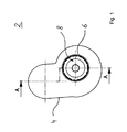
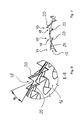
- FIG. 1 is a schematic representation of a mixing device 2 for the aftertreatment of exhaust gases in an exhaust system of an internal combustion engine shown.
- the mixing device 2 upstream of an SCR catalyst fluidically.
- the mixing device 2 comprises a housing 4 and a circular-cylindrical inner tube 6 arranged inside the housing 4.
- a mixing region 8 is formed in the interior of the inner tube 6.
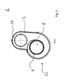
- Fig. 2 shows in a schematic longitudinal sectional view along section line AA, the mixing device 2 from Fig. 1 ,
- the inner tube 6 arranged in the housing 4 can be seen with the mixing area 8 formed in its interior.
- a metering device 10 is attached to an end face of the housing 4.
- the metering device 10 is used to supply a liquid-gas mixture in the mixing region 8 via a nozzle 12 in the form of a spray 14.
- the liquid is a urea solution.
- the inner tube 6 has on its lateral surface 16 access openings 18, through which exhaust gases in the mixing region 8 can be introduced.
- the access openings 18 are provided with exhaust gas guide elements 20, which protrude from the main extension of the lateral surface 16. These exhaust gas guide elements 20 are used, in particular, for the flow guidance of the exhaust gas and, secondly, they prevent the escape of the spray 14 from the mixing region 8.
- the exhaust gas guide elements 20 are here formed integrally on the lateral surface 16 of the inner tube 6, which allows a simple and cost-effective production.
- the number of access openings 18 decreases steadily toward the axial end of the inner tube 6 facing away from the metering device 10.
- the distance between two adjacent access openings 18 increases in the axial direction and in the circumferential direction to the axial end of the inner tube 6 facing away from the metering device 10.
- a decrease in the passage cross section formed by the access openings 18 to the axial end of the inner tube 6 facing away from the metering device 10 is realized.
- Fig. 2 to recognize that the access openings 18 are "twisted out" about an aligned in the direction of the longitudinal center axis of the inner tube 6 course.
- the housing 4 comprises a spiral-shaped housing section 20 which extends along all access openings 18 of the inner tube 6, that is, all access openings 18 of the inner tube 6 are arranged within this spiral housing section 20.
- a circular-cylindrical exhaust gas inlet pipe 26 extends into the housing 4.
- the exhaust gas inlet pipe 26 is guided through the inlet opening 24 into the housing 4.
- the outer diameter of the exhaust gas inlet pipe 26 substantially corresponds to the diameter of the inlet opening 24.
- the longitudinal center axis of the exhaust gas inlet pipe 26 and the longitudinal center axis of the inner tube 6 are aligned parallel to each other and the exhaust gas inlet pipe 26 extends axially along the entire spiral housing portion 22.
- the outlet openings 28 are arranged completely on the peripheral surface 30 of the exhaust gas inlet pipe 26 and have a circular geometry.
- an exhaust gas feedstream 32 fed to the mixing device 2 initially flows via the exhaust gas inlet pipe 26 in the direction of the housing 4 and flows via the outlet openings 28 into the spiral housing section 22.
- the exhaust gas feedstream 32 thus exits the exhaust gas inlet pipe 26 through the outlet openings 28 is "deflected" from an axial direction in a radial direction or at least one radial velocity component is granted to it.
- the exhaust gas feedstream 32 is supplied relatively homogeneously to the spiral-shaped housing section 22 along the entire section of the exhaust gas inlet tube 26 provided with outlet openings 28.
- the spiral-shaped housing section 22 extends along all the outlet openings 28 and in particular along all the access openings 18 ensures that approximately the same flow and pressure conditions prevail on the lateral surface 16 of the inner tube 6 along the section provided with access openings 18.
- a uniform supply of partial exhaust gas streams takes place via the inlet openings 18 into the mixing area 8 and rotationally symmetrical flow conditions can form in the mixing area 8.
- the spray 14 can spread homogeneously in the mixing region 8, since there are approximately uniform flow and pressure conditions, in particular in the circumferential direction about the central main flow axis of the spray 14, which essentially corresponds to the longitudinal central axis of the inner tube 6 in such an arrangement. This ensures a homogeneous mixing of the spray 14 with the exhaust gas supplied via the inlet openings 18 in the form of exhaust partial streams.
- the exhaust gas inflow 32 which flows axially from the axial direction into the exhaust gas inlet pipe 26 and flows axially to the axial end facing away from the metering device 10, can at least temporarily accumulate in this end region of the exhaust gas inlet pipe 26, the exhaust gas volume flow flowing through the outlet openings 28 flows are in this area, at least temporarily greater than the exhaust gas volume flow, which flows through the outlet openings 28 of a dosing device nearer area.
- a partial deflection of the exhaust gas streams flowing through the inlet openings 18 toward the main injection direction of the spray 14 is caused by the illustrated orientation of the access openings 18 and thus in particular of the respective exhaust gas guide elements 20.
- the exhaust partial streams deflected in particular in the area close to the dosing device thus receive a certain velocity component running in the main injection direction of the dosing device 10. This contributes in addition to a homogeneous mixing of the spray 14 with the exhaust gas, since no or only a very small deflection of the spray 14 takes place, in particular in the area near the dosing device.
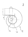
- Fig. 3 shows in a schematic cross-sectional view along section line BB of the mixing device Fig. 2 ,
- the arrangement of the inner tube 6 in the spiral-shaped housing section 22 can be seen. Due to the spiral shape in the circumferential direction caused by volume reduction of the gap between the inner tube 6 and housing wall, it is helped that prevail on the outer circumferential surface 8 of the inner tube 6 along the circumference approximately equal pressure and flow conditions, whereby a uniform possible supply of the exhaust gas in the mixing area 8 can take place.
- Fig. 4 is shown in a schematic representation of a spiral housing portion 22 of an alternative embodiment.
- the inner tube 6 is arranged in the spiral-shaped housing section 22 such that in the circumferential direction between the inner tube 6 and the housing wall a distance s dependent on the course of the spiral shape is always formed.
- a distance s dependent on the course of the spiral shape is always formed.
- This further contributes positively to a homogeneous flow pattern through the spiral-shaped housing portion 22 at.
- r is the radius of curvature
- D is the diameter of the inner tube 6
- s is the distance of the lateral surface 8 of the inner tube 6 from the housing wall of the helical housing 22
- A is the cross-section of the inflow opening of the helical housing.
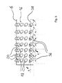
- Fig. 5 shows a schematic representation of an inner tube 6 in a further embodiment.
- the arranged on the lateral surface 16 of the inner tube 6 access openings 18 and the integrally formed at the inlet openings 18 exhaust gas guide elements 20 are shown.
- the access openings 18 and the exhaust gas guide elements 20 are "twisted out" from a course oriented in the direction of the longitudinal central axis of the inner tube 6 by an orientation angle ⁇ .
- the orientation angle ⁇ is enclosed between an opening axis 36 of an exhaust gas guide element 20 and a central longitudinal plane 38 of the inner tube 6 extending through the access opening 18 of the exhaust gas guide element 20.
- the central longitudinal plane 38 extends on the one hand through the center of the respective access opening 18 and on the other by the longitudinal central axis of the inner tube 6 and extends along this longitudinal central axis.
- the inlet openings 18 and in particular the exhaust gas elements 20 cause a certain deflection of the exhaust gas flowing through the access openings 18 exhaust partial flow back to the main injection direction of a metering device 10.
- the orientation angle ⁇ takes axially to the right that is, axially towards an end facing away from a metering device 10, toward.
- the size of the orientation angle ⁇ and in particular the increase axially to the right, is dependent in particular on the metering device 10 and nozzle 12 used in the individual case, as well as on the exhaust gas volume flows which flow through the access openings 18 into the mixing region 8 of the inner tube 6.
- Fig. 6 shows in a schematic longitudinal sectional view along section line EE an enlarged section of the inner tube Fig. 5 ,
- the arranged on the lateral surface 16 of the inner tube 6 access openings 18 and in particular the integrally formed at the inlet openings 18 exhaust gas guide elements 20 can be seen.
- an exhaust gas guide element 20 extends into a mixing region 8 and a further exhaust gas guide element 20 extends into a gap between the lateral surface 16 of the inner tube 6 and a housing wall of a housing 4, in which the inner tube 6 is arranged.
- the respective two exhaust gas guide elements 20 of an access opening 18 are shaped in such a way that they "close off” the access opening as opaque as possible, viewed radially from the longitudinal center axis of the inner tube 6. In this way, leakage of a metering device 10 into a mixing region 8 formed in the interior of the inner tube 6 is prevented particularly effectively.
- the illustrated exhaust elements 20 are in this case at an inclination angle ⁇ from the base surface of the inner tube 6, ie from the lateral surface 8 without consideration of the exhaust elements 20, from.
- FIG. 7 are in a schematic longitudinal sectional view of various embodiments of a Abgasleitelements 20 shown, which are arranged on access openings 18 of a lateral surface 16 of an inner tube 6, which is installed in a housing 4.
- V1 only one exhaust gas guide element 20 is arranged on an access opening 18, which extends into a gap between the lateral surface 16 and a housing wall of the housing 4.
- FIG. 2 shows an inlet opening 18, on which an exhaust gas guide element 20 is arranged, which extends into a mixing area 8 formed inside an inner tube 6.
- V3 is the same as in Fig. 6 illustrated embodiment.
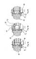
- Fig. 8 shows a schematic longitudinal sectional view of a mixing device 2 in an alternative embodiment.
- the mixing device 2 substantially corresponds to in Fig. 1 to Fig. 3 shown mixing device.
- the distance between two axially adjacent outlet openings 28 of the exhaust gas inlet pipe 26 increases in the axial direction to the axial end of the exhaust gas inlet pipe 26 facing away from the inlet opening 24. Consequently, the number of outlet openings 28 to the inlet opening 24 facing away from the end down. This ensures that the exhaust gas inflow 32 flowing into the exhaust gas inlet pipe 26 flows as homogeneously as possible into the spiral-shaped housing section 22 along the entire section of the exhaust gas inlet pipe 26 provided with outlet openings 28.
- the lateral surface 16 of the inner tube 6 in the region close to the metering device has a circumferential annular gap which serves as a bypass channel 40 for the exhaust gas.
- a guide element 42 is arranged on and coaxially with the metering device 10 and protrudes axially into the mixing region 8 of the inner tube 6. The guide element 42 prevents the spray 14 from being exposed to the exhaust gas partial flow passing through the bypass passage 40 in the area close to the metering device. The guide element 42 further redirects this partial exhaust gas flow in the axial main injection direction.
- the guide element 42 is annular and preferably rotationally symmetrical and formed in its cross section on its outer surface to the dosing device 10 facing away from the end tapered.
- Fig. 9a - 9c show in schematic longitudinal sectional views of various embodiments of a guide element 42 and an inner tube 6 of an enlarged section C from Fig. 8 ,
- the differently configured access openings 18 can be seen.
- the guide elements 42 are designed differently, in particular with respect to their axial and / or radial extent.
- the axial extent of the metering device 10 facing away from the end portion 44 of in Fig. 9b shown guide element 42 is relatively large.
- contact or wetting of the metering device 10 facing away, radially inwardly end portion 44 of the guide element 42 can be realized with the spray 14.
- a slight and / or temporary wetting of the inner wall 46 of the guide element 42 is particularly advantageous in the exhaust gas flowed through state.
- the metering device 10 usually works temporarily. Thus, during the non-injection periods, a "degradation" of the liquid located on the inner wall 46 of the guide element 42 can be achieved.
- the effect is favored by the fact that the guide element 42 is thin-walled and / or is heated on the outside by the partial exhaust gas stream flowing through the bypass channel 40, so that the liquid located on the wall sections of the inner wall 46 also heats up. This heat facilitates the separation effect and splitting effect (secondary rupture) of the liquid droplets that lie on the inside of the guide element 42.
- the mixing function of the mixing device 2 is further promoted by the targeted slight temporary wall contact of the spray 14.
- the degree of temporary adhesion of the liquid On the interpretation of the axial extent of the guide element 42 and in particular its end portion 44 remote from the metering device 10 can be adjusted in a structurally simple and effective manner, the degree of temporary adhesion of the liquid.
- the metering device 10 and thus the spray angle and the density of the liquid is specified. These parameters affect the propagation characteristics of the spray 14 depending on the exhaust gas volumetric flow. If now a liquid with a different density and / or a metering device 10 with a different spray angle are installed, then it is sufficient if the mixing device 2 is adjusted by changing the axial extent of the guide element 42 and in particular of the metering device 10 facing away from end region 44 to to adjust the effect described above (secondary break).
Landscapes
- Chemical & Material Sciences (AREA)
- Engineering & Computer Science (AREA)
- Chemical Kinetics & Catalysis (AREA)
- Combustion & Propulsion (AREA)
- Mechanical Engineering (AREA)
- General Engineering & Computer Science (AREA)
- Health & Medical Sciences (AREA)
- Toxicology (AREA)
- Exhaust Gas After Treatment (AREA)
Applications Claiming Priority (1)
| Application Number | Priority Date | Filing Date | Title |
|---|---|---|---|
| DE102012014334.6A DE102012014334A1 (de) | 2012-07-20 | 2012-07-20 | Mischvorrichtung zur Nachbehandlung von Abgasen |
Publications (3)
| Publication Number | Publication Date |
|---|---|
| EP2687697A2 true EP2687697A2 (fr) | 2014-01-22 |
| EP2687697A3 EP2687697A3 (fr) | 2017-06-28 |
| EP2687697B1 EP2687697B1 (fr) | 2022-07-06 |
Family
ID=48444031
Family Applications (1)
| Application Number | Title | Priority Date | Filing Date |
|---|---|---|---|
| EP13002561.2A Active EP2687697B1 (fr) | 2012-07-20 | 2013-05-16 | Dispositif de mélange pour le post-traitement de gaz d'échappement |
Country Status (5)
| Country | Link |
|---|---|
| EP (1) | EP2687697B1 (fr) |
| CN (1) | CN103573351B (fr) |
| BR (1) | BR102013018004B1 (fr) |
| DE (1) | DE102012014334A1 (fr) |
| RU (1) | RU2628849C2 (fr) |
Cited By (9)
| Publication number | Priority date | Publication date | Assignee | Title |
|---|---|---|---|---|
| DE202014102872U1 (de) | 2014-06-10 | 2014-07-09 | Tenneco Gmbh | Abgasmischer |
| JP2015167946A (ja) * | 2014-03-06 | 2015-09-28 | 有限会社トリビオックス・ラボラトリーズ | マイクロナノバブル発生装置 |
| DE102015103303B3 (de) * | 2015-03-06 | 2016-09-01 | Tenneco Gmbh | Mix Box |
| WO2016177361A1 (fr) * | 2015-05-06 | 2016-11-10 | Iav Gmbh Ingenieurgesellschaft Auto Und Verkehr | Dispositif de mélange |
| US9718037B2 (en) | 2014-12-17 | 2017-08-01 | Caterpillar Inc. | Mixing system for aftertreatment system |
| WO2018108755A1 (fr) * | 2016-12-14 | 2018-06-21 | Perkins Engines Company Limited | Mélangeur de tuyaux pour système de post-traitement |
| CN111672263A (zh) * | 2020-05-23 | 2020-09-18 | 江西馨源香料有限公司 | 一种应用于香料废气处理装置 |
| CN113056595A (zh) * | 2018-11-20 | 2021-06-29 | 罗伯特·博世有限公司 | 废气后处理装置 |
| CN115608102A (zh) * | 2022-01-27 | 2023-01-17 | 江苏希捷新能源工程技术有限公司 | 一种核电站废气处理系统的使用方法 |
Families Citing this family (11)
| Publication number | Priority date | Publication date | Assignee | Title |
|---|---|---|---|---|
| DE102013114111A1 (de) | 2013-12-16 | 2015-06-18 | Tenneco Gmbh | Mischrohranordnung mit Gehäuse |
| DE102015002974A1 (de) | 2015-03-10 | 2016-09-15 | Man Truck & Bus Ag | Vorrichtung zur Nachbehandlung von Abgas eines Kraftfahrzeugs |
| US10040028B2 (en) * | 2015-11-04 | 2018-08-07 | Ford Global Technologies, Llc | Methods and systems for a mixer |
| DE102016224617A1 (de) * | 2016-12-09 | 2018-06-14 | Man Diesel & Turbo Se | Mischvorrichtung für ein Abgasnachbehandlungssystem, Abgasnachbehandlungssystem und Brennkraftmaschine |
| CN108979801A (zh) * | 2017-07-27 | 2018-12-11 | 天纳克(苏州)排放系统有限公司 | 发动机排气后处理混合装置 |
| WO2019104364A1 (fr) * | 2017-12-01 | 2019-06-06 | Avl List Gmbh | Système de post-traitement de gaz d'échappement |
| CN107939488B (zh) * | 2017-12-23 | 2020-03-17 | 无锡威孚力达催化净化器有限责任公司 | 车用尾气处理用尿素混合装置 |
| JP6787606B1 (ja) * | 2019-08-07 | 2020-11-18 | 日新工業株式会社 | 排気浄化装置、流路形成部材、及び筒状部材 |
| JP7752768B2 (ja) * | 2022-12-06 | 2025-10-10 | 株式会社三五 | 排気浄化装置 |
| FR3143667A1 (fr) * | 2022-12-15 | 2024-06-21 | Faurecia Systemes D'echappement | Mélangeur à vortex, destiné à équiper une ligne d’échappement de moteur thermique |
| GB2644168A (en) * | 2024-09-13 | 2026-03-25 | Perkins Engines Co Ltd | Exhaust fluid injector |
Citations (1)
| Publication number | Priority date | Publication date | Assignee | Title |
|---|---|---|---|---|
| DE4203807A1 (de) | 1990-11-29 | 1993-08-12 | Man Nutzfahrzeuge Ag | Vorrichtung zur katalytischen no(pfeil abwaerts)x(pfeil abwaerts)-reduktion |
Family Cites Families (12)
| Publication number | Priority date | Publication date | Assignee | Title |
|---|---|---|---|---|
| FR1323501A (fr) * | 1956-10-17 | 1963-04-12 | Appareil mélangeur atomiseur | |
| DE4012411A1 (de) * | 1990-04-19 | 1991-10-24 | Webasto Ag Fahrzeugtechnik | Mit abgas einer brennkraftmaschine betreibbarer brenner zur regenerierung einer partikelfiltereinrichtung |
| DE19913462A1 (de) * | 1999-03-25 | 2000-09-28 | Man Nutzfahrzeuge Ag | Verfahren zur thermischen Hydrolyse und Dosierung von Harnstoff bzw. wässriger Harnstofflösung in einem Reaktor |
| US6722123B2 (en) * | 2001-10-17 | 2004-04-20 | Fleetguard, Inc. | Exhaust aftertreatment device, including chemical mixing and acoustic effects |
| RU2362024C1 (ru) * | 2005-04-13 | 2009-07-20 | Грундфос Нонокс А/С | Смесительное устройство для смешивания мочевины и воздуха, двигатель, содержащий смесительное устройство, и транспортное средство |
| DE102009053950A1 (de) * | 2009-11-19 | 2011-05-26 | Man Nutzfahrzeuge Aktiengesellschaft | Vorrichtung zur Nachbehandlung von Abgasen von Brennkraftmaschinen |
| ES2434865T3 (es) * | 2009-12-16 | 2013-12-17 | Iveco Motorenforschung Ag | Procedimiento para dosificar un agente reductor a base de urea en una corriente de escape de gas. |
| US8539761B2 (en) * | 2010-01-12 | 2013-09-24 | Donaldson Company, Inc. | Flow device for exhaust treatment system |
| EP3267005B2 (fr) * | 2010-06-22 | 2023-12-27 | Donaldson Company, Inc. | Dispositif de post-traitement d'échappement |
| DE102010056314A1 (de) * | 2010-12-27 | 2012-06-28 | Friedrich Boysen Gmbh & Co. Kg | Vorrichtung zum Verteilen von Fluiden in Abgasanlagen |
| CN202360191U (zh) * | 2011-09-26 | 2012-08-01 | 杭州银轮科技有限公司 | 一种用于柴油机尾气处理的scr催化转化器 |
| CN102671322A (zh) * | 2012-06-06 | 2012-09-19 | 孟欣佳 | 一种空气过滤器 |
-
2012
- 2012-07-20 DE DE102012014334.6A patent/DE102012014334A1/de not_active Withdrawn
-
2013
- 2013-05-16 EP EP13002561.2A patent/EP2687697B1/fr active Active
- 2013-07-15 BR BR102013018004-1A patent/BR102013018004B1/pt active IP Right Grant
- 2013-07-19 RU RU2013133962A patent/RU2628849C2/ru active
- 2013-07-22 CN CN201310307825.3A patent/CN103573351B/zh active Active
Patent Citations (1)
| Publication number | Priority date | Publication date | Assignee | Title |
|---|---|---|---|---|
| DE4203807A1 (de) | 1990-11-29 | 1993-08-12 | Man Nutzfahrzeuge Ag | Vorrichtung zur katalytischen no(pfeil abwaerts)x(pfeil abwaerts)-reduktion |
Cited By (16)
| Publication number | Priority date | Publication date | Assignee | Title |
|---|---|---|---|---|
| JP2015167946A (ja) * | 2014-03-06 | 2015-09-28 | 有限会社トリビオックス・ラボラトリーズ | マイクロナノバブル発生装置 |
| DE102014108809B3 (de) * | 2014-06-10 | 2015-06-25 | Tenneco Gmbh | Abgasmischer |
| DE202014102872U1 (de) | 2014-06-10 | 2014-07-09 | Tenneco Gmbh | Abgasmischer |
| US9957870B2 (en) | 2014-06-10 | 2018-05-01 | Tenneco Gmbh | Exhaust-gas mixer |
| DE102014108809C5 (de) | 2014-06-10 | 2019-04-25 | Tenneco Gmbh | Abgasmischer |
| US9718037B2 (en) | 2014-12-17 | 2017-08-01 | Caterpillar Inc. | Mixing system for aftertreatment system |
| EP3265656B1 (fr) * | 2015-03-06 | 2020-02-19 | Tenneco GmbH | Mélangeur |
| DE102015103303B3 (de) * | 2015-03-06 | 2016-09-01 | Tenneco Gmbh | Mix Box |
| US10626773B2 (en) | 2015-03-06 | 2020-04-21 | Tenneco Gmbh | Mix box |
| WO2016177361A1 (fr) * | 2015-05-06 | 2016-11-10 | Iav Gmbh Ingenieurgesellschaft Auto Und Verkehr | Dispositif de mélange |
| WO2018108755A1 (fr) * | 2016-12-14 | 2018-06-21 | Perkins Engines Company Limited | Mélangeur de tuyaux pour système de post-traitement |
| US10662851B2 (en) | 2016-12-14 | 2020-05-26 | Perkins Engines Company Limited | Pipe mixer for an aftertreatment system |
| CN113056595A (zh) * | 2018-11-20 | 2021-06-29 | 罗伯特·博世有限公司 | 废气后处理装置 |
| CN111672263A (zh) * | 2020-05-23 | 2020-09-18 | 江西馨源香料有限公司 | 一种应用于香料废气处理装置 |
| CN115608102A (zh) * | 2022-01-27 | 2023-01-17 | 江苏希捷新能源工程技术有限公司 | 一种核电站废气处理系统的使用方法 |
| CN115608102B (zh) * | 2022-01-27 | 2023-11-17 | 江苏希捷新能源工程技术有限公司 | 一种核电站废气处理系统的使用方法 |
Also Published As
| Publication number | Publication date |
|---|---|
| RU2013133962A (ru) | 2015-01-27 |
| BR102013018004A2 (pt) | 2015-06-30 |
| DE102012014334A1 (de) | 2014-05-15 |
| BR102013018004B1 (pt) | 2021-05-04 |
| EP2687697A3 (fr) | 2017-06-28 |
| RU2628849C2 (ru) | 2017-08-22 |
| EP2687697B1 (fr) | 2022-07-06 |
| CN103573351B (zh) | 2019-08-06 |
| CN103573351A (zh) | 2014-02-12 |
Similar Documents
| Publication | Publication Date | Title |
|---|---|---|
| EP2687697B1 (fr) | Dispositif de mélange pour le post-traitement de gaz d'échappement | |
| DE102020124106A1 (de) | Kraftfahrzeugabgasnachbehandlungssystem | |
| EP2598730B1 (fr) | Appareil de traitement des gaz d'échappement | |
| EP2691618B1 (fr) | Unité de traitement de gaz d'échappement compacte comprenant une zone de mélange et procédé pour mélanger des gaz d'échappement | |
| EP2266681B1 (fr) | Installation de gaz d'échappement dotée d'une amenée de moyen de réduction et d'un élément de filtre avec un catalyseur SCR | |
| EP3478947B1 (fr) | Dispositif mélangeur pour un système de post-traitement des gaz d'échappement d'un véhicule à moteur, système de post-traitement des gaz d'échappement et véhicule à moteur | |
| EP2687286B1 (fr) | Dispositif de mélange pour le post-traitement de gaz d'échappement | |
| DE102011077156B4 (de) | Abgasanlage und Injektionsmodul | |
| EP2570178B1 (fr) | Dispositif de mélange | |
| DE112020004364T5 (de) | Abgas- und reduktionsmittelmischer für ein nachbehandlungssystem | |
| DE112016000450T5 (de) | Abgasnachbehandlungssystem mit einer Mischeranordnung | |
| DE112017007124T5 (de) | Injektorsprühschutz | |
| DE102008048796A1 (de) | Abgasreinigungssystem für Dieselmotoren | |
| DE202021104734U1 (de) | Mischer und Abgassystem mit solchem Mischer | |
| EP2148053B1 (fr) | Agencement de catalyseurs destiné au nettoyage d'un flux de gaz d'échappement | |
| EP3443209B1 (fr) | Dispositif de post-traitement des gaz d'échappement doté d'un catalyseur et d'un dispositif de mélange | |
| WO2013010700A1 (fr) | Agencement permettant d'introduire un additif dans un flux de gaz | |
| DE102011013335A1 (de) | Abgasanlage einer Brennkraftmaschine | |
| EP2334916B1 (fr) | Dispositif et procédé d'épuration de gaz d'échappement au moyen d'un agent reducteur | |
| EP3752721B1 (fr) | Dispositif de retraitement de gaz d'échappement permettant l'introduction dosée d'un agent de retraitement de gaz d'échappement | |
| EP2325450B1 (fr) | Dispositif de post-traitement de gaz d'échappement d'un moteur à combustion interne | |
| WO2017137032A1 (fr) | Mélangeur servant à mélanger un flux de gaz d'échappement d'un moteur à combustion interne et système d'échappement | |
| DE102015015029A1 (de) | Abgasunterstütztes Zersetzungsreaktorrohr | |
| DE102020201727A1 (de) | System und Verfahren zur Abgasnachbehandlung | |
| DE102008022998A1 (de) | Vorrichtung und Verfahren zur Reinigung von Abgasen für einen Abgasstrang einer Brennkraftmaschine |
Legal Events
| Date | Code | Title | Description |
|---|---|---|---|
| PUAI | Public reference made under article 153(3) epc to a published international application that has entered the european phase |
Free format text: ORIGINAL CODE: 0009012 |
|
| AK | Designated contracting states |
Kind code of ref document: A2 Designated state(s): AL AT BE BG CH CY CZ DE DK EE ES FI FR GB GR HR HU IE IS IT LI LT LU LV MC MK MT NL NO PL PT RO RS SE SI SK SM TR |
|
| AX | Request for extension of the european patent |
Extension state: BA ME |
|
| PUAL | Search report despatched |
Free format text: ORIGINAL CODE: 0009013 |
|
| AK | Designated contracting states |
Kind code of ref document: A3 Designated state(s): AL AT BE BG CH CY CZ DE DK EE ES FI FR GB GR HR HU IE IS IT LI LT LU LV MC MK MT NL NO PL PT RO RS SE SI SK SM TR |
|
| AX | Request for extension of the european patent |
Extension state: BA ME |
|
| RIC1 | Information provided on ipc code assigned before grant |
Ipc: F01N 3/28 20060101ALI20170522BHEP Ipc: F01N 3/20 20060101ALI20170522BHEP Ipc: F01N 3/025 20060101ALI20170522BHEP Ipc: F01N 3/24 20060101ALI20170522BHEP Ipc: B01F 5/04 20060101ALI20170522BHEP Ipc: F01N 3/36 20060101AFI20170522BHEP |
|
| STAA | Information on the status of an ep patent application or granted ep patent |
Free format text: STATUS: REQUEST FOR EXAMINATION WAS MADE |
|
| 17P | Request for examination filed |
Effective date: 20171011 |
|
| RAP1 | Party data changed (applicant data changed or rights of an application transferred) |
Owner name: MAN TRUCK & BUS SE |
|
| STAA | Information on the status of an ep patent application or granted ep patent |
Free format text: STATUS: EXAMINATION IS IN PROGRESS |
|
| 17Q | First examination report despatched |
Effective date: 20210223 |
|
| REG | Reference to a national code |
Ref country code: DE Ref legal event code: R079 Ref document number: 502013016178 Country of ref document: DE Free format text: PREVIOUS MAIN CLASS: F01N0003360000 Ipc: B01F0025310000 |
|
| GRAP | Despatch of communication of intention to grant a patent |
Free format text: ORIGINAL CODE: EPIDOSNIGR1 |
|
| STAA | Information on the status of an ep patent application or granted ep patent |
Free format text: STATUS: GRANT OF PATENT IS INTENDED |
|
| RIC1 | Information provided on ipc code assigned before grant |
Ipc: F01N 3/24 20060101ALI20220106BHEP Ipc: F01N 3/20 20060101ALI20220106BHEP Ipc: F01N 3/025 20060101ALI20220106BHEP Ipc: F01N 3/28 20060101ALI20220106BHEP Ipc: F01N 3/36 20060101ALI20220106BHEP Ipc: B01F 25/31 20220101AFI20220106BHEP |
|
| INTG | Intention to grant announced |
Effective date: 20220120 |
|
| GRAS | Grant fee paid |
Free format text: ORIGINAL CODE: EPIDOSNIGR3 |
|
| GRAA | (expected) grant |
Free format text: ORIGINAL CODE: 0009210 |
|
| STAA | Information on the status of an ep patent application or granted ep patent |
Free format text: STATUS: THE PATENT HAS BEEN GRANTED |
|
| AK | Designated contracting states |
Kind code of ref document: B1 Designated state(s): AL AT BE BG CH CY CZ DE DK EE ES FI FR GB GR HR HU IE IS IT LI LT LU LV MC MK MT NL NO PL PT RO RS SE SI SK SM TR |
|
| REG | Reference to a national code |
Ref country code: GB Ref legal event code: FG4D Free format text: NOT ENGLISH |
|
| REG | Reference to a national code |
Ref country code: AT Ref legal event code: REF Ref document number: 1502461 Country of ref document: AT Kind code of ref document: T Effective date: 20220715 Ref country code: CH Ref legal event code: EP |
|
| REG | Reference to a national code |
Ref country code: DE Ref legal event code: R096 Ref document number: 502013016178 Country of ref document: DE |
|
| REG | Reference to a national code |
Ref country code: IE Ref legal event code: FG4D Free format text: LANGUAGE OF EP DOCUMENT: GERMAN |
|
| REG | Reference to a national code |
Ref country code: NL Ref legal event code: FP |
|
| REG | Reference to a national code |
Ref country code: SE Ref legal event code: TRGR |
|
| REG | Reference to a national code |
Ref country code: LT Ref legal event code: MG9D |
|
| PG25 | Lapsed in a contracting state [announced via postgrant information from national office to epo] |
Ref country code: RS Free format text: LAPSE BECAUSE OF FAILURE TO SUBMIT A TRANSLATION OF THE DESCRIPTION OR TO PAY THE FEE WITHIN THE PRESCRIBED TIME-LIMIT Effective date: 20220706 Ref country code: PT Free format text: LAPSE BECAUSE OF FAILURE TO SUBMIT A TRANSLATION OF THE DESCRIPTION OR TO PAY THE FEE WITHIN THE PRESCRIBED TIME-LIMIT Effective date: 20221107 Ref country code: NO Free format text: LAPSE BECAUSE OF FAILURE TO SUBMIT A TRANSLATION OF THE DESCRIPTION OR TO PAY THE FEE WITHIN THE PRESCRIBED TIME-LIMIT Effective date: 20221006 Ref country code: LV Free format text: LAPSE BECAUSE OF FAILURE TO SUBMIT A TRANSLATION OF THE DESCRIPTION OR TO PAY THE FEE WITHIN THE PRESCRIBED TIME-LIMIT Effective date: 20220706 Ref country code: LT Free format text: LAPSE BECAUSE OF FAILURE TO SUBMIT A TRANSLATION OF THE DESCRIPTION OR TO PAY THE FEE WITHIN THE PRESCRIBED TIME-LIMIT Effective date: 20220706 Ref country code: FI Free format text: LAPSE BECAUSE OF FAILURE TO SUBMIT A TRANSLATION OF THE DESCRIPTION OR TO PAY THE FEE WITHIN THE PRESCRIBED TIME-LIMIT Effective date: 20220706 Ref country code: ES Free format text: LAPSE BECAUSE OF FAILURE TO SUBMIT A TRANSLATION OF THE DESCRIPTION OR TO PAY THE FEE WITHIN THE PRESCRIBED TIME-LIMIT Effective date: 20220706 |
|
| PG25 | Lapsed in a contracting state [announced via postgrant information from national office to epo] |
Ref country code: PL Free format text: LAPSE BECAUSE OF FAILURE TO SUBMIT A TRANSLATION OF THE DESCRIPTION OR TO PAY THE FEE WITHIN THE PRESCRIBED TIME-LIMIT Effective date: 20220706 Ref country code: IS Free format text: LAPSE BECAUSE OF FAILURE TO SUBMIT A TRANSLATION OF THE DESCRIPTION OR TO PAY THE FEE WITHIN THE PRESCRIBED TIME-LIMIT Effective date: 20221106 Ref country code: HR Free format text: LAPSE BECAUSE OF FAILURE TO SUBMIT A TRANSLATION OF THE DESCRIPTION OR TO PAY THE FEE WITHIN THE PRESCRIBED TIME-LIMIT Effective date: 20220706 Ref country code: GR Free format text: LAPSE BECAUSE OF FAILURE TO SUBMIT A TRANSLATION OF THE DESCRIPTION OR TO PAY THE FEE WITHIN THE PRESCRIBED TIME-LIMIT Effective date: 20221007 |
|
| REG | Reference to a national code |
Ref country code: DE Ref legal event code: R097 Ref document number: 502013016178 Country of ref document: DE |
|
| PG25 | Lapsed in a contracting state [announced via postgrant information from national office to epo] |
Ref country code: SM Free format text: LAPSE BECAUSE OF FAILURE TO SUBMIT A TRANSLATION OF THE DESCRIPTION OR TO PAY THE FEE WITHIN THE PRESCRIBED TIME-LIMIT Effective date: 20220706 Ref country code: RO Free format text: LAPSE BECAUSE OF FAILURE TO SUBMIT A TRANSLATION OF THE DESCRIPTION OR TO PAY THE FEE WITHIN THE PRESCRIBED TIME-LIMIT Effective date: 20220706 Ref country code: DK Free format text: LAPSE BECAUSE OF FAILURE TO SUBMIT A TRANSLATION OF THE DESCRIPTION OR TO PAY THE FEE WITHIN THE PRESCRIBED TIME-LIMIT Effective date: 20220706 Ref country code: CZ Free format text: LAPSE BECAUSE OF FAILURE TO SUBMIT A TRANSLATION OF THE DESCRIPTION OR TO PAY THE FEE WITHIN THE PRESCRIBED TIME-LIMIT Effective date: 20220706 |
|
| PLBE | No opposition filed within time limit |
Free format text: ORIGINAL CODE: 0009261 |
|
| STAA | Information on the status of an ep patent application or granted ep patent |
Free format text: STATUS: NO OPPOSITION FILED WITHIN TIME LIMIT |
|
| PG25 | Lapsed in a contracting state [announced via postgrant information from national office to epo] |
Ref country code: SK Free format text: LAPSE BECAUSE OF FAILURE TO SUBMIT A TRANSLATION OF THE DESCRIPTION OR TO PAY THE FEE WITHIN THE PRESCRIBED TIME-LIMIT Effective date: 20220706 Ref country code: EE Free format text: LAPSE BECAUSE OF FAILURE TO SUBMIT A TRANSLATION OF THE DESCRIPTION OR TO PAY THE FEE WITHIN THE PRESCRIBED TIME-LIMIT Effective date: 20220706 |
|
| 26N | No opposition filed |
Effective date: 20230411 |
|
| PG25 | Lapsed in a contracting state [announced via postgrant information from national office to epo] |
Ref country code: AL Free format text: LAPSE BECAUSE OF FAILURE TO SUBMIT A TRANSLATION OF THE DESCRIPTION OR TO PAY THE FEE WITHIN THE PRESCRIBED TIME-LIMIT Effective date: 20220706 |
|
| PG25 | Lapsed in a contracting state [announced via postgrant information from national office to epo] |
Ref country code: SI Free format text: LAPSE BECAUSE OF FAILURE TO SUBMIT A TRANSLATION OF THE DESCRIPTION OR TO PAY THE FEE WITHIN THE PRESCRIBED TIME-LIMIT Effective date: 20220706 |
|
| REG | Reference to a national code |
Ref country code: CH Ref legal event code: PL |
|
| PG25 | Lapsed in a contracting state [announced via postgrant information from national office to epo] |
Ref country code: MC Free format text: LAPSE BECAUSE OF FAILURE TO SUBMIT A TRANSLATION OF THE DESCRIPTION OR TO PAY THE FEE WITHIN THE PRESCRIBED TIME-LIMIT Effective date: 20220706 |
|
| GBPC | Gb: european patent ceased through non-payment of renewal fee |
Effective date: 20230516 |
|
| REG | Reference to a national code |
Ref country code: BE Ref legal event code: MM Effective date: 20230531 |
|
| PG25 | Lapsed in a contracting state [announced via postgrant information from national office to epo] |
Ref country code: MC Free format text: LAPSE BECAUSE OF FAILURE TO SUBMIT A TRANSLATION OF THE DESCRIPTION OR TO PAY THE FEE WITHIN THE PRESCRIBED TIME-LIMIT Effective date: 20220706 Ref country code: LU Free format text: LAPSE BECAUSE OF NON-PAYMENT OF DUE FEES Effective date: 20230516 Ref country code: LI Free format text: LAPSE BECAUSE OF NON-PAYMENT OF DUE FEES Effective date: 20230531 Ref country code: CH Free format text: LAPSE BECAUSE OF NON-PAYMENT OF DUE FEES Effective date: 20230531 |
|
| REG | Reference to a national code |
Ref country code: IE Ref legal event code: MM4A |
|
| PG25 | Lapsed in a contracting state [announced via postgrant information from national office to epo] |
Ref country code: IE Free format text: LAPSE BECAUSE OF NON-PAYMENT OF DUE FEES Effective date: 20230516 |
|
| PG25 | Lapsed in a contracting state [announced via postgrant information from national office to epo] |
Ref country code: IE Free format text: LAPSE BECAUSE OF NON-PAYMENT OF DUE FEES Effective date: 20230516 Ref country code: GB Free format text: LAPSE BECAUSE OF NON-PAYMENT OF DUE FEES Effective date: 20230516 |
|
| PG25 | Lapsed in a contracting state [announced via postgrant information from national office to epo] |
Ref country code: BE Free format text: LAPSE BECAUSE OF NON-PAYMENT OF DUE FEES Effective date: 20230531 |
|
| REG | Reference to a national code |
Ref country code: AT Ref legal event code: MM01 Ref document number: 1502461 Country of ref document: AT Kind code of ref document: T Effective date: 20230516 |
|
| PG25 | Lapsed in a contracting state [announced via postgrant information from national office to epo] |
Ref country code: AT Free format text: LAPSE BECAUSE OF NON-PAYMENT OF DUE FEES Effective date: 20230516 |
|
| PG25 | Lapsed in a contracting state [announced via postgrant information from national office to epo] |
Ref country code: AT Free format text: LAPSE BECAUSE OF NON-PAYMENT OF DUE FEES Effective date: 20230516 |
|
| PG25 | Lapsed in a contracting state [announced via postgrant information from national office to epo] |
Ref country code: BG Free format text: LAPSE BECAUSE OF FAILURE TO SUBMIT A TRANSLATION OF THE DESCRIPTION OR TO PAY THE FEE WITHIN THE PRESCRIBED TIME-LIMIT Effective date: 20220706 |
|
| PG25 | Lapsed in a contracting state [announced via postgrant information from national office to epo] |
Ref country code: BG Free format text: LAPSE BECAUSE OF FAILURE TO SUBMIT A TRANSLATION OF THE DESCRIPTION OR TO PAY THE FEE WITHIN THE PRESCRIBED TIME-LIMIT Effective date: 20220706 |
|
| PGFP | Annual fee paid to national office [announced via postgrant information from national office to epo] |
Ref country code: NL Payment date: 20250526 Year of fee payment: 13 |
|
| PGFP | Annual fee paid to national office [announced via postgrant information from national office to epo] |
Ref country code: DE Payment date: 20250528 Year of fee payment: 13 |
|
| PGFP | Annual fee paid to national office [announced via postgrant information from national office to epo] |
Ref country code: IT Payment date: 20250522 Year of fee payment: 13 |
|
| PGFP | Annual fee paid to national office [announced via postgrant information from national office to epo] |
Ref country code: FR Payment date: 20250526 Year of fee payment: 13 |
|
| PG25 | Lapsed in a contracting state [announced via postgrant information from national office to epo] |
Ref country code: CY Free format text: LAPSE BECAUSE OF FAILURE TO SUBMIT A TRANSLATION OF THE DESCRIPTION OR TO PAY THE FEE WITHIN THE PRESCRIBED TIME-LIMIT; INVALID AB INITIO Effective date: 20130516 |
|
| PGFP | Annual fee paid to national office [announced via postgrant information from national office to epo] |
Ref country code: SE Payment date: 20250526 Year of fee payment: 13 |
|
| PG25 | Lapsed in a contracting state [announced via postgrant information from national office to epo] |
Ref country code: HU Free format text: LAPSE BECAUSE OF FAILURE TO SUBMIT A TRANSLATION OF THE DESCRIPTION OR TO PAY THE FEE WITHIN THE PRESCRIBED TIME-LIMIT; INVALID AB INITIO Effective date: 20130516 |
|
| PG25 | Lapsed in a contracting state [announced via postgrant information from national office to epo] |
Ref country code: TR Free format text: LAPSE BECAUSE OF FAILURE TO SUBMIT A TRANSLATION OF THE DESCRIPTION OR TO PAY THE FEE WITHIN THE PRESCRIBED TIME-LIMIT Effective date: 20220706 |