EP2687732A1 - Élément de retenue pour câbles tendus - Google Patents
Élément de retenue pour câbles tendus Download PDFInfo
- Publication number
- EP2687732A1 EP2687732A1 EP12757813.6A EP12757813A EP2687732A1 EP 2687732 A1 EP2687732 A1 EP 2687732A1 EP 12757813 A EP12757813 A EP 12757813A EP 2687732 A1 EP2687732 A1 EP 2687732A1
- Authority
- EP
- European Patent Office
- Prior art keywords
- cable
- retaining member
- tensioned
- retaining
- cables
- Prior art date
- Legal status (The legal status is an assumption and is not a legal conclusion. Google has not performed a legal analysis and makes no representation as to the accuracy of the status listed.)
- Withdrawn
Links
- 230000014759 maintenance of location Effects 0.000 title abstract description 3
- 230000007246 mechanism Effects 0.000 claims abstract description 17
- 239000007787 solid Substances 0.000 claims description 3
- 230000003100 immobilizing effect Effects 0.000 claims 1
- 230000000717 retained effect Effects 0.000 description 4
- 230000000694 effects Effects 0.000 description 3
- 239000000463 material Substances 0.000 description 3
- 230000001788 irregular Effects 0.000 description 2
- 229910010293 ceramic material Inorganic materials 0.000 description 1
- 230000006866 deterioration Effects 0.000 description 1
Images

Classifications
-
- F—MECHANICAL ENGINEERING; LIGHTING; HEATING; WEAPONS; BLASTING
- F16—ENGINEERING ELEMENTS AND UNITS; GENERAL MEASURES FOR PRODUCING AND MAINTAINING EFFECTIVE FUNCTIONING OF MACHINES OR INSTALLATIONS; THERMAL INSULATION IN GENERAL
- F16G—BELTS, CABLES, OR ROPES, PREDOMINANTLY USED FOR DRIVING PURPOSES; CHAINS; FITTINGS PREDOMINANTLY USED THEREFOR
- F16G11/00—Means for fastening cables or ropes to one another or to other objects; Caps or sleeves for fixing on cables or ropes
- F16G11/10—Quick-acting fastenings; Clamps holding in one direction only
- F16G11/105—Clamps holding in one direction only
- F16G11/108—Clamps holding in one direction only using a ball or a cylinder
-
- F—MECHANICAL ENGINEERING; LIGHTING; HEATING; WEAPONS; BLASTING
- F16—ENGINEERING ELEMENTS AND UNITS; GENERAL MEASURES FOR PRODUCING AND MAINTAINING EFFECTIVE FUNCTIONING OF MACHINES OR INSTALLATIONS; THERMAL INSULATION IN GENERAL
- F16B—DEVICES FOR FASTENING OR SECURING CONSTRUCTIONAL ELEMENTS OR MACHINE PARTS TOGETHER, e.g. NAILS, BOLTS, CIRCLIPS, CLAMPS, CLIPS OR WEDGES; JOINTS OR JOINTING
- F16B2/00—Friction-grip releasable fastenings
- F16B2/02—Clamps, i.e. with gripping action effected by positive means other than the inherent resistance to deformation of the material of the fastening
- F16B2/16—Clamps, i.e. with gripping action effected by positive means other than the inherent resistance to deformation of the material of the fastening using rollers or balls
Definitions
- the present invention relates to the assembly of tensioned cables in any application, proposing a member that allows retaining tensioned cables with respect to securing structures for same under advantageous conditions.
- tensioned cables which are fixed to posts or other securing structures, where the cables must be retained so as to safely withstand the tension thereof.
- the cables to be tensioned are locked at one end to a securing point and from the other end the traction necessary for defining the desired tension is performed with suitable means, the cable being locked at that second end to another securing point under such conditions.
- retaining members For said function of locking the tensioned cables at the securing points, retaining members have been developed which comprise a body provided with longitudinally traversing channels, and there being internally arranged in relation to each of the channels a movable part, such as a ball or a roller, said movable part being pushed by a spring in an oblique direction with respect to the respective channel, such that a cable can pass through each channel in one direction, the cable being locked against movement in the opposite direction as the movable part acting on the channel applies a wedge effect on the cable, which thus allows splicing together two tensioned cables or establishing a retaining abutment of a tensioned cable against a securing structure.
- a movable part such as a ball or a roller
- the movable part intended for locking the cables in said retaining members is usually made of such material, which is nevertheless very fragile and therefore readily breaks in response to certain stresses.
- conventional retaining members of this type generally present an irregular configuration at the ends, such that in the abutment function for retaining tensioned cables, said members initially act as a support that is not stable on the securing structure, the member tilting to a stable support position when the traction means used for tensioning the cable are no longer acting, whereby instantaneously producing a transverse stress component of the cable on the movable locking part, which in some cases breaks due to the effect of that stress component, 4-5% of the members used ultimately breaking, with the subsequent economic repercussion and delay where they are applied.
- the invention proposes a retaining member that allows effectively establishing an abutting lock for tensioned cables at the securing points, said member having features that prevent transmitting harmful stress components from the tensioned cables of application to the part that establishes the lock in said retaining member.
- this retaining member object of the invention comprises a body made of a rigid material, provided with one or two longitudinal traversing channels, and in relation to each conduit there is arranged a movable part which is obliquely pushed by a spring towards the corresponding channel.
- the body of the retaining member is defined, at the ends, with a front that is completely perpendicular to the channel or channels longitudinally traversing said body.
- a retaining member through which a tensioned cable can pass to establish a lock thereof against a post or any other securing structure is thus formed, said retaining member presenting an abutting front defining a planar seating support in the direction of the line of the tensioned cable, such that it establishes a completely stable seat against the securing structure, so the stress of the tensioned cable remains constant in the longitudinal line of the retaining member.
- the retaining member is not subjected to transverse stresses that may affect the part for locking the tensioned cable, whereby preventing said part for locking the tensioned cable from breaking and the retaining member being thus more effective and durable, which allows saving the deterioration percentage and the subsequent damage involved when locking parts in conventional retaining members break.
- the front perpendicular to the channels for the passage of cables in the body of the retaining member is further provided with anti-slip conformations, which ensures fastness of the retaining member in support against the securing structures of the tensioned cables, thereby completely preventing any transverse stress component of the tensioned cables on the retaining member in the function of application.
- Said retaining member object of the invention therefore has very advantageous features for retaining tensioned cables in abutment on securing structures, acquiring its own identity and preferred character with respect to conventional members having the same function of retaining tensioned cables.
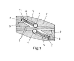
- the object of the invention relates to a retaining member for tensioned cables, retaining them with respect to securing structures (1), of the type comprising a body (2) made of a rigid material along which there extend channels (3) intended for the passage of cables, and in relation to each of said channels (3) there is arranged a mechanism formed by a movable part (4), such as a ball or a roller, which is pushed by a spring (5) obliquely towards the corresponding channel (3), said mechanism being housed in a cavity (6) communicating with the channel (3) and being closed at the other end by a cap (7) where the spring (5) rests.
- a movable part (4) such as a ball or a roller
- each channel (3) there can be passed through each channel (3) one cable (8), which can be introduced in the pushing direction of the movable part (4) against the action of the respective spring (5), such that once the cable (8) goes past the position of the movable part (4), it is locked by said movable part (4) in the reverse direction, because the pressure that that movable part (4) exerts on the cable (8) when being pushed by the spring (5), due to the oblique direction in which that pressure acts, makes the pressure of the movable part on the cable (8) increase when trying to move the cable (8) in reverse, such increase being greater the greater the stress when moving the cable in reverse, which prevents the cable (8) from being able to move in that reverse direction.
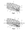
- the retaining member thus formed can be used as an attachment member between two consecutive tensioned cables (8), passing one of the cables (8) in one direction and the other cable in the opposite direction through the respective conduits (3), as observed in Figure 3 , such that upon tensioning the set of the two cables (8), both are locked in the retaining member, which thus acts as a splicing attachment between the mentioned cables (8).
- said retaining member can also be used as a retaining abutment for retaining tensioned cables (8) with respect to securing structures (1), for example in the assembly of tensioned cables (8) for training vines, forming fences or any other application, to that end passing the cable (8) to be retained through any of the channels (3) of the body (2) of the retaining member, as seen in Figure 2 .
- the body (2) of the retaining member is defined, at the ends, with fronts (9) that are completely perpendicular to the channels (3) for the passage of the cables (8) to be retained, as observed in Figure 1 .
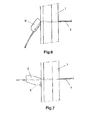
- said body (2) of the retaining member in the abutment function for retaining tensioned cables (8) forms a front seating against the support structure (1), which is completely perpendicular to the line of the tensioned cable (8) of application, as seen in Figure 7 , such that as a result of said planar front support seating, the retaining member is completely stable in its abutment position, the stress of the cable (8) being maintained constant in the direction of tension, without producing transverse stress components.
- the retaining member tilting to find a stable abutment position when loaded with the tension of the cable (8) to be retained is thereby prevented, as the traction means used for tensioning the cable (8) of application no longer act, which is opposite that which occurs with conventional retaining members (10) that have an irregular abutment front which, upon receiving the tension of the tensioned cable (8), adopt an inclined position, as seen in Figure 6 , whereby producing an instantaneous transverse stress component affecting the movable part (4) of the locking mechanism, sometimes causing said part to break.
- Said front (9) perpendicular to the channels (3) for the passage of the cables (8) is further provided with conformations (not depicted), such as projections in the form of teeth, knurling, roughness, etc., that prevent sliding when being supported against the structures (1) in the abutment function of the retaining member, whereby achieving a more effective stability function of the retaining member in the retaining abutment of the tensioned cables (8) to prevent harmful stress components.
- each locking mechanism is provided with an axial pin (11) in the inner portion on which pin (11) the spring (5) of the respective locking mechanism fits, said spring (5) thus being stable in its position and with a guidance improving its action in pushing the respective movable part (4) for the function of locking the cable (8) passing through the corresponding channel (3).
Landscapes
- Engineering & Computer Science (AREA)
- General Engineering & Computer Science (AREA)
- Mechanical Engineering (AREA)
- Supports For Pipes And Cables (AREA)
- Clamps And Clips (AREA)
Applications Claiming Priority (2)
| Application Number | Priority Date | Filing Date | Title |
|---|---|---|---|
| ES201100294A ES2388278B1 (es) | 2011-03-15 | 2011-03-15 | Elemento de retención para cables tensados. |
| PCT/ES2012/000055 WO2012123603A1 (fr) | 2011-03-15 | 2012-03-09 | Élément de retenue pour câbles tendus |
Publications (2)
| Publication Number | Publication Date |
|---|---|
| EP2687732A1 true EP2687732A1 (fr) | 2014-01-22 |
| EP2687732A4 EP2687732A4 (fr) | 2015-07-08 |
Family
ID=46830079
Family Applications (1)
| Application Number | Title | Priority Date | Filing Date |
|---|---|---|---|
| EP12757813.6A Withdrawn EP2687732A4 (fr) | 2011-03-15 | 2012-03-09 | Élément de retenue pour câbles tendus |
Country Status (3)
| Country | Link |
|---|---|
| EP (1) | EP2687732A4 (fr) |
| ES (1) | ES2388278B1 (fr) |
| WO (1) | WO2012123603A1 (fr) |
Families Citing this family (3)
| Publication number | Priority date | Publication date | Assignee | Title |
|---|---|---|---|---|
| CN106640869B (zh) * | 2016-10-11 | 2018-12-14 | 深圳市兆威机电股份有限公司 | 锁紧装置 |
| CN112228432A (zh) * | 2020-10-14 | 2021-01-15 | 迈柯唯医疗设备(苏州)有限公司 | 扶手条快速卡扣机构 |
| EP4050766A3 (fr) | 2021-02-25 | 2022-09-28 | Regal Beloit America, Inc. | Ensemble machine électrique doté d'un cadre de rotor pour fournir un refroidissement |
Family Cites Families (10)
| Publication number | Priority date | Publication date | Assignee | Title |
|---|---|---|---|---|
| US2374875A (en) * | 1943-10-19 | 1945-05-01 | Jay A Mcmurphy | Cable clamp |
| US4216568A (en) * | 1976-01-22 | 1980-08-12 | Anderson Nigel I | Tensioning of metal wires |
| GB9000415D0 (en) * | 1990-01-09 | 1990-03-07 | Gripple Ltd | Connector for wires,etc |
| GB9606155D0 (en) * | 1996-03-23 | 1996-05-29 | Gripple Ltd | Devices for clamping wires etc |
| ES1049506Y (es) * | 2001-06-27 | 2002-04-16 | Morales Tercero S C | Dispositivo perfeccionado para la conexion de cables, alambres y similares. |
| GB0120524D0 (en) * | 2001-08-23 | 2001-10-17 | Gripple Ltd | Suspending equipment |
| US20030115723A1 (en) * | 2001-12-20 | 2003-06-26 | Shuey Alan B. | Releasable cable grip |
| GB0412916D0 (en) * | 2004-06-10 | 2004-07-14 | Gripple Ltd | Securing device for wires |
| ES2284365B2 (es) * | 2005-12-20 | 2008-09-16 | Shiny Works, S.L. | Dispositivo de seguridad para unir y tensar elementos filiformes en general, con mecanismo de alta resistencia guiado en todo su recorrido. |
| PT2109723E (pt) * | 2007-02-08 | 2012-02-08 | Gripple Ltd | Dispositivo de terminação de fio |
-
2011
- 2011-03-15 ES ES201100294A patent/ES2388278B1/es not_active Expired - Fee Related
-
2012
- 2012-03-09 EP EP12757813.6A patent/EP2687732A4/fr not_active Withdrawn
- 2012-03-09 WO PCT/ES2012/000055 patent/WO2012123603A1/fr not_active Ceased
Also Published As
| Publication number | Publication date |
|---|---|
| WO2012123603A1 (fr) | 2012-09-20 |
| ES2388278A1 (es) | 2012-10-11 |
| ES2388278B1 (es) | 2013-06-17 |
| EP2687732A4 (fr) | 2015-07-08 |
Similar Documents
| Publication | Publication Date | Title |
|---|---|---|
| US10640985B2 (en) | Device for fastening a panel-shaped component in a receiving groove of a carrying rail | |
| US9822910B2 (en) | Joint restraint assembly | |
| JP2021038601A (ja) | ネジ棒付き圧着グリップ及びそれを用いた緊張材 | |
| KR0147865B1 (ko) | 지주의 길이 조정장치 | |
| EP2115509A1 (fr) | Éléments d'enfichage pour une connexion optique par fiches | |
| GB2571764A (en) | An assembly and method for attaching two components | |
| US20150043968A1 (en) | Bracket for securing a structural member | |
| AU2015204299B2 (en) | In-line cable tie with flexible head | |
| CN110100116B (zh) | 楔形夹及钢丝 | |
| US20210293265A1 (en) | Joining assembly and securing device for use in a joining assembly | |
| US10156248B2 (en) | Profile connector and profile assembly | |
| EP2848839B1 (fr) | Dispositif de fixation d'un câble métallique | |
| GB2387216A (en) | Shaft assembly safety mechanism | |
| WO2012123603A1 (fr) | Élément de retenue pour câbles tendus | |
| DE102015209904A1 (de) | Überwachungsvorrichtung für eine Sensoranordnung in einem Kraftfahrzeug | |
| KR101890678B1 (ko) | 철근이음장치 | |
| EP2881596B1 (fr) | Cale de montage | |
| US20240200411A1 (en) | Threaded connection for exploration and production of a hydrocarbon well | |
| EP2995746A3 (fr) | Liaison mecanique pour panneaux et procede de montage d'un ressort de verrouillage dans un panneau | |
| US10495133B2 (en) | Captive bolt and retainer | |
| JP4046128B2 (ja) | 部材間継手 | |
| JP2016208661A (ja) | くさびクランプ | |
| KR101579199B1 (ko) | 강재 빔의 손상을 방지하면서 조립 설치되는 강재 빔 보강용 긴장재의 정착구 | |
| JP2004060432A (ja) | Pc鋼材の定着くさび | |
| EP1693576B1 (fr) | Cheville |
Legal Events
| Date | Code | Title | Description |
|---|---|---|---|
| PUAI | Public reference made under article 153(3) epc to a published international application that has entered the european phase |
Free format text: ORIGINAL CODE: 0009012 |
|
| 17P | Request for examination filed |
Effective date: 20131015 |
|
| AK | Designated contracting states |
Kind code of ref document: A1 Designated state(s): AL AT BE BG CH CY CZ DE DK EE ES FI FR GB GR HR HU IE IS IT LI LT LU LV MC MK MT NL NO PL PT RO RS SE SI SK SM TR |
|
| DAX | Request for extension of the european patent (deleted) | ||
| RA4 | Supplementary search report drawn up and despatched (corrected) |
Effective date: 20150610 |
|
| RIC1 | Information provided on ipc code assigned before grant |
Ipc: G05D 15/00 20060101ALI20150603BHEP Ipc: F16G 11/04 20060101ALI20150603BHEP Ipc: F16G 11/10 20060101ALI20150603BHEP Ipc: F16B 2/16 20060101AFI20150603BHEP |
|
| STAA | Information on the status of an ep patent application or granted ep patent |
Free format text: STATUS: THE APPLICATION IS DEEMED TO BE WITHDRAWN |
|
| 18D | Application deemed to be withdrawn |
Effective date: 20160108 |