EP2687827A2 - Magnetisch-induktives Durchflussmessgerät - Google Patents
Magnetisch-induktives Durchflussmessgerät Download PDFInfo
- Publication number
- EP2687827A2 EP2687827A2 EP13003422.6A EP13003422A EP2687827A2 EP 2687827 A2 EP2687827 A2 EP 2687827A2 EP 13003422 A EP13003422 A EP 13003422A EP 2687827 A2 EP2687827 A2 EP 2687827A2
- Authority
- EP
- European Patent Office
- Prior art keywords
- magnetic
- measuring
- measuring tube
- coil
- section
- Prior art date
- Legal status (The legal status is an assumption and is not a legal conclusion. Google has not performed a legal analysis and makes no representation as to the accuracy of the status listed.)
- Granted
Links
Images


Classifications
-
- G—PHYSICS
- G01—MEASURING; TESTING
- G01F—MEASURING VOLUME, VOLUME FLOW, MASS FLOW OR LIQUID LEVEL; METERING BY VOLUME
- G01F1/00—Measuring the volume flow or mass flow of fluid or fluent solid material wherein the fluid passes through a meter in a continuous flow
- G01F1/56—Measuring the volume flow or mass flow of fluid or fluent solid material wherein the fluid passes through a meter in a continuous flow by using electric or magnetic effects
- G01F1/58—Measuring the volume flow or mass flow of fluid or fluent solid material wherein the fluid passes through a meter in a continuous flow by using electric or magnetic effects by electromagnetic flowmeters
- G01F1/588—Measuring the volume flow or mass flow of fluid or fluent solid material wherein the fluid passes through a meter in a continuous flow by using electric or magnetic effects by electromagnetic flowmeters combined constructions of electrodes, coils or magnetic circuits, accessories therefor
Definitions
- the invention relates to a magnetic-inductive flowmeter having at least one measuring tube, wherein the measuring tube has at least one measuring section, with at least one magnetic field generating device for generating a magnetic field in the measuring section of the measuring tube, and with at least two electrodes arranged in the measuring section of the measuring tube for detecting a measuring voltage the magnetic field generating device has at least one magnet coil, preferably arranged outside the measuring section of the measuring tube, with a coil core.
- a measuring tube is preferably used from a non-magnetic material, for example made of plastic or a non-magnetic metal, in the region of a measuring section of the measuring medium or the measuring fluid -.
- a liquid a gas or a mixture of a liquid and solids therein - is electrically isolated from the measurement fluid.
- a magnetic field generated by a magnetic field generating device passes through the measuring tube in the measuring section at least partially substantially perpendicular to the flow direction of the measuring medium. If the measuring medium has a minimum electrical conductivity, its charge carriers are deflected by the magnetic field during the flow of the medium.
- the charge separation results in an electrical potential difference, which is detected by a measuring device and evaluated as a measuring voltage. Since the tapped measuring voltage is proportional to the flow velocity of the charge carrier moved with the measuring medium, it is then possible to deduce the flow rate in the measuring tube from the tapped measuring voltage and from the flow velocity.
- the magnetic field generating device consists in the prior art usually at least one magnetic coil with a coil core and two diametrically opposite pole pieces, of which at least one magnetically connected to the magnetic coil or the coil core of the magnetic coil is connected.
- an alternating magnetic field in the measuring section of the measuring tube is generated by the energization of the magnetic coil or the magnetic coils in the rule.
- the height of the measuring voltage which can be tapped off at the electrodes is dependent, in particular, on the field strength of the applied magnetic field. Therefore, in the prior art, measures are taken to increase the field strength of the applied magnetic field, but also to increase the homogeneity of the applied magnetic field.
- the magnetic-inductive flowmeter, from which the invention proceeds, is known from a German published patent application, namely from DE 10 2006 060 442 A1 .
- the magnetic field generating device is designed in two parts; namely, it consists of two plug-in modules, each having a magnetic coil, the modules are mounted for the measurement by clamping to the outer wall of the measuring tube, and the measuring tube has a flattened shape in the measuring section covered by the modules.
- the entire magnetic field generating device is thus in the known magnetic-inductive flowmeter, from which the invention proceeds, outside of the measuring tube.
- the invention has for its object to provide a magnetic-inductive flowmeter, in the constructive the measurement accuracy is supported and which is characterized by the smallest possible space.
- the magnetic-inductive flowmeter according to the invention in which the previously derived and indicated object is achieved, is initially and essentially characterized in that the coil core of the magnetic coil or the coil cores of the magnetic coils with respect to the magnetic flux with at least two yoke elements or the Spool cores of the magnetic coils is contacted with at least one respective yoke element and are and that the yoke elements at least partially limit the measuring section of the measuring tube.
- the "limiting of the measuring section of the measuring tube” may mean, in particular, that the measuring section of the measuring tube is at least partially formed by the yoke elements magnetically connected to the coil core of the magnetic coil or the coil cores of the magnetic coils.
- the entire magnetic field generating device outside of the measuring tube and that is realized outside the measuring section of the measuring tube, in the magnetic-inductive flowmeter according to the invention with the coil core of the magnetic coil or with the coil cores of the magnetic coils in relation Jochiata contacted on the magnetic flux at least partially form the measuring section of the measuring tube.
- measuring tube is meant the component of the magnetic-inductive flowmeter in question, through which - from a measuring tube inlet to a measuring tube outlet - the measuring fluid flows whose flow is to be measured.
- the “measuring section of the measuring tube” is a section of the measuring tube, which - viewed in the direction of flow of the flowing measuring fluid-lies behind the measuring tube inlet and upstream of the measuring tube outlet and in which the flow measurement takes place, ie the generated magnetic field acts on the flowing measuring fluid and thereby in the flowing Measuring fluid, the charge separation takes place and from this an electrical potential difference arises, which can be tapped and evaluated as a measuring voltage.
- the “measuring section of the measuring tube” can simply be a section of the measuring tube, as previously explained spatially and functionally.
- the “measuring section of the measuring tube” can also be a geometrically-spatially specially designed section of the measuring tube.
- the “measuring section of the measuring tube” can be formed in that the measuring tube is flattened on both sides in the region of the measuring section, that is, the "measuring section of the measuring tube” can be a rectangle or a rectangle with rounded corners.
- magnetic coils are not provided near or in the region of the electrodes in magnetic-inductive flowmeters, but offset by 90 ° with respect to the electrodes. In the magnetic-inductive flowmeter according to the invention, however, it is advisable to arrange the magnetic coils in the vicinity of the electrodes.
- the measuring section of the measuring tube can have a substantially rectangular cross section, ie have two longitudinal sides and two narrow sides or transverse sides.
- the magnet coil or the magnet coils can be arranged inside the measuring tube, namely inside the "outer” measuring tube, but of course outside the “inner” measuring tube. Nevertheless, it is advisable to arrange the magnetic coil or the magnetic coils outside the measuring tube, outside of the "outer” measuring tube, because then the assembly can be carried out very simply and, for example, a repair-related disassembly particularly simple.
- a magneto-inductive flowmeter of a certain size usually also requires a magnetic field with a certain field strength.
- the field strength results on the one hand from the size of the magnetic coil or the magnetic coils, on the other hand from the current supply. Under Considering the fact that a small space is sought, it may be advisable to provide the magnetic field generating device with a total of four magnetic coils.
- a particularly preferred embodiment of a magnetic-inductive flowmeter according to the invention will be described.
- This particular embodiment is initially and essentially in addition to previously described measures in that between the coil core of the magnetic coil or between each coil core of each magnetic coil is provided in each case a magnetic connection element. It is then advisable to provide the measuring tube with a recess or with recesses and to pass the magnetic connecting element or the magnetic connecting elements through the recess or through the recesses.
- the Fig. 1 shows, shown schematically, a section through a magnetic-inductive flow meter 1 with a cylindrical, circular cross-section having measuring tube 2.
- the measuring section 3 has in the illustrated embodiment has a substantially rectangular cross-section, the short sides are not grade, but rather, as part of the measuring tube 2 with a circular cross-section, are circular arc-shaped.
- the measuring tube 2 on the one hand geometrically-spatial, on the other hand functional to look at.
- the measuring tube 2 starting with the measuring tube inlet and ending with the measuring tube outlet, continuously has a circular cross-section.
- the measuring tube 2 has a cross-sectional constriction that is realized in the measuring section 3. This cross-sectional constriction leads to an increase in the speed of the flowing measurement fluid and thus to an increase in the measurement voltage with otherwise the same ratios.
- - magnetic-inductive flowmeter includes functionally necessary a magnetic field generating device 4, which generates a periodically alternating magnetic field.
- a magnetic field generating device 4 which generates a periodically alternating magnetic field.
- two electrodes 5 are mounted, which are in direct contact with the - not shown - measuring fluid and are used to tap an induced voltage.
- the magnetic field generating device 4 has four magnetic coils 6, whose coil cores 7 merge into magnetic connecting elements 8;
- the coil cores 7 and the magnetic connecting elements 8 are thus in the illustrated embodiment, components of the magnetic field generating device 4, on the one hand, realize within the magnetic coils 6, the coil cores 7, and on the other hand, the magnetic connecting elements 8. Show both the coil cores 7 and the magnetic connecting elements 8 and, in the illustrated embodiment, the coil cores 7 and the magnetic connecting elements 8 realizing components on a high magnetic permeability.
- the coil cores 7 on the one hand and the first yoke elements on the other hand are initially separate components, which are then connected to one another, in such a way that they function as a component, in other words a high magnetic permeability overall is realized.
- the coil cores 7 and the magnetic connecting elements 8 so the coil cores 7 and the magnetic connecting elements 8 must be connected to each other so that there is a very low magnetic resistance between them.
- the measuring tube 2 is also geometrically and spatially exactly in the area of the measuring section 3, as well as outside the measuring section 3. Otherwise, however, the measuring tube 2 is functionally designed in the area of the measuring section 3 as described above, namely with a cross-sectional constriction, so that the measuring tube 2 in the region of the measuring section 3 also has a part with a rectangular cross-section. In the region of the measuring section 3, there is therefore an "outer” measuring tube 2, cylindrical, with a circular cross section, and an "inner” measuring tube 2 with a rectangular cross section, the measuring section 3 being realized in the region of the "inner” measuring tube 2.
- the coil cores 7 of the magnetic coils 6 are connected with respect to the magnetic flux with yoke elements 10, with yoke elements 10, which, like the coil cores 7, have a high magnetic permeability. Since in the illustrated embodiment, the magnetic coils 6 first magnetic connecting elements 8 connect to the coil cores 7, are in Embodiment, the yoke elements 10 with the magnetic connecting elements 8 "magnetically" connected, that is, in the transition between the magnetic connecting elements and the yoke elements in turn, the lowest possible magnetic resistance is realized.
- the measuring section 3 of the measuring tube 2 may mean that the measuring section 3 of the measuring tube 2 is partially connected by the - via the magnetic connecting elements 8 - magnetically conductive with the coil cores 7 of the magnetic coils Yoke elements 10 is formed.
- the yoke elements 10 are part of the realized in the region of the measuring section 3 "inner" measuring tube 2.
- the "inner" measuring tube 2 is continuously available, so it is not, which can be quite advantageously realized partially formed by the yoke elements 10.
- the "inner" measuring tube 2 forms carrier elements 11 for the yoke elements 10.
- the measuring tube 2 both the “outer” measuring tube 2 and the “inner” measuring tube 2 (in the region of the measuring section 3) is provided with an inner lining 12 which provides protection against a measuring fluid which is aggressive or can be abrasive.
- the measuring tube 2 is provided with recesses 9, concretely, of course, only one recess 9 can be seen that protrudes through the recess 9, the magnetic connecting element 8, wherein the magnetic connecting element 8 either magnetically good conducting with the coil core. 7 a magnetic coil 6 is connected or the magnetic connecting element 8 and the coil core 7 is a component with high magnetic permeability.
- the yoke element 10 is connected to the magnetic connection element 8 in a magnetically good conducting manner, which rests on the "inner" measuring tube 2 in the region of the measuring section 3, the "inner” measuring tube 2 being in the form of a carrier unit 11.
- the magnetic coils 6 are outside of the measuring tube 2, both outside the "inner” measuring tube 2 and outside the “outer” measuring tube 2.
- the required for a magnetic-inductive flowmeter magnetic field leaves adjust or control by the energization of the solenoid 6.
- the energization is dependent on how many and what types of magnetic coils 6 are provided and what strength the magnetic field in the measuring section 3 should have.
- Fig. 1 shows, four magnetic coils are provided in the subject magnetic-inductive flowmeter; two magnet coils 6 are provided on each narrow side of the measuring section 3, namely outside of the "inner” measuring tube 2 and also outside the “outer” measuring tube 2.
- the magnetic coils 6 outside the “inner” measuring tube 2 but to provide within the “outer” measuring tube 2, because in the space between the "outer” measuring tube 2 and the “inner” measuring tube 2, the measuring fluid does not flow, but this flows only in the region of the measuring section 3 only within the “inner” measuring tube 2 ,
- the arrangement of the magnetic coils 6 outside of the "outer” measuring tube 2 has the advantage of particularly simple assembly and the most simple exchange, if that should be necessary.
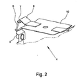
- the Fig. 2 shows in detail a part of belonging to an inventive magnetic-inductive flowmeter 1 magnetic field generating device 4.
- a magnetic coil 6 the coil core 7, which adjoins the coil core 7 magnetic connecting element 8, integrally connected to the coil core 7, and the yoke element 10.
- the two electrodes 5 are respectively provided on the narrow sides of the "inner” measuring tube 2 or on the narrow sides of the measuring section 3.
- the coil cores 7, the magnetic connecting elements 8 and / or the yoke elements 10, to eddy currents can be carried out layered, the individual layers are of course electrically isolated from each other.
- a support element 13 is provided on each longitudinal side of the measuring section 3 between the "outer” measuring tube 2 and the “inner” measuring tube 2, and that, like the Fig. 4 shows, in the area of the electrodes 5 and the magnet coils 6, a cover element 14 applied externally to the measuring tube 2 is provided.
- a magnetic-inductive flowmeter 1 For the illustrated exemplary embodiment of a magnetic-inductive flowmeter 1 according to the invention, only one yoke element 10 is provided on each longitudinal side of the "inner" measuring tube 2, that is to say on each longitudinal side of the measuring section 3, which has a substantially rectangular cross-section, on its two narrow sides each with a magnetic connection element 8 is magnetically well connected.
- the magnetic field generating device 4 then only works if the magnetic coils 6 magnetically connected via the coil cores 7 and the magnetic connecting elements 8 to the yoke element 10 produce rectified magnetic fields.
- the north poles of the individual magnetic coils are each marked with an "N", the south poles each with an "S".
- magnetic-inductive flowmeters 1 with only one yoke element 10 on one longitudinal side of the measuring section 3 and only one further yoke element 10 on the other longitudinal side of the measuring section 3 is readily possible, it is also possible to have two yoke elements 10 on each longitudinal side of the measuring section 3 provide. In this case, the two yoke elements 10 provided on one side of the measuring section 3 are then separated by a gap.
- the magnetic coils 6 and in particular their turns are made flat to keep the space occupied by the magnetic coils 6 as small as possible.
- the yoke elements 10 are substantially wider than the magnetic connecting elements 8 and the coil cores 7 executed.
- the functional magnetic field is "extended" in the flow direction of the measuring fluid.
Landscapes
- Physics & Mathematics (AREA)
- Electromagnetism (AREA)
- Fluid Mechanics (AREA)
- General Physics & Mathematics (AREA)
- Measuring Volume Flow (AREA)
Abstract
Description
- Die Erfindung betrifft ein magnetisch-induktives Durchflussmessgerät mit mindestens einem Messrohr, wobei das Messrohr mindestens einen Messabschnitt aufweist, mit mindestens einer Magnetfelderzeugungseinrichtung zum Erzeugen eines Magnetfeldes im Messabschnitt des Messrohres, und mit wenigstens zwei im Messabschnitt des Messrohres angeordneten Elektroden zur Erfassung einer Messspannung, wobei die Magnetfelderzeugungseinrichtung mindestens eine vorzugsweise außerhalb des Messabschnitts des Messrohres angeordnete Magnetspule mit einem Spulenkern aufweist.
- Für die Durchflussmessung mit einem magnetisch-induktiven Durchflussmessgerät wird ein Messrohr vorzugsweise aus einem nichtmagnetischen Werkstoff, beispielsweise aus Kunststoff oder einem nichtmagnetischen Metall verwendet, das im Bereich eines Messabschnitts von dem Messmedium bzw. dem Messfluid - z. B. einer Flüssigkeit, einem Gas oder einer Mischung aus einer Flüssigkeit und darin befindlichen Feststoffen - elektrisch von dem Messfluid isoliert ist. Gemäß dem Stand der Technik durchsetzt im Betrieb ein von einer Magnetfelderzeugungseinrichtung erzeugtes Magnetfeld das Messrohr im Messabschnitt zumindest teilweise im Wesentlichen senkrecht zur Strömungsrichtung des Messmediums. Weist das Messmedium eine elektrische Mindestleitfähigkeit auf, so werden während des Strömens des Mediums dessen Ladungsträger durch das Magnetfeld abgelenkt. An senkrecht zum Magnetfeld und zur Strömungsrichtung angeordneten Elektroden, die entweder galvanisch oder kapazitiv mit dem Messmedium gekoppelt sind, entsteht durch die Ladungstrennung eine elektrische Potentialdifferenz, die mit einem Messgerät erfasst und als Messspannung ausgewertet wird. Da die abgreifbare Messspannung proportional zur Strömungsgeschwindigkeit der mit dem Messmedium bewegten Ladungsträger ist, kann aus der abgreifbaren Messspannung auf die Strömungsgeschwindigkeit und aus der Strömungsgeschwindigkeit dann auf den Durchfluss im Messrohr geschlossen werden.
- Die Magnetfelderzeugungseinrichtung besteht im Stand der Technik zumeist aus mindestens einer Magnetspule mit einem Spulenkern und aus zwei einander diametral gegenüberliegenden Polschuhen, von denen wenigstens einer magnetisch leitend mit der Magnetspule bzw. dem Spulenkern der Magnetspule verbunden ist. Dabei wird durch die Bestromung der Magnetspule bzw. der Magnetspulen in der Regel ein alternierendes Magnetfeld im Messabschnitt des Messrohres erzeugt.
- Die Höhe der an den Elektroden abgreifbaren Messspannung ist insbesondere abhängig von der Feldstärke des einwirkenden Magnetfeldes. Daher werden im Stand der Technik Maßnahmen getroffen, um die Feldstärke des einwirkenden Magnetfeldes, aber auch um die Homogenität des einwirkenden Magnetfeldes zu erhöhen.
- Das magnetisch-induktive Durchflussmessgerät, von dem die Erfindung ausgeht, ist aus einer deutschen Offenlegungsschrift bekannt, nämlich aus der
DE 10 2006 060 442 A1 . Bei diesem bekannten magnetisch-induktiven Durchflussmessgerät ist die Magnetfelderzeugungseinrichtung zweiteilig ausgeführt; sie besteht nämlich aus zwei ineinander steckbaren Modulen, die jeweils über eine Magnetspule verfügen, Die Module werden für die Messung klemmend an die Außenwand des Messrohres angebracht, und das Messrohr weist in dem von den Modulen umfassten Messabschnitt eine abgeflachte Form auf. Die gesamte Magnetfelderzeugungseinrichtung befindet sich also bei dem bekannten magnetisch-induktiven Durchflussmessgerät, von dem die Erfindung ausgeht, außerhalb des Messrohres. - Für die Ausgestaltung von magnetisch-induktiven Durchflussmessgeräten sind im Allgemeinen zwei unterschiedliche Bedingungen zu erfüllen bzw. geht das Streben dahin, entsprechende Optimierungen zu erzielen. Zum einen ist dies die Erhöhung der Messgenauigkeit, wozu das obige Vorgehen zur Erhöhung der Feldstärke des Magnetfelds oder auch die Optimierung der Form des Magnetfeldes innerhalb des Messabschnitts gehören. Zum anderen ist dies die äußere Dimensionierung des Durchflussmessgeräts. Da Durchflussmessgeräte in Prozessanlagen zur Anwendung kommen, bei denen häufig Platzmangel herrscht, ist es vorteilhaft, wenn das Durchflussmessgerät selbst möglichst klein bzw. kompakt ist.
- Der Erfindung liegt die Aufgabe zugrunde, ein magnetisch-induktives Durchflussmessgerät anzugeben, bei dem konstruktiv die Messgenauigkeit unterstützt wird und das sich durch einen möglichst geringen Bauraum auszeichnet.
- Das erfindungsgemäße magnetisch-induktive Durchflussmessgerät, bei dem die zuvor hergeleitete und aufgezeigte Aufgabe gelöst ist, ist zunächst und im Wesentlichen dadurch gekennzeichnet, dass der Spulenkern der Magnetspule bzw. die Spulenkerne der Magnetspulen in Bezug auf den magnetischen Fluss mit mindestens zwei Jochelementen bzw. die Spulenkerne der Magnetspulen mit mindestens jeweils einem Jochelement kontaktiert ist bzw. sind und dass die Jochelemente zumindest teilweise den Messabschnitt des Messrohres begrenzen. Das "Begrenzen des Messabschnitts des Messrohres" kann insbesondere bedeuten, dass der Messabschnitt des Messrohres zumindest teilweise durch die mit dem Spulenkern der Magnetspule bzw. den Spulenkernen der Magnetspulen magnetisch leitend verbundenen Jochelemente gebildet ist.
- Während bei dem magnetisch-induktiven Durchflussmessgerät, das durch die
DE 10 2006 060 442 A1 bekannt ist und von dem die Erfindung ausgeht, die gesamte Magnetfelderzeugungseinrichtung außerhalb des Messrohres, und zwar außerhalb des Messabschnitts des Messrohres realisiert ist, können bei dem erfindungsgemäßen magnetisch-induktiven Durchflussmessgerät die mit dem Spulenkern der Magnetspule bzw. die mit den Spulenkernen der Magnetspulen in Bezug auf den magnetischen Fluss kontaktierten Jochelemente zumindest teilweise den Messabschnitt des Messrohres bilden. - Der Erläuterung bedarf, was im Rahmen der Erfindung mit "Messrohr" und mit "Messabschnitt des Messrohres" gemeint sein soll.
- Mit "Messrohr" ist das Bauteil des in Rede stehenden magnetisch-induktiven Durchflussmessgeräts gemeint, durch das - von einem Messrohreintritt bis zu einem Messrohraustritt - das Messfluid strömt, dessen Durchfluss gemessen werden soll. Der "Messabschnitt des Messrohres" ist ein Abschnitt des Messrohres, der - in Strömungsrichtung des strömenden Messfluids gesehen-hinter dem Messrohreintritt und vor dem Messrohraustritt liegt und in dem die Durchflussmessung erfolgt, dass heißt das erzeugte Magnetfeld auf das strömende Messfluid einwirkt und dadurch im strömenden Messfluid die Ladungstrennung erfolgt und daraus eine elektrische Potentialdifferenz entsteht, die als Messspannung abgegriffen und ausgewertet werden kann.
- Der "Messabschnitt des Messrohres" kann ganz einfach ein Abschnitt des Messrohres sein, wie zuvor räumlich und funktional erläutert. Der "Messabschnitt des Messrohres" kann aber auch ein geometrisch-räumlich besonders gestalteter Abschnitt des Messrohres sein. Insbesondere kann der "Messabschnitt des Messrohres" dadurch gebildet sein, dass das Messrohr im Bereich des Messabschnitts beidseitig abgeflacht ist, der "Messabschnitt des Messrohres" also ein Rechteck oder ein Rechteck mit abgerundeten Ecken sein kann.
- Nicht selten sind bei magnetisch-induktiven Durchflussmessgeräten die Magnetspulen nicht in der Nähe bzw. im Bereich der Elektroden vorgesehen, sondern um 90° gegenüber den Elektroden versetzt. Bei dem erfindungsgemäßen magnetisch-induktiven Durchflussmessgerät bietet es sich jedoch an, die Magnetspulen in der Nähe der Elektroden anzuordnen.
- Wie schon ausgeführt, kann bei dem erfindungsgemäßen magnetisch-induktiven Durchflussmessgeräts der Messabschnitts des Messrohres, also das "innere" Messrohr, einen im Wesentlichen rechteckigen Querschnitt haben, also zwei Längsseiten und zwei Schmalseiten bzw. Querseiten aufweisen.
- Bei der zuletzt beschriebenen Ausführungsform eines erfindungsgemäßen magnetisch-induktiven Durchflussmessgeräts kann die Magnetspule bzw. können die Magnetspulen innerhalb des Messrohres, und zwar innerhalb des "äußeren" Messrohres, natürlich aber außerhalb des "inneren" Messrohres angeordnet sein. Gleichwohl empfiehlt es sich, die Magnetspule bzw. die Magnetspulen außerhalb des Messrohres, und zwar außerhalb des "äußeren" Messrohres anzuordnen, weil dann anfänglich die Montage besonders einfach und eine zum Beispiel reparaturbedingte Demontage besonders einfach ausgeführt werden kann.
- Wie bereits ausgeführt, erfordert in der Regel ein magnetisch-induktives Durchflussmessgerät einer bestimmten Größe auch ein Magnetfeld mit einer bestimmten Feldstärke. Die Feldstärke ergibt sich einerseits aus der Größe der Magnetspule bzw. der Magnetspulen, andererseits aus der Bestromung. Unter Berücksichtigung der Tatsache, dass ein geringer Bauraum angestrebt wird, kann es empfehlenswert sein, die Magnetfelderzeugungseinrichtung mit insgesamt vier Magnetspulen zu versehen.
- Nachfolgend wird eine besonders bevorzugte Ausführungsform eines erfindungsgemäßen magnetisch-induktiven Durchflussmessgeräts beschrieben. Diese besondere Ausführungsform ist zunächst und im Wesentlichen zusätzlich zu bisher beschriebenen Maßnahmen dadurch gekennzeichnet, dass zwischen dem Spulenkern der Magnetspule bzw. zwischen jedem Spulenkern jeder Magnetspule jeweils ein magnetisches Verbindungselement vorgesehen ist. Dann empfiehlt es sich, das Messrohr mit einer Ausnehmung bzw. mit Ausnehmungen zu versehen und das magnetische Verbindungselement bzw. die magnetischen Verbindungselemente durch die Ausnehmung bzw. durch die Ausnehmungen hindurchzuführen.
- Was mit den zuletzt beschriebenen Maßnahmen erreichbar ist und welche Vorteile die Realisierung dieser Maßnahmen bringt und inwiefern bei dem erfindungsgemäßen magnetisch-induktiven Durchflussmessgerät weitere Maßnahmen vorteilhafterweise realisiert werden können, wird noch erläutert. Im Einzelnen gibt es nämlich eine Vielzahl von Möglichkeiten, das erfindungsgemäße magnetisch-induktive Durchflussmessgerät auszugestalten und weiterzubilden. Dazu wird verwiesen auf die dem Patentanspruch 1 nachgeordneten Patentansprüche sowie auf die Beschreibung von bevorzugten Ausführungsbeispielen in Verbindung mit der Zeichnung. In der Zeichnung zeigen
- Fig. 1
- einen Schnitt durch ein magnetisch-induktives Durchflussmessgerät, schematisch dargestellt, mit einem vergrößerten Detail,
- Fig. 2
- in einer räumlichen Darstellung, ein Detail einer zu einem erfindungsgemäßen magnetisch-induktiven Durchflussmessgerät gehörenden Magnetfelderzeugungseinrichtung,
- Fig. 3
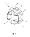
- in einer räumlichen Darstellung, einen Teil eines erfindungsgemäßen magnetisch-induktiven Durchflussmessgeräts und
- Fig. 4
- in einer räumlichen Darstellung, sehr schematisch, ein magnetischinduktives Durchflussmessgerät.
- Die
Fig. 1 zeigt, schematisch dargestellt, einen Schnitt durch ein magnetisch-induktives Durchflussmessgerät 1 mit einem zylindrischen, einen kreisförmigen Querschnitt aufweisenden Messrohr 2. Ein Teil des Messrohres 2, in Strömungsrichtung des Messfluids gesehen, üblicherweise in der Mitte des Messrohres 2, jedenfalls im mittleren Bereich des Messrohres 2, ist ein Messabschnitt 3 realisiert. Der Messabschnitt 3 hat im dargestellten Ausführungsbeispiel im Wesentlichen einen rechteckigen Querschnitt, wobei die kurzen Seiten nicht grade sind, vielmehr, als Teil des Messrohres 2 mit kreisförmigem Querschnitt, kreisbogenförmig ausgeführt sind. - Im dargestellten Ausführungsbeispiel ist das Messrohr 2 einerseits geometrisch-räumlich, andererseits funktional zu betrachten. Geometrisch-räumlich betrachtet hat das Messrohr 2, beginnend mit dem Messrohreintritt und endend mit dem Messrohraustritt, durchgehend einen kreisförmigen Querschnitt. Funktional betrachtet weist das Messrohr 2 jedoch eine im Messabschnitt 3 realisierende Querschnittsverengung auf. Diese Querschnittsverengung führt zu einer Erhöhung der Geschwindigkeit des strömenden Messfluids und damit zu einer Erhöhung der Messspannung bei im Übrigen gleichen Verhältnissen.
- Zu dem - in den Figuren nur schematisch dargestellten - magnetisch-induktiven Durchflussmessgerät gehört funktionsnotwendig eine Magnetfelderzeugungseinrichtung 4, die ein periodisch wechselndes Magnetfeld erzeugt. An den kurzen Seiten des im Wesentlichen rechteckigen Messabschnitts 3 des Messrohres 2 sind zwei Elektroden 5 angebracht, die im direkten Kontakt mit dem - nicht dargestellten - Messfluid stehen und die dem Abgriff einer induzierten Spannung dienen.
- Die Magnetfelderzeugungseinrichtung 4 weist vier Magnetspulen 6 auf, deren Spulenkerne 7 in magnetische Verbindungselemente 8 übergehen; die Spulenkerne 7 und die magnetischen Verbindungselemente 8 sind also im dargestellten Ausführungsbeispiel Bauteile der Magnetfelderzeugungseinrichtung 4, die einerseits, innerhalb der Magnetspulen 6, die Spulenkerne 7, und andererseits die magnetischen Verbindungselemente 8 realisieren. Dabei weisen sowohl die Spulenkerne 7 als auch die magnetischen Verbindungselemente 8 bzw., im dargestellten Ausführungsbeispiel, die die Spulenkerne 7 und die magnetischen Verbindungselemente 8 realisierenden Bauteile eine hohe magnetische Permeabilität auf. Denkbar sind aber auch Ausführungsformen, bei denen die Spulenkerne 7 einerseits und die ersten Jochelemente andererseits zunächst getrennte Bauteile sind, die dann miteinander verbunden werden, und zwar so miteinander verbunden werden, dass sie funktional wie ein Bauteil wirken, insbesondere also insgesamt eine hohe magnetische Permeabilität verwirklicht ist. Bei getrennter Ausführung der Spulenkerne 7 und der magnetischen Verbindungselemente 8 müssen also die Spulenkerne 7 und die magnetischen Verbindungselemente 8 so miteinander verbunden sein, dass zwischen ihnen ein möglichst geringer magnetischer Widerstand besteht.
- Dass auch im Bereich des Messabschnitts 3 geometrisch-räumlich durchgehend zylindrisch mit kreisförmigem Querschnitt ausgeführte Messrohr 2 weist vier Ausnehmungen 9 auf, durch die, wie die
Fig. 1 zeigt, die magnetischen Verbindungselemente 8 in das Innere des "äußeren" Messrohres 2 hineinragen. - Wie ausgeführt, ist das Messrohr 2 auch im Bereich des Messabschnitts 3 zunächst geometrisch-räumlich genau so ausgeführt, wie außerhalb des Messabschnitts 3. Im Übrigen ist aber das Messrohr 2 im Bereich des Messabschnitts 3 funktional so ausgeführt, wie weiter oben beschrieben, nämlich mit einer Querschnittsverengung, so dass das Messrohr 2 im Bereich des Messabschnitts 3 auch einen Teil mit einem rechteckigen Querschnitt hat. Im Bereich des Messabschnitts 3 gibt es also gleichsam ein "äußeres" Messrohr 2, zylindrisch, mit einem kreisförmigen Querschnitt, und ein "inneres" Messrohr 2 mit einem rechteckigen Querschnitt, wobei im Bereich des "inneren" Messrohres 2 der Messabschnitt 3 realisiert ist.
- Wie die
Fig. 1 und2 im Einzelnen zeigen, ansatzweise auch dieFig. 3 zeigt, sind die Spulenkerne 7 der Magnetspulen 6 in Bezug auf den magnetischen Fluss mit Jochelementen 10 verbunden, und zwar mit Jochelementen 10, die, wie die Spulenkerne 7, eine hohe magnetische Permeabilität aufweisen. Da im dargestellten Ausführungsbeispiel sich an die Spulenkerne 7 der Magnetspulen 6 zunächst magnetische Verbindungselemente 8 anschließen, sind im Ausführungsbeispiel die Jochelemente 10 mit den magnetischen Verbindungselementen 8 "magnetisch" verbunden, das heißt im Übergang zwischen den magnetischen Verbindungselementen und den Jochelementen ist wiederum ein möglichst geringer magnetischer Widerstand verwirklicht. - Wie die
Fig. 1 und3 zeigen, begrenzen die Jochelemente 10 den Messabschnitt 3 des Messrohres 2. Das Begrenzen des Messabschnitts 3 des Messrohres 2 kann bedeuten, dass der Messabschnitt 3 des Messrohres 2 teilweise durch die - über die magnetischen Verbindungselemente 8 - mit den Spulenkernen 7 der Magnetspulen magnetisch leitend verbundenen Jochelemente 10 gebildet ist. Bei dieser Ausführungsform sind also die Jochelemente 10 ein Teil des im Bereich des Messabschnitts 3 verwirklichten "inneren" Messrohres 2. Im dargestellten Ausführungsbeispiel ist jedoch das "innere" Messrohr 2 durchgehend vorhanden, es ist also nicht, was durchaus vorteilhaft realisiert sein kann, teilweise durch die Jochelemente 10 gebildet. Im Bereich der Längsseiten des "inneren" Messrohres 2 bildet das "innere" Messrohr 2 Trägerelemente 11 für die Jochelemente 10. - Im dargestellten Ausführungsbeispiel eines erfindungsgemäßen magnetischinduktiven Durchflussmessgeräts ist das Messrohr 2, und zwar sowohl das "äußere" Messrohr 2 als auch das "innere" Messrohr 2 (im Bereich des Messabschnitts 3) mit einer Innenauskleidung 12 versehen die Schutz gegenüber einem Messfluid gewährt, das aggressiv oder abrasiv sein kann.
- Das vergrößerte Detail in der
Fig. 1 lässt gut erkennen, dass im Ausführungsbeispiel das Messrohr 2 mit Ausnehmungen 9 versehen ist, konkret ist natürlich nur eine Ausnehmung 9 zu sehen, dass durch die Ausnehmung 9 das magnetische Verbindungselement 8 ragt, wobei das magnetische Verbindungselement 8 entweder magnetisch gut leitend mit dem Spulenkern 7 einer Magnetspule 6 verbunden ist oder das magnetische Verbindungselement 8 und der Spulenkern 7 ein Bauteil mit hoher magnetischer Permeabilität ist. Mit dem magnetischen Verbindungselement 8 ist - magnetisch gut leitend-das Jochelement 10 verbunden, das auf dem "inneren" Messrohr 2 im Bereich des Messabschnitts 3, das "innere" Messrohr 2 dort als Trägereinheit 11 ausgebildet, aufliegt. - Im Ausführungsbeispiel, aber nicht zwingend so zu realisieren, befinden sich die Magnetspulen 6 außerhalb des Messrohres 2, und zwar sowohl außerhalb des "inneren" Messrohres 2 als auch außerhalb des "äußeren" Messrohres 2. Das für ein magnetisch-induktives Durchflussmessgerät erforderliche Magnetfeld lässt sich durch die Bestromung der Magnetspulen 6 einstellen bzw. steuern. Die Bestromung ist dabei davon abhängig, wie viele und welche Arten von Magnetspulen 6 vorgesehen sind und welche Stärke das Magnetfeld im Messabschnitt 3 haben soll.
- Wie die
Fig. 1 zeigt, sind bei dem in Rede stehenden magnetisch-induktiven Durchflussmessgerät vier Magnetspulen vorgesehen; auf jeder Schmalseite des Messabschnitts 3 sind jeweils zwei Magnetspulen 6 vorgesehen, und zwar außerhalb des "inneren" Messrohres 2 und auch außerhalb des "äußeren" Messrohres 2. Es ist jedoch auch möglich, die Magnetspulen 6 zwar außerhalb des "inneren" Messrohres 2, aber innerhalb des "äußeren" Messrohres 2 vorzusehen, weil in dem Raum zwischen dem "äußeren" Messrohr 2 und dem "inneren" Messrohr 2 das Messfluid ja nicht strömt, dies vielmehr im Bereich des Messabschnitts 3 nur innerhalb des "inneren" Messrohres 2 strömt. Die Anordnung der Magnetspulen 6 außerhalb des "äußeren" Messrohres 2 hat jedoch den Vorteil der besonders einfachen Montage und des besonders einfachen Austausches, wenn das erforderlich sein sollte. - Die
Fig. 2 zeigt noch im Detail einen Teil der zu einem erfindungsgemäßen magnetisch-induktiven Durchflussmessgerät 1 gehörenden Magnetfelderzeugungseinrichtung 4. Man sieht ohne Weiteres eine Magnetspule 6, deren Spulenkern 7, das sich an den Spulenkern 7 anschließende magnetische Verbindungselement 8, einstückig mit dem Spulenkern 7 verbunden, und das Jochelement 10. - Im Übrigen gilt für das dargestellte Ausführungsbeispiel eines erfindungsgemäßen magnetisch-induktiven Durchflussmessgeräts, dass die beiden Elektroden 5 jeweils an den Schmalseiten des "inneren" Messrohres 2 bzw. an den Schmalseiten des Messabschnitts 3 vorgesehen sind.
- Im Einzelnen nicht dargestellt ist, dass die Spulenkerne 7, die magnetischen Verbindungselemente 8 oder / und die Jochelemente 10, um Wirbelströme möglichst gering zu halten bzw. zu vermeiden, geschichtet ausgeführt sein können, die einzelnen Schichten natürlich elektrisch gegeneinander isoliert sind.
- Für das dargestellte Ausführungsbeispiel eines erfindungsgemäßen magnetisch-induktiven Durchflussmessgeräts 1 gilt weiter, dass auf jeder Längsseite des Messabschnitts 3 zwischen dem "äußeren" Messrohr 2 und dem "inneren" Messrohr 2 ein Abstützelement 13 vorgesehen ist, und dass, wie die
Fig. 4 zeigt, im Bereich der Elektroden 5 und der Magnetspulen 6 ein von Außen auf das Messrohr 2 aufgebrachtes Abdeckelement 14 vorgesehen ist. - Für das dargestellte Ausführungsbeispiel eines erfindungsgemäßen magnetisch-induktiven Durchflussmessgeräts 1 gilt, dass auf jeder Längsseite des "inneren" Messrohres 2, also auf jeder Längsseite des im Wesentlichen mit rechteckigem Querschnitt ausgeführten Messabschnitts 3, nur ein Jochelement 10 vorgesehen ist, das an seinen beiden Schmalseiten jeweils mit einem magnetischen Verbindungselement 8 magnetisch gut leitend verbunden ist. Dabei funktioniert dann die Magnetfelderzeugungseinrichtung 4 nur dann, wenn die - über die Spulenkerne 7 und die magnetischen Verbindungselemente 8 mit dem Jochelement 10 magnetisch verbundenen Magnetspulen 6 gleichgerichtete Magnetfelder erzeugen. In der Figur sind die Nordpole der einzelnen Magnetspulen jeweils mit einem "N", die Südpole jeweils mit einem "S" gekennzeichnet.
- Ist auch eine Ausführungsform magnetisch-induktiver Durchflussmessgeräte 1 mit nur einem Jochelement 10 auf einer Längsseite des Messabschnitts 3 und nur einem weiteren Jochelement 10 auf der anderen Längsseite des Messabschnitts 3 ohne Weiteres möglich, kann man jedoch auch auf jeder Längsseite des Messabschnitts 3 zwei Jochelemente 10 vorsehen. Dabei sind dann die beiden auf einer Seite des Messabschnitts 3 vorgesehenen Jochelemente 10 durch einen Spalt getrennt.
- Der
Fig. 2 kann entnommen werden, dass im Ausführungsbeispiel die Magnetspulen 6 und insbesondere deren Windungen flach ausgeführt sind, um den Raum, der von den Magnetspulen 6 eingenommen wird, möglichst klein zu halten. - Wie wiederum insbesondere der
Fig. 2 entnommen werden kann, sind die Jochelemente 10 wesentlich breiter als die magnetischen Verbindungselemente 8 und die Spulenkerne 7 ausgeführt. Dadurch wird in Strömungsrichtung des Messfluids das funktionsnotwendige Magnetfeld "verlängert".
Claims (11)
- Magnetisch-induktives Durchflussmessgerät (1) mit mindestens einem Messrohr (2), wobei das Messrohr (2) mindestens einen Messabschnitt (3) aufweist, mit mindestens einer Magnetfelderzeugungseinrichtung (4) zum Erzeugen eines Magnetfeldes im Messabschnitts (3) des Messrohres (2), und mit wenigstens zwei im Messabschnitt (3) des Messrohres (2) angeordneten Elektroden (5) zur Erfassung einer Messspannung, wobei die Magnetfelderzeugungseinrichtung (4) mindestens eine vorzugsweise außerhalb des Messabschnitts (3) des Messrohres (2) angeordnete Magnetspule (6) mit einem Spulenkern (7) aufweist,
dadurch gekennzeichnet,
dass der Spulenkern (7) der Magnetspule (6) bzw. die Spulenkerne (7) der Magnetspulen (6) in Bezug auf den magnetischen Fluss mit mindestens zwei Jochelementen (10) bzw. die Spulenkerne (7) der Magnetspulen (6) mit mindestens jeweils zwei Jochelementen (10) kontaktiert ist bzw. sind und dass die Jochelemente (10) zumindest teilweise den Messabschnitt (3) des Messrohres (2) begrenzen. - Magnetisch-induktives Durchflussmessgerät nach Anspruch 1, dadurch gekennzeichnet, dass die Magnetspule (6) bzw. die Magnetspulen (6) in der Nähe der Elektroden (5) angeordnet ist bzw. sind.
- Magnetisch-induktives Durchflussmessgerät nach Anspruch 1 oder 2, dadurch gekennzeichnet, dass der Messabschnitt (3) des Messrohres (2) einen im Wesentlichen rechteckigen Querschnitt hat, also zwei Längsseiten und zwei Schmalseiten aufweist.
- Magnetisch-induktives Durchflussmessgerät nach Anspruch 1 bis 3, dadurch gekennzeichnet, dass die Magnetspule (6) bzw. Magnetspulen (6) außerhalb des Messrohres (2) angeordnet ist bzw. sind.
- Magnetisch-induktives Durchflussmessgerät nach einem der Ansprüche 1 bis 4, dadurch gekennzeichnet, dass die Magnetfelderzeugungseinrichtung (4) vier Magnetspulen (6) aufweist.
- Magnetisch-induktives Durchflussmessgerät nach einem der Ansprüche 1 bis 5, dadurch gekennzeichnet, dass zwischen dem Spulenkern (7) der Magnetspule (6) bzw. zwischen jedem Spulenkern (7) jeder Magnetspule (6) jeweils ein magnetisches Verbindungselement (8) vorgesehen ist.
- Magnetisch-induktives Durchflussmessgerät nach Anspruch 6, dadurch gekennzeichnet, dass das Messrohr (2) eine Ausnehmung (9) bzw. Ausnehmungen (9) aufweist und dass das magnetische Verbindungselement (8) bzw. die magnetischen Verbindungselemente (8) durch die Ausnehmung (9) bzw. die Ausnehmungen (9) hindurchgeführt ist bzw. sind.
- Magnetisch-induktives Durchflussmessgerät nach einem der Ansprüche 2 bis 7, dadurch gekennzeichnet, dass vier Jochelemente (10) vorgesehen sind, nämlich zwei Jochelemente (10) auf jeder Längsseite des Messabschnitts (3) des Messrohres (2), und dass zwischen den auf einer Längsseite des Messabschnitts (3) des Messrohres (2) vorgesehenen Jochelementen (10) ein magnetischer Spalt realisiert ist.
- Magnetisch-induktives Durchflussmessgerät nach einem der Ansprüche 1 bis 8, dadurch gekennzeichnet, dass das Messrohr (2) eine Innenauskleidung (12) aufweist.
- Magnetisch-induktives Durchflussmessgerät nach einem der Ansprüche 1 bis 9, dadurch gekennzeichnet, dass zwischen dem Messrohr (2), nämlich dem "äußeren" Messrohr (2), und dem Messabschnitt (3), nämlich der Längsseite des "inneren" Messrohres (2), jeweils ein Abstützelement (13) vorgesehen ist.
- Magnetisch-induktives Durchflussmessgerät nach einem der Ansprüche 1 bis 10, dadurch gekennzeichnet, dass auf der Außenseite des Messrohres (2) ein Abdeckelement (14) zum Abdecken der Elektroden (5), der Magnetspulen (6), der Spulenkerne (7) und teilweise der magnetischen Verbindungselemente (8) vorgesehen ist.
Applications Claiming Priority (1)
| Application Number | Priority Date | Filing Date | Title |
|---|---|---|---|
| DE102012014266.8A DE102012014266A1 (de) | 2012-07-19 | 2012-07-19 | Magnetisch-induktives Durchflussmessgerät |
Publications (3)
| Publication Number | Publication Date |
|---|---|
| EP2687827A2 true EP2687827A2 (de) | 2014-01-22 |
| EP2687827A3 EP2687827A3 (de) | 2015-07-01 |
| EP2687827B1 EP2687827B1 (de) | 2023-05-10 |
Family
ID=48874091
Family Applications (1)
| Application Number | Title | Priority Date | Filing Date |
|---|---|---|---|
| EP13003422.6A Active EP2687827B1 (de) | 2012-07-19 | 2013-07-08 | Magnetisch-induktives Durchflussmessgerät |
Country Status (4)
| Country | Link |
|---|---|
| US (1) | US9121739B2 (de) |
| EP (1) | EP2687827B1 (de) |
| CN (1) | CN103575342B (de) |
| DE (1) | DE102012014266A1 (de) |
Families Citing this family (9)
| Publication number | Priority date | Publication date | Assignee | Title |
|---|---|---|---|---|
| KR101978776B1 (ko) * | 2013-02-28 | 2019-05-16 | 삼성전자주식회사 | 다수의 안테나를 사용하는 이동통신 시스템에서 피드백 송수신 방법 및 장치 |
| US20150373744A1 (en) * | 2013-03-04 | 2015-12-24 | Nokia Technologies Oy | Synchronized physical layer reconfiguration among user equipment, macrocell, and small cell in macrocell-assisted small cell deployments |
| CA2910662C (en) * | 2013-04-26 | 2017-10-31 | Huawei Technologies Co., Ltd. | Data transmission method, base station, and wireless communications device |
| DE102014113409A1 (de) * | 2014-09-17 | 2016-03-17 | Endress+Hauser Flowtec Ag | Magnetisch-induktives Durchflussmessgerät mit einem Magnetsystem mit mindestens vier Spulen |
| DE102015116679A1 (de) * | 2015-01-14 | 2016-07-14 | Krohne Ag | Magnetisch-induktives Durchflussmessgerät |
| US9631961B2 (en) * | 2015-08-19 | 2017-04-25 | Sensus Spectrum Llc | Inductive flow meter including extended magnetic pole pieces |
| DE102019123528B4 (de) | 2019-09-03 | 2024-05-08 | Krohne Ag | Magnetisch-induktives Durchflussmessgerät und Magnetkreisvorrichtung |
| CN111307027B (zh) * | 2020-02-28 | 2021-10-29 | 北京纳米能源与系统研究所 | 机电一体式自供能位置传感装置及流体流量传感器 |
| JP2024002967A (ja) * | 2022-06-23 | 2024-01-11 | クローネ アクチェンゲゼルシャフト | 磁気誘導式流量測定装置 |
Citations (1)
| Publication number | Priority date | Publication date | Assignee | Title |
|---|---|---|---|---|
| DE102006060442A1 (de) | 2006-12-19 | 2008-06-26 | Endress + Hauser Flowtec Ag | Vorrichtung zum Messen des Volumen- oder Massestroms eines Mediums in einer Rohrleitung |
Family Cites Families (21)
| Publication number | Priority date | Publication date | Assignee | Title |
|---|---|---|---|---|
| US4409846A (en) * | 1979-02-08 | 1983-10-18 | Aichi Tokei Denki Co., Ltd. | Electromagnetic flow meter |
| DE3031997C2 (de) * | 1980-08-25 | 1986-01-16 | Licentia Patent-Verwaltungs-Gmbh, 6000 Frankfurt | Anordnung zur berührungslosen Messung statischer und dynamischer Drehmomente |
| JPS57200821A (en) * | 1981-06-05 | 1982-12-09 | Aichi Tokei Denki Co Ltd | Electromagnetic flow meter |
| US4470309A (en) * | 1981-07-06 | 1984-09-11 | Tokyo Shibaura Denki Kabushiki Kaisha | Electromagnetic flowmeter |
| DE3401377C2 (de) * | 1984-01-17 | 1986-11-13 | Danfoss A/S, Nordborg | Elektromagnetischer Durchflußmesser |
| JPH0713584B2 (ja) * | 1986-01-31 | 1995-02-15 | 愛知時計電機株式会社 | 残留磁気型電磁流量計を用いた熱量計 |
| JPS62188910A (ja) * | 1986-02-14 | 1987-08-18 | Aichi Tokei Denki Co Ltd | 電磁流量計 |
| DE3870125D1 (de) * | 1987-10-01 | 1992-05-21 | Flowtec Ag | Magnetisch-induktive durchflussmessanordnung. |
| EP0649005B1 (de) * | 1993-10-14 | 1997-04-23 | Endress + Hauser Flowtec AG | Magnetisch-induktive Durchflussaufnehmer |
| JP4303039B2 (ja) * | 2002-09-25 | 2009-07-29 | 株式会社東芝 | 容量式電磁流量計 |
| JP2004233203A (ja) * | 2003-01-30 | 2004-08-19 | Yamatake Corp | 電磁流量計用測定管 |
| US6983661B2 (en) * | 2003-05-15 | 2006-01-10 | Endress + Hauser Flowtec Ag | Electromagnetic flow sensor |
| WO2005124292A1 (de) * | 2004-06-16 | 2005-12-29 | Endress + Hauser Flowtec Ag | Magnetisch-induktiver durchflussaufnehmer |
| GB2440964B (en) * | 2006-08-18 | 2011-08-10 | Abb Ltd | Flow meter |
| DE102007032879A1 (de) | 2007-07-12 | 2009-01-15 | Endress + Hauser Flowtec Ag | Vorrichtung zum Messen des Volumen- oder Massestroms eines mediums in einer Rohrleitung |
| JP4721073B2 (ja) * | 2008-04-18 | 2011-07-13 | Smc株式会社 | 電磁流量計 |
| DE102008035740A1 (de) * | 2008-07-31 | 2010-02-04 | Abb Technology Ag | Magnetisch induktiver Durchflussmesser mit einer kombinierte magnetische Flussleitmittel umfassenden Elektromagenteinheit |
| DE102008057755B4 (de) | 2008-11-17 | 2015-12-17 | Krohne Ag | Magnetisch-induktives Durchflußmeßgerät |
| DE102008057756A1 (de) | 2008-11-17 | 2010-05-27 | Krohne Ag | Magnetisch-induktives Durchflußmeßgerät |
| BRPI1104663A2 (pt) * | 2010-09-06 | 2013-01-15 | Mr Technologies S A | medidor de precisço para fluxos reduzidos |
| DE102012017904A1 (de) * | 2012-08-21 | 2014-03-20 | Krohne Ag | Magnetisch-induktives Durchflussmessgerät und Verfahren zu seiner Herstellung |
-
2012
- 2012-07-19 DE DE102012014266.8A patent/DE102012014266A1/de active Pending
-
2013
- 2013-07-08 EP EP13003422.6A patent/EP2687827B1/de active Active
- 2013-07-19 CN CN201310304279.8A patent/CN103575342B/zh active Active
- 2013-07-19 US US13/946,164 patent/US9121739B2/en active Active
Patent Citations (1)
| Publication number | Priority date | Publication date | Assignee | Title |
|---|---|---|---|---|
| DE102006060442A1 (de) | 2006-12-19 | 2008-06-26 | Endress + Hauser Flowtec Ag | Vorrichtung zum Messen des Volumen- oder Massestroms eines Mediums in einer Rohrleitung |
Also Published As
| Publication number | Publication date |
|---|---|
| EP2687827A3 (de) | 2015-07-01 |
| CN103575342B (zh) | 2020-08-14 |
| CN103575342A (zh) | 2014-02-12 |
| US9121739B2 (en) | 2015-09-01 |
| DE102012014266A1 (de) | 2014-01-23 |
| US20140020477A1 (en) | 2014-01-23 |
| EP2687827B1 (de) | 2023-05-10 |
Similar Documents
| Publication | Publication Date | Title |
|---|---|---|
| EP2687827B1 (de) | Magnetisch-induktives Durchflussmessgerät | |
| EP2440886B1 (de) | Magnetisch-induktiver durchflussmesser | |
| DE102012221616B4 (de) | Magnetisch induktiver Durchflussmesser | |
| DE102011119982A1 (de) | Magnetisch-induktives Durchflussmessgerät | |
| DE102014104107A9 (de) | Elektromagnetischer Strömungsmesser | |
| EP2761257A1 (de) | Magnetisch-induktives durchflussmessgerät | |
| DE102011079352A1 (de) | Magnetisch-induktives Durchflussmessgerät | |
| DE102015116679A1 (de) | Magnetisch-induktives Durchflussmessgerät | |
| DE102012017904A1 (de) | Magnetisch-induktives Durchflussmessgerät und Verfahren zu seiner Herstellung | |
| DE102014113408A1 (de) | Verfahren zur Herstellung eines Magnetisch-induktives Durchfluss- messgeräts mit zum Teil reduziertem Querschnitt | |
| EP2844958B1 (de) | Magnetisch-induktives durchflussmessgerät | |
| EP3211384B1 (de) | Magnetisch-induktives durchflussmessgerät und verfahren dafür | |
| EP2761256B1 (de) | Spulensystem eines magnetisch-induktiven durchflussmessgeräts | |
| DE202009017274U1 (de) | Magnetisch-induktiver Durchflussmesser | |
| DE102005028572B4 (de) | Stromsensoranordung mit einem Magnetkern | |
| DE102009001413A1 (de) | Spulenanordnung für ein magnetisch induktives Durchflussmessgerät | |
| DE102014113409A1 (de) | Magnetisch-induktives Durchflussmessgerät mit einem Magnetsystem mit mindestens vier Spulen | |
| EP0179285B2 (de) | Magnetisch-induktiver Durchflussmesser | |
| DE102004063020B4 (de) | Magnetisch-induktives Durchflußmeßgerät | |
| DE102015122664B4 (de) | Magnetisch-induktives Durchflussmessgerät | |
| DE3435910A1 (de) | Magnetisch-induktiver durchflussmesser mit auswechselbaren durchflusssensoren | |
| EP2400274B1 (de) | Fluidstrommesseinrichtung, Ventileinrichtung und Messverfahren | |
| EP3058318A1 (de) | Messrohr für magnetisch-induktive durchflussmesssysteme | |
| EP3045875B1 (de) | Magnetisch-induktives durchflussmessgerät | |
| DE102014216535A1 (de) | Magnetisch-induktives Durchflussmessgerät |
Legal Events
| Date | Code | Title | Description |
|---|---|---|---|
| PUAI | Public reference made under article 153(3) epc to a published international application that has entered the european phase |
Free format text: ORIGINAL CODE: 0009012 |
|
| AK | Designated contracting states |
Kind code of ref document: A2 Designated state(s): AL AT BE BG CH CY CZ DE DK EE ES FI FR GB GR HR HU IE IS IT LI LT LU LV MC MK MT NL NO PL PT RO RS SE SI SK SM TR |
|
| AX | Request for extension of the european patent |
Extension state: BA ME |
|
| PUAL | Search report despatched |
Free format text: ORIGINAL CODE: 0009013 |
|
| AK | Designated contracting states |
Kind code of ref document: A3 Designated state(s): AL AT BE BG CH CY CZ DE DK EE ES FI FR GB GR HR HU IE IS IT LI LT LU LV MC MK MT NL NO PL PT RO RS SE SI SK SM TR |
|
| AX | Request for extension of the european patent |
Extension state: BA ME |
|
| RIC1 | Information provided on ipc code assigned before grant |
Ipc: G01F 1/56 20060101AFI20150526BHEP Ipc: G01F 1/58 20060101ALI20150526BHEP |
|
| 17P | Request for examination filed |
Effective date: 20160104 |
|
| RBV | Designated contracting states (corrected) |
Designated state(s): AL AT BE BG CH CY CZ DE DK EE ES FI FR GB GR HR HU IE IS IT LI LT LU LV MC MK MT NL NO PL PT RO RS SE SI SK SM TR |
|
| STAA | Information on the status of an ep patent application or granted ep patent |
Free format text: STATUS: EXAMINATION IS IN PROGRESS |
|
| 17Q | First examination report despatched |
Effective date: 20171027 |
|
| GRAP | Despatch of communication of intention to grant a patent |
Free format text: ORIGINAL CODE: EPIDOSNIGR1 |
|
| STAA | Information on the status of an ep patent application or granted ep patent |
Free format text: STATUS: GRANT OF PATENT IS INTENDED |
|
| GRAS | Grant fee paid |
Free format text: ORIGINAL CODE: EPIDOSNIGR3 |
|
| INTG | Intention to grant announced |
Effective date: 20221124 |
|
| GRAA | (expected) grant |
Free format text: ORIGINAL CODE: 0009210 |
|
| STAA | Information on the status of an ep patent application or granted ep patent |
Free format text: STATUS: THE PATENT HAS BEEN GRANTED |
|
| AK | Designated contracting states |
Kind code of ref document: B1 Designated state(s): AL AT BE BG CH CY CZ DE DK EE ES FI FR GB GR HR HU IE IS IT LI LT LU LV MC MK MT NL NO PL PT RO RS SE SI SK SM TR |
|
| REG | Reference to a national code |
Ref country code: GB Ref legal event code: FG4D Free format text: NOT ENGLISH |
|
| REG | Reference to a national code |
Ref country code: AT Ref legal event code: REF Ref document number: 1567092 Country of ref document: AT Kind code of ref document: T Effective date: 20230515 Ref country code: CH Ref legal event code: EP |
|
| REG | Reference to a national code |
Ref country code: DE Ref legal event code: R096 Ref document number: 502013016373 Country of ref document: DE |
|
| REG | Reference to a national code |
Ref country code: IE Ref legal event code: FG4D Free format text: LANGUAGE OF EP DOCUMENT: GERMAN |
|
| P01 | Opt-out of the competence of the unified patent court (upc) registered |
Effective date: 20230607 |
|
| REG | Reference to a national code |
Ref country code: NL Ref legal event code: FP |
|
| REG | Reference to a national code |
Ref country code: LT Ref legal event code: MG9D |
|
| PG25 | Lapsed in a contracting state [announced via postgrant information from national office to epo] |
Ref country code: SE Free format text: LAPSE BECAUSE OF FAILURE TO SUBMIT A TRANSLATION OF THE DESCRIPTION OR TO PAY THE FEE WITHIN THE PRESCRIBED TIME-LIMIT Effective date: 20230510 Ref country code: PT Free format text: LAPSE BECAUSE OF FAILURE TO SUBMIT A TRANSLATION OF THE DESCRIPTION OR TO PAY THE FEE WITHIN THE PRESCRIBED TIME-LIMIT Effective date: 20230911 Ref country code: NO Free format text: LAPSE BECAUSE OF FAILURE TO SUBMIT A TRANSLATION OF THE DESCRIPTION OR TO PAY THE FEE WITHIN THE PRESCRIBED TIME-LIMIT Effective date: 20230810 Ref country code: ES Free format text: LAPSE BECAUSE OF FAILURE TO SUBMIT A TRANSLATION OF THE DESCRIPTION OR TO PAY THE FEE WITHIN THE PRESCRIBED TIME-LIMIT Effective date: 20230510 |
|
| PG25 | Lapsed in a contracting state [announced via postgrant information from national office to epo] |
Ref country code: RS Free format text: LAPSE BECAUSE OF FAILURE TO SUBMIT A TRANSLATION OF THE DESCRIPTION OR TO PAY THE FEE WITHIN THE PRESCRIBED TIME-LIMIT Effective date: 20230510 Ref country code: PL Free format text: LAPSE BECAUSE OF FAILURE TO SUBMIT A TRANSLATION OF THE DESCRIPTION OR TO PAY THE FEE WITHIN THE PRESCRIBED TIME-LIMIT Effective date: 20230510 Ref country code: LV Free format text: LAPSE BECAUSE OF FAILURE TO SUBMIT A TRANSLATION OF THE DESCRIPTION OR TO PAY THE FEE WITHIN THE PRESCRIBED TIME-LIMIT Effective date: 20230510 Ref country code: LT Free format text: LAPSE BECAUSE OF FAILURE TO SUBMIT A TRANSLATION OF THE DESCRIPTION OR TO PAY THE FEE WITHIN THE PRESCRIBED TIME-LIMIT Effective date: 20230510 Ref country code: IS Free format text: LAPSE BECAUSE OF FAILURE TO SUBMIT A TRANSLATION OF THE DESCRIPTION OR TO PAY THE FEE WITHIN THE PRESCRIBED TIME-LIMIT Effective date: 20230910 Ref country code: HR Free format text: LAPSE BECAUSE OF FAILURE TO SUBMIT A TRANSLATION OF THE DESCRIPTION OR TO PAY THE FEE WITHIN THE PRESCRIBED TIME-LIMIT Effective date: 20230510 Ref country code: GR Free format text: LAPSE BECAUSE OF FAILURE TO SUBMIT A TRANSLATION OF THE DESCRIPTION OR TO PAY THE FEE WITHIN THE PRESCRIBED TIME-LIMIT Effective date: 20230811 |
|
| PG25 | Lapsed in a contracting state [announced via postgrant information from national office to epo] |
Ref country code: FI Free format text: LAPSE BECAUSE OF FAILURE TO SUBMIT A TRANSLATION OF THE DESCRIPTION OR TO PAY THE FEE WITHIN THE PRESCRIBED TIME-LIMIT Effective date: 20230510 |
|
| PG25 | Lapsed in a contracting state [announced via postgrant information from national office to epo] |
Ref country code: SK Free format text: LAPSE BECAUSE OF FAILURE TO SUBMIT A TRANSLATION OF THE DESCRIPTION OR TO PAY THE FEE WITHIN THE PRESCRIBED TIME-LIMIT Effective date: 20230510 |
|
| PG25 | Lapsed in a contracting state [announced via postgrant information from national office to epo] |
Ref country code: SM Free format text: LAPSE BECAUSE OF FAILURE TO SUBMIT A TRANSLATION OF THE DESCRIPTION OR TO PAY THE FEE WITHIN THE PRESCRIBED TIME-LIMIT Effective date: 20230510 Ref country code: SK Free format text: LAPSE BECAUSE OF FAILURE TO SUBMIT A TRANSLATION OF THE DESCRIPTION OR TO PAY THE FEE WITHIN THE PRESCRIBED TIME-LIMIT Effective date: 20230510 Ref country code: RO Free format text: LAPSE BECAUSE OF FAILURE TO SUBMIT A TRANSLATION OF THE DESCRIPTION OR TO PAY THE FEE WITHIN THE PRESCRIBED TIME-LIMIT Effective date: 20230510 Ref country code: EE Free format text: LAPSE BECAUSE OF FAILURE TO SUBMIT A TRANSLATION OF THE DESCRIPTION OR TO PAY THE FEE WITHIN THE PRESCRIBED TIME-LIMIT Effective date: 20230510 Ref country code: DK Free format text: LAPSE BECAUSE OF FAILURE TO SUBMIT A TRANSLATION OF THE DESCRIPTION OR TO PAY THE FEE WITHIN THE PRESCRIBED TIME-LIMIT Effective date: 20230510 Ref country code: CZ Free format text: LAPSE BECAUSE OF FAILURE TO SUBMIT A TRANSLATION OF THE DESCRIPTION OR TO PAY THE FEE WITHIN THE PRESCRIBED TIME-LIMIT Effective date: 20230510 |
|
| REG | Reference to a national code |
Ref country code: DE Ref legal event code: R097 Ref document number: 502013016373 Country of ref document: DE |
|
| PG25 | Lapsed in a contracting state [announced via postgrant information from national office to epo] |
Ref country code: MC Free format text: LAPSE BECAUSE OF FAILURE TO SUBMIT A TRANSLATION OF THE DESCRIPTION OR TO PAY THE FEE WITHIN THE PRESCRIBED TIME-LIMIT Effective date: 20230510 |
|
| PG25 | Lapsed in a contracting state [announced via postgrant information from national office to epo] |
Ref country code: MC Free format text: LAPSE BECAUSE OF FAILURE TO SUBMIT A TRANSLATION OF THE DESCRIPTION OR TO PAY THE FEE WITHIN THE PRESCRIBED TIME-LIMIT Effective date: 20230510 |
|
| PLBE | No opposition filed within time limit |
Free format text: ORIGINAL CODE: 0009261 |
|
| STAA | Information on the status of an ep patent application or granted ep patent |
Free format text: STATUS: NO OPPOSITION FILED WITHIN TIME LIMIT |
|
| REG | Reference to a national code |
Ref country code: BE Ref legal event code: MM Effective date: 20230731 |
|
| PG25 | Lapsed in a contracting state [announced via postgrant information from national office to epo] |
Ref country code: LU Free format text: LAPSE BECAUSE OF NON-PAYMENT OF DUE FEES Effective date: 20230708 |
|
| PG25 | Lapsed in a contracting state [announced via postgrant information from national office to epo] |
Ref country code: LU Free format text: LAPSE BECAUSE OF NON-PAYMENT OF DUE FEES Effective date: 20230708 |
|
| 26N | No opposition filed |
Effective date: 20240213 |
|
| GBPC | Gb: european patent ceased through non-payment of renewal fee |
Effective date: 20230810 |
|
| REG | Reference to a national code |
Ref country code: IE Ref legal event code: MM4A |
|
| PG25 | Lapsed in a contracting state [announced via postgrant information from national office to epo] |
Ref country code: SI Free format text: LAPSE BECAUSE OF FAILURE TO SUBMIT A TRANSLATION OF THE DESCRIPTION OR TO PAY THE FEE WITHIN THE PRESCRIBED TIME-LIMIT Effective date: 20230510 |
|
| PG25 | Lapsed in a contracting state [announced via postgrant information from national office to epo] |
Ref country code: SI Free format text: LAPSE BECAUSE OF FAILURE TO SUBMIT A TRANSLATION OF THE DESCRIPTION OR TO PAY THE FEE WITHIN THE PRESCRIBED TIME-LIMIT Effective date: 20230510 Ref country code: IT Free format text: LAPSE BECAUSE OF FAILURE TO SUBMIT A TRANSLATION OF THE DESCRIPTION OR TO PAY THE FEE WITHIN THE PRESCRIBED TIME-LIMIT Effective date: 20230510 Ref country code: BE Free format text: LAPSE BECAUSE OF NON-PAYMENT OF DUE FEES Effective date: 20230731 |
|
| PG25 | Lapsed in a contracting state [announced via postgrant information from national office to epo] |
Ref country code: IE Free format text: LAPSE BECAUSE OF NON-PAYMENT OF DUE FEES Effective date: 20230708 |
|
| PG25 | Lapsed in a contracting state [announced via postgrant information from national office to epo] |
Ref country code: GB Free format text: LAPSE BECAUSE OF NON-PAYMENT OF DUE FEES Effective date: 20230810 |
|
| PG25 | Lapsed in a contracting state [announced via postgrant information from national office to epo] |
Ref country code: IE Free format text: LAPSE BECAUSE OF NON-PAYMENT OF DUE FEES Effective date: 20230708 Ref country code: GB Free format text: LAPSE BECAUSE OF NON-PAYMENT OF DUE FEES Effective date: 20230810 |
|
| REG | Reference to a national code |
Ref country code: AT Ref legal event code: MM01 Ref document number: 1567092 Country of ref document: AT Kind code of ref document: T Effective date: 20230708 |
|
| PG25 | Lapsed in a contracting state [announced via postgrant information from national office to epo] |
Ref country code: AT Free format text: LAPSE BECAUSE OF NON-PAYMENT OF DUE FEES Effective date: 20230708 |
|
| PG25 | Lapsed in a contracting state [announced via postgrant information from national office to epo] |
Ref country code: AT Free format text: LAPSE BECAUSE OF NON-PAYMENT OF DUE FEES Effective date: 20230708 |
|
| PG25 | Lapsed in a contracting state [announced via postgrant information from national office to epo] |
Ref country code: BG Free format text: LAPSE BECAUSE OF FAILURE TO SUBMIT A TRANSLATION OF THE DESCRIPTION OR TO PAY THE FEE WITHIN THE PRESCRIBED TIME-LIMIT Effective date: 20230510 |
|
| PG25 | Lapsed in a contracting state [announced via postgrant information from national office to epo] |
Ref country code: BG Free format text: LAPSE BECAUSE OF FAILURE TO SUBMIT A TRANSLATION OF THE DESCRIPTION OR TO PAY THE FEE WITHIN THE PRESCRIBED TIME-LIMIT Effective date: 20230510 |
|
| PG25 | Lapsed in a contracting state [announced via postgrant information from national office to epo] |
Ref country code: CY Free format text: LAPSE BECAUSE OF FAILURE TO SUBMIT A TRANSLATION OF THE DESCRIPTION OR TO PAY THE FEE WITHIN THE PRESCRIBED TIME-LIMIT; INVALID AB INITIO Effective date: 20130708 |
|
| PG25 | Lapsed in a contracting state [announced via postgrant information from national office to epo] |
Ref country code: HU Free format text: LAPSE BECAUSE OF FAILURE TO SUBMIT A TRANSLATION OF THE DESCRIPTION OR TO PAY THE FEE WITHIN THE PRESCRIBED TIME-LIMIT; INVALID AB INITIO Effective date: 20130708 |
|
| PGFP | Annual fee paid to national office [announced via postgrant information from national office to epo] |
Ref country code: NL Payment date: 20250721 Year of fee payment: 13 |
|
| PGFP | Annual fee paid to national office [announced via postgrant information from national office to epo] |
Ref country code: DE Payment date: 20250917 Year of fee payment: 13 |
|
| PGFP | Annual fee paid to national office [announced via postgrant information from national office to epo] |
Ref country code: FR Payment date: 20250725 Year of fee payment: 13 |
|
| PGFP | Annual fee paid to national office [announced via postgrant information from national office to epo] |
Ref country code: CH Payment date: 20250801 Year of fee payment: 13 |
|
| PG25 | Lapsed in a contracting state [announced via postgrant information from national office to epo] |
Ref country code: TR Free format text: LAPSE BECAUSE OF FAILURE TO SUBMIT A TRANSLATION OF THE DESCRIPTION OR TO PAY THE FEE WITHIN THE PRESCRIBED TIME-LIMIT Effective date: 20230510 |