EP2687827A2 - Débitmètre à induction magnétique - Google Patents
Débitmètre à induction magnétique Download PDFInfo
- Publication number
- EP2687827A2 EP2687827A2 EP13003422.6A EP13003422A EP2687827A2 EP 2687827 A2 EP2687827 A2 EP 2687827A2 EP 13003422 A EP13003422 A EP 13003422A EP 2687827 A2 EP2687827 A2 EP 2687827A2
- Authority
- EP
- European Patent Office
- Prior art keywords
- magnetic
- measuring
- measuring tube
- coil
- section
- Prior art date
- Legal status (The legal status is an assumption and is not a legal conclusion. Google has not performed a legal analysis and makes no representation as to the accuracy of the status listed.)
- Granted
Links
Images


Classifications
-
- G—PHYSICS
- G01—MEASURING; TESTING
- G01F—MEASURING VOLUME, VOLUME FLOW, MASS FLOW OR LIQUID LEVEL; METERING BY VOLUME
- G01F1/00—Measuring the volume flow or mass flow of fluid or fluent solid material wherein the fluid passes through a meter in a continuous flow
- G01F1/56—Measuring the volume flow or mass flow of fluid or fluent solid material wherein the fluid passes through a meter in a continuous flow by using electric or magnetic effects
- G01F1/58—Measuring the volume flow or mass flow of fluid or fluent solid material wherein the fluid passes through a meter in a continuous flow by using electric or magnetic effects by electromagnetic flowmeters
- G01F1/588—Measuring the volume flow or mass flow of fluid or fluent solid material wherein the fluid passes through a meter in a continuous flow by using electric or magnetic effects by electromagnetic flowmeters combined constructions of electrodes, coils or magnetic circuits, accessories therefor
Definitions
- the invention relates to a magnetic-inductive flowmeter having at least one measuring tube, wherein the measuring tube has at least one measuring section, with at least one magnetic field generating device for generating a magnetic field in the measuring section of the measuring tube, and with at least two electrodes arranged in the measuring section of the measuring tube for detecting a measuring voltage the magnetic field generating device has at least one magnet coil, preferably arranged outside the measuring section of the measuring tube, with a coil core.
- a measuring tube is preferably used from a non-magnetic material, for example made of plastic or a non-magnetic metal, in the region of a measuring section of the measuring medium or the measuring fluid -.
- a liquid a gas or a mixture of a liquid and solids therein - is electrically isolated from the measurement fluid.
- a magnetic field generated by a magnetic field generating device passes through the measuring tube in the measuring section at least partially substantially perpendicular to the flow direction of the measuring medium. If the measuring medium has a minimum electrical conductivity, its charge carriers are deflected by the magnetic field during the flow of the medium.
- the charge separation results in an electrical potential difference, which is detected by a measuring device and evaluated as a measuring voltage. Since the tapped measuring voltage is proportional to the flow velocity of the charge carrier moved with the measuring medium, it is then possible to deduce the flow rate in the measuring tube from the tapped measuring voltage and from the flow velocity.
- the magnetic field generating device consists in the prior art usually at least one magnetic coil with a coil core and two diametrically opposite pole pieces, of which at least one magnetically connected to the magnetic coil or the coil core of the magnetic coil is connected.
- an alternating magnetic field in the measuring section of the measuring tube is generated by the energization of the magnetic coil or the magnetic coils in the rule.
- the height of the measuring voltage which can be tapped off at the electrodes is dependent, in particular, on the field strength of the applied magnetic field. Therefore, in the prior art, measures are taken to increase the field strength of the applied magnetic field, but also to increase the homogeneity of the applied magnetic field.
- the magnetic-inductive flowmeter, from which the invention proceeds, is known from a German published patent application, namely from DE 10 2006 060 442 A1 .
- the magnetic field generating device is designed in two parts; namely, it consists of two plug-in modules, each having a magnetic coil, the modules are mounted for the measurement by clamping to the outer wall of the measuring tube, and the measuring tube has a flattened shape in the measuring section covered by the modules.
- the entire magnetic field generating device is thus in the known magnetic-inductive flowmeter, from which the invention proceeds, outside of the measuring tube.
- the invention has for its object to provide a magnetic-inductive flowmeter, in the constructive the measurement accuracy is supported and which is characterized by the smallest possible space.
- the magnetic-inductive flowmeter according to the invention in which the previously derived and indicated object is achieved, is initially and essentially characterized in that the coil core of the magnetic coil or the coil cores of the magnetic coils with respect to the magnetic flux with at least two yoke elements or the Spool cores of the magnetic coils is contacted with at least one respective yoke element and are and that the yoke elements at least partially limit the measuring section of the measuring tube.
- the "limiting of the measuring section of the measuring tube” may mean, in particular, that the measuring section of the measuring tube is at least partially formed by the yoke elements magnetically connected to the coil core of the magnetic coil or the coil cores of the magnetic coils.
- the entire magnetic field generating device outside of the measuring tube and that is realized outside the measuring section of the measuring tube, in the magnetic-inductive flowmeter according to the invention with the coil core of the magnetic coil or with the coil cores of the magnetic coils in relation Jochiata contacted on the magnetic flux at least partially form the measuring section of the measuring tube.
- measuring tube is meant the component of the magnetic-inductive flowmeter in question, through which - from a measuring tube inlet to a measuring tube outlet - the measuring fluid flows whose flow is to be measured.
- the “measuring section of the measuring tube” is a section of the measuring tube, which - viewed in the direction of flow of the flowing measuring fluid-lies behind the measuring tube inlet and upstream of the measuring tube outlet and in which the flow measurement takes place, ie the generated magnetic field acts on the flowing measuring fluid and thereby in the flowing Measuring fluid, the charge separation takes place and from this an electrical potential difference arises, which can be tapped and evaluated as a measuring voltage.
- the “measuring section of the measuring tube” can simply be a section of the measuring tube, as previously explained spatially and functionally.
- the “measuring section of the measuring tube” can also be a geometrically-spatially specially designed section of the measuring tube.
- the “measuring section of the measuring tube” can be formed in that the measuring tube is flattened on both sides in the region of the measuring section, that is, the "measuring section of the measuring tube” can be a rectangle or a rectangle with rounded corners.
- magnetic coils are not provided near or in the region of the electrodes in magnetic-inductive flowmeters, but offset by 90 ° with respect to the electrodes. In the magnetic-inductive flowmeter according to the invention, however, it is advisable to arrange the magnetic coils in the vicinity of the electrodes.
- the measuring section of the measuring tube can have a substantially rectangular cross section, ie have two longitudinal sides and two narrow sides or transverse sides.
- the magnet coil or the magnet coils can be arranged inside the measuring tube, namely inside the "outer” measuring tube, but of course outside the “inner” measuring tube. Nevertheless, it is advisable to arrange the magnetic coil or the magnetic coils outside the measuring tube, outside of the "outer” measuring tube, because then the assembly can be carried out very simply and, for example, a repair-related disassembly particularly simple.
- a magneto-inductive flowmeter of a certain size usually also requires a magnetic field with a certain field strength.
- the field strength results on the one hand from the size of the magnetic coil or the magnetic coils, on the other hand from the current supply. Under Considering the fact that a small space is sought, it may be advisable to provide the magnetic field generating device with a total of four magnetic coils.
- a particularly preferred embodiment of a magnetic-inductive flowmeter according to the invention will be described.
- This particular embodiment is initially and essentially in addition to previously described measures in that between the coil core of the magnetic coil or between each coil core of each magnetic coil is provided in each case a magnetic connection element. It is then advisable to provide the measuring tube with a recess or with recesses and to pass the magnetic connecting element or the magnetic connecting elements through the recess or through the recesses.
- the Fig. 1 shows, shown schematically, a section through a magnetic-inductive flow meter 1 with a cylindrical, circular cross-section having measuring tube 2.
- the measuring section 3 has in the illustrated embodiment has a substantially rectangular cross-section, the short sides are not grade, but rather, as part of the measuring tube 2 with a circular cross-section, are circular arc-shaped.
- the measuring tube 2 on the one hand geometrically-spatial, on the other hand functional to look at.
- the measuring tube 2 starting with the measuring tube inlet and ending with the measuring tube outlet, continuously has a circular cross-section.
- the measuring tube 2 has a cross-sectional constriction that is realized in the measuring section 3. This cross-sectional constriction leads to an increase in the speed of the flowing measurement fluid and thus to an increase in the measurement voltage with otherwise the same ratios.
- - magnetic-inductive flowmeter includes functionally necessary a magnetic field generating device 4, which generates a periodically alternating magnetic field.
- a magnetic field generating device 4 which generates a periodically alternating magnetic field.
- two electrodes 5 are mounted, which are in direct contact with the - not shown - measuring fluid and are used to tap an induced voltage.
- the magnetic field generating device 4 has four magnetic coils 6, whose coil cores 7 merge into magnetic connecting elements 8;
- the coil cores 7 and the magnetic connecting elements 8 are thus in the illustrated embodiment, components of the magnetic field generating device 4, on the one hand, realize within the magnetic coils 6, the coil cores 7, and on the other hand, the magnetic connecting elements 8. Show both the coil cores 7 and the magnetic connecting elements 8 and, in the illustrated embodiment, the coil cores 7 and the magnetic connecting elements 8 realizing components on a high magnetic permeability.
- the coil cores 7 on the one hand and the first yoke elements on the other hand are initially separate components, which are then connected to one another, in such a way that they function as a component, in other words a high magnetic permeability overall is realized.
- the coil cores 7 and the magnetic connecting elements 8 so the coil cores 7 and the magnetic connecting elements 8 must be connected to each other so that there is a very low magnetic resistance between them.
- the measuring tube 2 is also geometrically and spatially exactly in the area of the measuring section 3, as well as outside the measuring section 3. Otherwise, however, the measuring tube 2 is functionally designed in the area of the measuring section 3 as described above, namely with a cross-sectional constriction, so that the measuring tube 2 in the region of the measuring section 3 also has a part with a rectangular cross-section. In the region of the measuring section 3, there is therefore an "outer” measuring tube 2, cylindrical, with a circular cross section, and an "inner” measuring tube 2 with a rectangular cross section, the measuring section 3 being realized in the region of the "inner” measuring tube 2.
- the coil cores 7 of the magnetic coils 6 are connected with respect to the magnetic flux with yoke elements 10, with yoke elements 10, which, like the coil cores 7, have a high magnetic permeability. Since in the illustrated embodiment, the magnetic coils 6 first magnetic connecting elements 8 connect to the coil cores 7, are in Embodiment, the yoke elements 10 with the magnetic connecting elements 8 "magnetically" connected, that is, in the transition between the magnetic connecting elements and the yoke elements in turn, the lowest possible magnetic resistance is realized.
- the measuring section 3 of the measuring tube 2 may mean that the measuring section 3 of the measuring tube 2 is partially connected by the - via the magnetic connecting elements 8 - magnetically conductive with the coil cores 7 of the magnetic coils Yoke elements 10 is formed.
- the yoke elements 10 are part of the realized in the region of the measuring section 3 "inner" measuring tube 2.
- the "inner" measuring tube 2 is continuously available, so it is not, which can be quite advantageously realized partially formed by the yoke elements 10.
- the "inner" measuring tube 2 forms carrier elements 11 for the yoke elements 10.
- the measuring tube 2 both the “outer” measuring tube 2 and the “inner” measuring tube 2 (in the region of the measuring section 3) is provided with an inner lining 12 which provides protection against a measuring fluid which is aggressive or can be abrasive.
- the measuring tube 2 is provided with recesses 9, concretely, of course, only one recess 9 can be seen that protrudes through the recess 9, the magnetic connecting element 8, wherein the magnetic connecting element 8 either magnetically good conducting with the coil core. 7 a magnetic coil 6 is connected or the magnetic connecting element 8 and the coil core 7 is a component with high magnetic permeability.
- the yoke element 10 is connected to the magnetic connection element 8 in a magnetically good conducting manner, which rests on the "inner" measuring tube 2 in the region of the measuring section 3, the "inner” measuring tube 2 being in the form of a carrier unit 11.
- the magnetic coils 6 are outside of the measuring tube 2, both outside the "inner” measuring tube 2 and outside the “outer” measuring tube 2.
- the required for a magnetic-inductive flowmeter magnetic field leaves adjust or control by the energization of the solenoid 6.
- the energization is dependent on how many and what types of magnetic coils 6 are provided and what strength the magnetic field in the measuring section 3 should have.
- Fig. 1 shows, four magnetic coils are provided in the subject magnetic-inductive flowmeter; two magnet coils 6 are provided on each narrow side of the measuring section 3, namely outside of the "inner” measuring tube 2 and also outside the “outer” measuring tube 2.
- the magnetic coils 6 outside the “inner” measuring tube 2 but to provide within the “outer” measuring tube 2, because in the space between the "outer” measuring tube 2 and the “inner” measuring tube 2, the measuring fluid does not flow, but this flows only in the region of the measuring section 3 only within the “inner” measuring tube 2 ,
- the arrangement of the magnetic coils 6 outside of the "outer” measuring tube 2 has the advantage of particularly simple assembly and the most simple exchange, if that should be necessary.
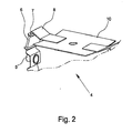
- the Fig. 2 shows in detail a part of belonging to an inventive magnetic-inductive flowmeter 1 magnetic field generating device 4.
- a magnetic coil 6 the coil core 7, which adjoins the coil core 7 magnetic connecting element 8, integrally connected to the coil core 7, and the yoke element 10.
- the two electrodes 5 are respectively provided on the narrow sides of the "inner” measuring tube 2 or on the narrow sides of the measuring section 3.
- the coil cores 7, the magnetic connecting elements 8 and / or the yoke elements 10, to eddy currents can be carried out layered, the individual layers are of course electrically isolated from each other.
- a support element 13 is provided on each longitudinal side of the measuring section 3 between the "outer” measuring tube 2 and the “inner” measuring tube 2, and that, like the Fig. 4 shows, in the area of the electrodes 5 and the magnet coils 6, a cover element 14 applied externally to the measuring tube 2 is provided.
- a magnetic-inductive flowmeter 1 For the illustrated exemplary embodiment of a magnetic-inductive flowmeter 1 according to the invention, only one yoke element 10 is provided on each longitudinal side of the "inner" measuring tube 2, that is to say on each longitudinal side of the measuring section 3, which has a substantially rectangular cross-section, on its two narrow sides each with a magnetic connection element 8 is magnetically well connected.
- the magnetic field generating device 4 then only works if the magnetic coils 6 magnetically connected via the coil cores 7 and the magnetic connecting elements 8 to the yoke element 10 produce rectified magnetic fields.
- the north poles of the individual magnetic coils are each marked with an "N", the south poles each with an "S".
- magnetic-inductive flowmeters 1 with only one yoke element 10 on one longitudinal side of the measuring section 3 and only one further yoke element 10 on the other longitudinal side of the measuring section 3 is readily possible, it is also possible to have two yoke elements 10 on each longitudinal side of the measuring section 3 provide. In this case, the two yoke elements 10 provided on one side of the measuring section 3 are then separated by a gap.
- the magnetic coils 6 and in particular their turns are made flat to keep the space occupied by the magnetic coils 6 as small as possible.
- the yoke elements 10 are substantially wider than the magnetic connecting elements 8 and the coil cores 7 executed.
- the functional magnetic field is "extended" in the flow direction of the measuring fluid.
Landscapes
- Physics & Mathematics (AREA)
- Electromagnetism (AREA)
- Fluid Mechanics (AREA)
- General Physics & Mathematics (AREA)
- Measuring Volume Flow (AREA)
Applications Claiming Priority (1)
| Application Number | Priority Date | Filing Date | Title |
|---|---|---|---|
| DE102012014266.8A DE102012014266A1 (de) | 2012-07-19 | 2012-07-19 | Magnetisch-induktives Durchflussmessgerät |
Publications (3)
| Publication Number | Publication Date |
|---|---|
| EP2687827A2 true EP2687827A2 (fr) | 2014-01-22 |
| EP2687827A3 EP2687827A3 (fr) | 2015-07-01 |
| EP2687827B1 EP2687827B1 (fr) | 2023-05-10 |
Family
ID=48874091
Family Applications (1)
| Application Number | Title | Priority Date | Filing Date |
|---|---|---|---|
| EP13003422.6A Active EP2687827B1 (fr) | 2012-07-19 | 2013-07-08 | Débitmètre à induction magnétique |
Country Status (4)
| Country | Link |
|---|---|
| US (1) | US9121739B2 (fr) |
| EP (1) | EP2687827B1 (fr) |
| CN (1) | CN103575342B (fr) |
| DE (1) | DE102012014266A1 (fr) |
Families Citing this family (9)
| Publication number | Priority date | Publication date | Assignee | Title |
|---|---|---|---|---|
| KR101978776B1 (ko) * | 2013-02-28 | 2019-05-16 | 삼성전자주식회사 | 다수의 안테나를 사용하는 이동통신 시스템에서 피드백 송수신 방법 및 장치 |
| US20150373744A1 (en) * | 2013-03-04 | 2015-12-24 | Nokia Technologies Oy | Synchronized physical layer reconfiguration among user equipment, macrocell, and small cell in macrocell-assisted small cell deployments |
| CA2910662C (fr) * | 2013-04-26 | 2017-10-31 | Huawei Technologies Co., Ltd. | Procede de transmission de donnees, station de base, et dispositif de telecommunication sans fil |
| DE102014113409A1 (de) * | 2014-09-17 | 2016-03-17 | Endress+Hauser Flowtec Ag | Magnetisch-induktives Durchflussmessgerät mit einem Magnetsystem mit mindestens vier Spulen |
| DE102015116679A1 (de) * | 2015-01-14 | 2016-07-14 | Krohne Ag | Magnetisch-induktives Durchflussmessgerät |
| US9631961B2 (en) * | 2015-08-19 | 2017-04-25 | Sensus Spectrum Llc | Inductive flow meter including extended magnetic pole pieces |
| DE102019123528B4 (de) | 2019-09-03 | 2024-05-08 | Krohne Ag | Magnetisch-induktives Durchflussmessgerät und Magnetkreisvorrichtung |
| CN111307027B (zh) * | 2020-02-28 | 2021-10-29 | 北京纳米能源与系统研究所 | 机电一体式自供能位置传感装置及流体流量传感器 |
| JP2024002967A (ja) * | 2022-06-23 | 2024-01-11 | クローネ アクチェンゲゼルシャフト | 磁気誘導式流量測定装置 |
Citations (1)
| Publication number | Priority date | Publication date | Assignee | Title |
|---|---|---|---|---|
| DE102006060442A1 (de) | 2006-12-19 | 2008-06-26 | Endress + Hauser Flowtec Ag | Vorrichtung zum Messen des Volumen- oder Massestroms eines Mediums in einer Rohrleitung |
Family Cites Families (21)
| Publication number | Priority date | Publication date | Assignee | Title |
|---|---|---|---|---|
| US4409846A (en) * | 1979-02-08 | 1983-10-18 | Aichi Tokei Denki Co., Ltd. | Electromagnetic flow meter |
| DE3031997C2 (de) * | 1980-08-25 | 1986-01-16 | Licentia Patent-Verwaltungs-Gmbh, 6000 Frankfurt | Anordnung zur berührungslosen Messung statischer und dynamischer Drehmomente |
| JPS57200821A (en) * | 1981-06-05 | 1982-12-09 | Aichi Tokei Denki Co Ltd | Electromagnetic flow meter |
| US4470309A (en) * | 1981-07-06 | 1984-09-11 | Tokyo Shibaura Denki Kabushiki Kaisha | Electromagnetic flowmeter |
| DE3401377C2 (de) * | 1984-01-17 | 1986-11-13 | Danfoss A/S, Nordborg | Elektromagnetischer Durchflußmesser |
| JPH0713584B2 (ja) * | 1986-01-31 | 1995-02-15 | 愛知時計電機株式会社 | 残留磁気型電磁流量計を用いた熱量計 |
| JPS62188910A (ja) * | 1986-02-14 | 1987-08-18 | Aichi Tokei Denki Co Ltd | 電磁流量計 |
| DE3870125D1 (de) * | 1987-10-01 | 1992-05-21 | Flowtec Ag | Magnetisch-induktive durchflussmessanordnung. |
| EP0649005B1 (fr) * | 1993-10-14 | 1997-04-23 | Endress + Hauser Flowtec AG | Capteurs de débimètre électromagnétique |
| JP4303039B2 (ja) * | 2002-09-25 | 2009-07-29 | 株式会社東芝 | 容量式電磁流量計 |
| JP2004233203A (ja) * | 2003-01-30 | 2004-08-19 | Yamatake Corp | 電磁流量計用測定管 |
| US6983661B2 (en) * | 2003-05-15 | 2006-01-10 | Endress + Hauser Flowtec Ag | Electromagnetic flow sensor |
| WO2005124292A1 (fr) * | 2004-06-16 | 2005-12-29 | Endress + Hauser Flowtec Ag | Capteur de debit a induction magnetique |
| GB2440964B (en) * | 2006-08-18 | 2011-08-10 | Abb Ltd | Flow meter |
| DE102007032879A1 (de) | 2007-07-12 | 2009-01-15 | Endress + Hauser Flowtec Ag | Vorrichtung zum Messen des Volumen- oder Massestroms eines mediums in einer Rohrleitung |
| JP4721073B2 (ja) * | 2008-04-18 | 2011-07-13 | Smc株式会社 | 電磁流量計 |
| DE102008035740A1 (de) * | 2008-07-31 | 2010-02-04 | Abb Technology Ag | Magnetisch induktiver Durchflussmesser mit einer kombinierte magnetische Flussleitmittel umfassenden Elektromagenteinheit |
| DE102008057755B4 (de) | 2008-11-17 | 2015-12-17 | Krohne Ag | Magnetisch-induktives Durchflußmeßgerät |
| DE102008057756A1 (de) | 2008-11-17 | 2010-05-27 | Krohne Ag | Magnetisch-induktives Durchflußmeßgerät |
| BRPI1104663A2 (pt) * | 2010-09-06 | 2013-01-15 | Mr Technologies S A | medidor de precisço para fluxos reduzidos |
| DE102012017904A1 (de) * | 2012-08-21 | 2014-03-20 | Krohne Ag | Magnetisch-induktives Durchflussmessgerät und Verfahren zu seiner Herstellung |
-
2012
- 2012-07-19 DE DE102012014266.8A patent/DE102012014266A1/de active Pending
-
2013
- 2013-07-08 EP EP13003422.6A patent/EP2687827B1/fr active Active
- 2013-07-19 CN CN201310304279.8A patent/CN103575342B/zh active Active
- 2013-07-19 US US13/946,164 patent/US9121739B2/en active Active
Patent Citations (1)
| Publication number | Priority date | Publication date | Assignee | Title |
|---|---|---|---|---|
| DE102006060442A1 (de) | 2006-12-19 | 2008-06-26 | Endress + Hauser Flowtec Ag | Vorrichtung zum Messen des Volumen- oder Massestroms eines Mediums in einer Rohrleitung |
Also Published As
| Publication number | Publication date |
|---|---|
| EP2687827A3 (fr) | 2015-07-01 |
| CN103575342B (zh) | 2020-08-14 |
| CN103575342A (zh) | 2014-02-12 |
| US9121739B2 (en) | 2015-09-01 |
| DE102012014266A1 (de) | 2014-01-23 |
| US20140020477A1 (en) | 2014-01-23 |
| EP2687827B1 (fr) | 2023-05-10 |
Similar Documents
| Publication | Publication Date | Title |
|---|---|---|
| EP2687827B1 (fr) | Débitmètre à induction magnétique | |
| EP2440886B1 (fr) | Débitmètre à induction magnétique | |
| DE102012221616B4 (de) | Magnetisch induktiver Durchflussmesser | |
| DE102011119982A1 (de) | Magnetisch-induktives Durchflussmessgerät | |
| DE102014104107A9 (de) | Elektromagnetischer Strömungsmesser | |
| EP2761257A1 (fr) | Appareil de mesure de débit à induction magnétique | |
| DE102011079352A1 (de) | Magnetisch-induktives Durchflussmessgerät | |
| DE102015116679A1 (de) | Magnetisch-induktives Durchflussmessgerät | |
| DE102012017904A1 (de) | Magnetisch-induktives Durchflussmessgerät und Verfahren zu seiner Herstellung | |
| DE102014113408A1 (de) | Verfahren zur Herstellung eines Magnetisch-induktives Durchfluss- messgeräts mit zum Teil reduziertem Querschnitt | |
| EP2844958B1 (fr) | Appareil de mesure de débit à induction magnétique | |
| EP3211384B1 (fr) | Débitmètre inductif-magnétique et procédé associé | |
| EP2761256B1 (fr) | Système à bobine pour un appareil de mesure à induction magnétique | |
| DE202009017274U1 (de) | Magnetisch-induktiver Durchflussmesser | |
| DE102005028572B4 (de) | Stromsensoranordung mit einem Magnetkern | |
| DE102009001413A1 (de) | Spulenanordnung für ein magnetisch induktives Durchflussmessgerät | |
| DE102014113409A1 (de) | Magnetisch-induktives Durchflussmessgerät mit einem Magnetsystem mit mindestens vier Spulen | |
| EP0179285B2 (fr) | Débitmètre magnéto-inductif | |
| DE102004063020B4 (de) | Magnetisch-induktives Durchflußmeßgerät | |
| DE102015122664B4 (de) | Magnetisch-induktives Durchflussmessgerät | |
| DE3435910A1 (de) | Magnetisch-induktiver durchflussmesser mit auswechselbaren durchflusssensoren | |
| EP2400274B1 (fr) | Dispositif de mesure de flux de liquide, dispositif de ventilation et procédé de mesure | |
| EP3058318A1 (fr) | Tube de mesure pour systèmes de mesure de débit magnéto-inductifs | |
| EP3045875B1 (fr) | Débitmètre à induction magnétique | |
| DE102014216535A1 (de) | Magnetisch-induktives Durchflussmessgerät |
Legal Events
| Date | Code | Title | Description |
|---|---|---|---|
| PUAI | Public reference made under article 153(3) epc to a published international application that has entered the european phase |
Free format text: ORIGINAL CODE: 0009012 |
|
| AK | Designated contracting states |
Kind code of ref document: A2 Designated state(s): AL AT BE BG CH CY CZ DE DK EE ES FI FR GB GR HR HU IE IS IT LI LT LU LV MC MK MT NL NO PL PT RO RS SE SI SK SM TR |
|
| AX | Request for extension of the european patent |
Extension state: BA ME |
|
| PUAL | Search report despatched |
Free format text: ORIGINAL CODE: 0009013 |
|
| AK | Designated contracting states |
Kind code of ref document: A3 Designated state(s): AL AT BE BG CH CY CZ DE DK EE ES FI FR GB GR HR HU IE IS IT LI LT LU LV MC MK MT NL NO PL PT RO RS SE SI SK SM TR |
|
| AX | Request for extension of the european patent |
Extension state: BA ME |
|
| RIC1 | Information provided on ipc code assigned before grant |
Ipc: G01F 1/56 20060101AFI20150526BHEP Ipc: G01F 1/58 20060101ALI20150526BHEP |
|
| 17P | Request for examination filed |
Effective date: 20160104 |
|
| RBV | Designated contracting states (corrected) |
Designated state(s): AL AT BE BG CH CY CZ DE DK EE ES FI FR GB GR HR HU IE IS IT LI LT LU LV MC MK MT NL NO PL PT RO RS SE SI SK SM TR |
|
| STAA | Information on the status of an ep patent application or granted ep patent |
Free format text: STATUS: EXAMINATION IS IN PROGRESS |
|
| 17Q | First examination report despatched |
Effective date: 20171027 |
|
| GRAP | Despatch of communication of intention to grant a patent |
Free format text: ORIGINAL CODE: EPIDOSNIGR1 |
|
| STAA | Information on the status of an ep patent application or granted ep patent |
Free format text: STATUS: GRANT OF PATENT IS INTENDED |
|
| GRAS | Grant fee paid |
Free format text: ORIGINAL CODE: EPIDOSNIGR3 |
|
| INTG | Intention to grant announced |
Effective date: 20221124 |
|
| GRAA | (expected) grant |
Free format text: ORIGINAL CODE: 0009210 |
|
| STAA | Information on the status of an ep patent application or granted ep patent |
Free format text: STATUS: THE PATENT HAS BEEN GRANTED |
|
| AK | Designated contracting states |
Kind code of ref document: B1 Designated state(s): AL AT BE BG CH CY CZ DE DK EE ES FI FR GB GR HR HU IE IS IT LI LT LU LV MC MK MT NL NO PL PT RO RS SE SI SK SM TR |
|
| REG | Reference to a national code |
Ref country code: GB Ref legal event code: FG4D Free format text: NOT ENGLISH |
|
| REG | Reference to a national code |
Ref country code: AT Ref legal event code: REF Ref document number: 1567092 Country of ref document: AT Kind code of ref document: T Effective date: 20230515 Ref country code: CH Ref legal event code: EP |
|
| REG | Reference to a national code |
Ref country code: DE Ref legal event code: R096 Ref document number: 502013016373 Country of ref document: DE |
|
| REG | Reference to a national code |
Ref country code: IE Ref legal event code: FG4D Free format text: LANGUAGE OF EP DOCUMENT: GERMAN |
|
| P01 | Opt-out of the competence of the unified patent court (upc) registered |
Effective date: 20230607 |
|
| REG | Reference to a national code |
Ref country code: NL Ref legal event code: FP |
|
| REG | Reference to a national code |
Ref country code: LT Ref legal event code: MG9D |
|
| PG25 | Lapsed in a contracting state [announced via postgrant information from national office to epo] |
Ref country code: SE Free format text: LAPSE BECAUSE OF FAILURE TO SUBMIT A TRANSLATION OF THE DESCRIPTION OR TO PAY THE FEE WITHIN THE PRESCRIBED TIME-LIMIT Effective date: 20230510 Ref country code: PT Free format text: LAPSE BECAUSE OF FAILURE TO SUBMIT A TRANSLATION OF THE DESCRIPTION OR TO PAY THE FEE WITHIN THE PRESCRIBED TIME-LIMIT Effective date: 20230911 Ref country code: NO Free format text: LAPSE BECAUSE OF FAILURE TO SUBMIT A TRANSLATION OF THE DESCRIPTION OR TO PAY THE FEE WITHIN THE PRESCRIBED TIME-LIMIT Effective date: 20230810 Ref country code: ES Free format text: LAPSE BECAUSE OF FAILURE TO SUBMIT A TRANSLATION OF THE DESCRIPTION OR TO PAY THE FEE WITHIN THE PRESCRIBED TIME-LIMIT Effective date: 20230510 |
|
| PG25 | Lapsed in a contracting state [announced via postgrant information from national office to epo] |
Ref country code: RS Free format text: LAPSE BECAUSE OF FAILURE TO SUBMIT A TRANSLATION OF THE DESCRIPTION OR TO PAY THE FEE WITHIN THE PRESCRIBED TIME-LIMIT Effective date: 20230510 Ref country code: PL Free format text: LAPSE BECAUSE OF FAILURE TO SUBMIT A TRANSLATION OF THE DESCRIPTION OR TO PAY THE FEE WITHIN THE PRESCRIBED TIME-LIMIT Effective date: 20230510 Ref country code: LV Free format text: LAPSE BECAUSE OF FAILURE TO SUBMIT A TRANSLATION OF THE DESCRIPTION OR TO PAY THE FEE WITHIN THE PRESCRIBED TIME-LIMIT Effective date: 20230510 Ref country code: LT Free format text: LAPSE BECAUSE OF FAILURE TO SUBMIT A TRANSLATION OF THE DESCRIPTION OR TO PAY THE FEE WITHIN THE PRESCRIBED TIME-LIMIT Effective date: 20230510 Ref country code: IS Free format text: LAPSE BECAUSE OF FAILURE TO SUBMIT A TRANSLATION OF THE DESCRIPTION OR TO PAY THE FEE WITHIN THE PRESCRIBED TIME-LIMIT Effective date: 20230910 Ref country code: HR Free format text: LAPSE BECAUSE OF FAILURE TO SUBMIT A TRANSLATION OF THE DESCRIPTION OR TO PAY THE FEE WITHIN THE PRESCRIBED TIME-LIMIT Effective date: 20230510 Ref country code: GR Free format text: LAPSE BECAUSE OF FAILURE TO SUBMIT A TRANSLATION OF THE DESCRIPTION OR TO PAY THE FEE WITHIN THE PRESCRIBED TIME-LIMIT Effective date: 20230811 |
|
| PG25 | Lapsed in a contracting state [announced via postgrant information from national office to epo] |
Ref country code: FI Free format text: LAPSE BECAUSE OF FAILURE TO SUBMIT A TRANSLATION OF THE DESCRIPTION OR TO PAY THE FEE WITHIN THE PRESCRIBED TIME-LIMIT Effective date: 20230510 |
|
| PG25 | Lapsed in a contracting state [announced via postgrant information from national office to epo] |
Ref country code: SK Free format text: LAPSE BECAUSE OF FAILURE TO SUBMIT A TRANSLATION OF THE DESCRIPTION OR TO PAY THE FEE WITHIN THE PRESCRIBED TIME-LIMIT Effective date: 20230510 |
|
| PG25 | Lapsed in a contracting state [announced via postgrant information from national office to epo] |
Ref country code: SM Free format text: LAPSE BECAUSE OF FAILURE TO SUBMIT A TRANSLATION OF THE DESCRIPTION OR TO PAY THE FEE WITHIN THE PRESCRIBED TIME-LIMIT Effective date: 20230510 Ref country code: SK Free format text: LAPSE BECAUSE OF FAILURE TO SUBMIT A TRANSLATION OF THE DESCRIPTION OR TO PAY THE FEE WITHIN THE PRESCRIBED TIME-LIMIT Effective date: 20230510 Ref country code: RO Free format text: LAPSE BECAUSE OF FAILURE TO SUBMIT A TRANSLATION OF THE DESCRIPTION OR TO PAY THE FEE WITHIN THE PRESCRIBED TIME-LIMIT Effective date: 20230510 Ref country code: EE Free format text: LAPSE BECAUSE OF FAILURE TO SUBMIT A TRANSLATION OF THE DESCRIPTION OR TO PAY THE FEE WITHIN THE PRESCRIBED TIME-LIMIT Effective date: 20230510 Ref country code: DK Free format text: LAPSE BECAUSE OF FAILURE TO SUBMIT A TRANSLATION OF THE DESCRIPTION OR TO PAY THE FEE WITHIN THE PRESCRIBED TIME-LIMIT Effective date: 20230510 Ref country code: CZ Free format text: LAPSE BECAUSE OF FAILURE TO SUBMIT A TRANSLATION OF THE DESCRIPTION OR TO PAY THE FEE WITHIN THE PRESCRIBED TIME-LIMIT Effective date: 20230510 |
|
| REG | Reference to a national code |
Ref country code: DE Ref legal event code: R097 Ref document number: 502013016373 Country of ref document: DE |
|
| PG25 | Lapsed in a contracting state [announced via postgrant information from national office to epo] |
Ref country code: MC Free format text: LAPSE BECAUSE OF FAILURE TO SUBMIT A TRANSLATION OF THE DESCRIPTION OR TO PAY THE FEE WITHIN THE PRESCRIBED TIME-LIMIT Effective date: 20230510 |
|
| PG25 | Lapsed in a contracting state [announced via postgrant information from national office to epo] |
Ref country code: MC Free format text: LAPSE BECAUSE OF FAILURE TO SUBMIT A TRANSLATION OF THE DESCRIPTION OR TO PAY THE FEE WITHIN THE PRESCRIBED TIME-LIMIT Effective date: 20230510 |
|
| PLBE | No opposition filed within time limit |
Free format text: ORIGINAL CODE: 0009261 |
|
| STAA | Information on the status of an ep patent application or granted ep patent |
Free format text: STATUS: NO OPPOSITION FILED WITHIN TIME LIMIT |
|
| REG | Reference to a national code |
Ref country code: BE Ref legal event code: MM Effective date: 20230731 |
|
| PG25 | Lapsed in a contracting state [announced via postgrant information from national office to epo] |
Ref country code: LU Free format text: LAPSE BECAUSE OF NON-PAYMENT OF DUE FEES Effective date: 20230708 |
|
| PG25 | Lapsed in a contracting state [announced via postgrant information from national office to epo] |
Ref country code: LU Free format text: LAPSE BECAUSE OF NON-PAYMENT OF DUE FEES Effective date: 20230708 |
|
| 26N | No opposition filed |
Effective date: 20240213 |
|
| GBPC | Gb: european patent ceased through non-payment of renewal fee |
Effective date: 20230810 |
|
| REG | Reference to a national code |
Ref country code: IE Ref legal event code: MM4A |
|
| PG25 | Lapsed in a contracting state [announced via postgrant information from national office to epo] |
Ref country code: SI Free format text: LAPSE BECAUSE OF FAILURE TO SUBMIT A TRANSLATION OF THE DESCRIPTION OR TO PAY THE FEE WITHIN THE PRESCRIBED TIME-LIMIT Effective date: 20230510 |
|
| PG25 | Lapsed in a contracting state [announced via postgrant information from national office to epo] |
Ref country code: SI Free format text: LAPSE BECAUSE OF FAILURE TO SUBMIT A TRANSLATION OF THE DESCRIPTION OR TO PAY THE FEE WITHIN THE PRESCRIBED TIME-LIMIT Effective date: 20230510 Ref country code: IT Free format text: LAPSE BECAUSE OF FAILURE TO SUBMIT A TRANSLATION OF THE DESCRIPTION OR TO PAY THE FEE WITHIN THE PRESCRIBED TIME-LIMIT Effective date: 20230510 Ref country code: BE Free format text: LAPSE BECAUSE OF NON-PAYMENT OF DUE FEES Effective date: 20230731 |
|
| PG25 | Lapsed in a contracting state [announced via postgrant information from national office to epo] |
Ref country code: IE Free format text: LAPSE BECAUSE OF NON-PAYMENT OF DUE FEES Effective date: 20230708 |
|
| PG25 | Lapsed in a contracting state [announced via postgrant information from national office to epo] |
Ref country code: GB Free format text: LAPSE BECAUSE OF NON-PAYMENT OF DUE FEES Effective date: 20230810 |
|
| PG25 | Lapsed in a contracting state [announced via postgrant information from national office to epo] |
Ref country code: IE Free format text: LAPSE BECAUSE OF NON-PAYMENT OF DUE FEES Effective date: 20230708 Ref country code: GB Free format text: LAPSE BECAUSE OF NON-PAYMENT OF DUE FEES Effective date: 20230810 |
|
| REG | Reference to a national code |
Ref country code: AT Ref legal event code: MM01 Ref document number: 1567092 Country of ref document: AT Kind code of ref document: T Effective date: 20230708 |
|
| PG25 | Lapsed in a contracting state [announced via postgrant information from national office to epo] |
Ref country code: AT Free format text: LAPSE BECAUSE OF NON-PAYMENT OF DUE FEES Effective date: 20230708 |
|
| PG25 | Lapsed in a contracting state [announced via postgrant information from national office to epo] |
Ref country code: AT Free format text: LAPSE BECAUSE OF NON-PAYMENT OF DUE FEES Effective date: 20230708 |
|
| PG25 | Lapsed in a contracting state [announced via postgrant information from national office to epo] |
Ref country code: BG Free format text: LAPSE BECAUSE OF FAILURE TO SUBMIT A TRANSLATION OF THE DESCRIPTION OR TO PAY THE FEE WITHIN THE PRESCRIBED TIME-LIMIT Effective date: 20230510 |
|
| PG25 | Lapsed in a contracting state [announced via postgrant information from national office to epo] |
Ref country code: BG Free format text: LAPSE BECAUSE OF FAILURE TO SUBMIT A TRANSLATION OF THE DESCRIPTION OR TO PAY THE FEE WITHIN THE PRESCRIBED TIME-LIMIT Effective date: 20230510 |
|
| PG25 | Lapsed in a contracting state [announced via postgrant information from national office to epo] |
Ref country code: CY Free format text: LAPSE BECAUSE OF FAILURE TO SUBMIT A TRANSLATION OF THE DESCRIPTION OR TO PAY THE FEE WITHIN THE PRESCRIBED TIME-LIMIT; INVALID AB INITIO Effective date: 20130708 |
|
| PG25 | Lapsed in a contracting state [announced via postgrant information from national office to epo] |
Ref country code: HU Free format text: LAPSE BECAUSE OF FAILURE TO SUBMIT A TRANSLATION OF THE DESCRIPTION OR TO PAY THE FEE WITHIN THE PRESCRIBED TIME-LIMIT; INVALID AB INITIO Effective date: 20130708 |
|
| PGFP | Annual fee paid to national office [announced via postgrant information from national office to epo] |
Ref country code: NL Payment date: 20250721 Year of fee payment: 13 |
|
| PGFP | Annual fee paid to national office [announced via postgrant information from national office to epo] |
Ref country code: DE Payment date: 20250917 Year of fee payment: 13 |
|
| PGFP | Annual fee paid to national office [announced via postgrant information from national office to epo] |
Ref country code: FR Payment date: 20250725 Year of fee payment: 13 |
|
| PGFP | Annual fee paid to national office [announced via postgrant information from national office to epo] |
Ref country code: CH Payment date: 20250801 Year of fee payment: 13 |
|
| PG25 | Lapsed in a contracting state [announced via postgrant information from national office to epo] |
Ref country code: TR Free format text: LAPSE BECAUSE OF FAILURE TO SUBMIT A TRANSLATION OF THE DESCRIPTION OR TO PAY THE FEE WITHIN THE PRESCRIBED TIME-LIMIT Effective date: 20230510 |