EP2687833A1 - Drehmomentsensor - Google Patents
Drehmomentsensor Download PDFInfo
- Publication number
- EP2687833A1 EP2687833A1 EP12760559.0A EP12760559A EP2687833A1 EP 2687833 A1 EP2687833 A1 EP 2687833A1 EP 12760559 A EP12760559 A EP 12760559A EP 2687833 A1 EP2687833 A1 EP 2687833A1
- Authority
- EP
- European Patent Office
- Prior art keywords
- magnetism collecting
- collecting ring
- magnetism
- ring
- inner peripheral
- Prior art date
- Legal status (The legal status is an assumption and is not a legal conclusion. Google has not performed a legal analysis and makes no representation as to the accuracy of the status listed.)
- Granted
Links
Images




Classifications
-
- G—PHYSICS
- G01—MEASURING; TESTING
- G01L—MEASURING FORCE, STRESS, TORQUE, WORK, MECHANICAL POWER, MECHANICAL EFFICIENCY, OR FLUID PRESSURE
- G01L3/00—Measuring torque, work, mechanical power, or mechanical efficiency, in general
- G01L3/02—Rotary-transmission dynamometers
- G01L3/04—Rotary-transmission dynamometers wherein the torque-transmitting element comprises a torsionally-flexible shaft
- G01L3/10—Rotary-transmission dynamometers wherein the torque-transmitting element comprises a torsionally-flexible shaft involving electric or magnetic means for indicating
- G01L3/101—Rotary-transmission dynamometers wherein the torque-transmitting element comprises a torsionally-flexible shaft involving electric or magnetic means for indicating involving magnetic or electromagnetic means
-
- G—PHYSICS
- G01—MEASURING; TESTING
- G01L—MEASURING FORCE, STRESS, TORQUE, WORK, MECHANICAL POWER, MECHANICAL EFFICIENCY, OR FLUID PRESSURE
- G01L3/00—Measuring torque, work, mechanical power, or mechanical efficiency, in general
- G01L3/02—Rotary-transmission dynamometers
- G01L3/04—Rotary-transmission dynamometers wherein the torque-transmitting element comprises a torsionally-flexible shaft
- G01L3/10—Rotary-transmission dynamometers wherein the torque-transmitting element comprises a torsionally-flexible shaft involving electric or magnetic means for indicating
- G01L3/101—Rotary-transmission dynamometers wherein the torque-transmitting element comprises a torsionally-flexible shaft involving electric or magnetic means for indicating involving magnetic or electromagnetic means
- G01L3/104—Rotary-transmission dynamometers wherein the torque-transmitting element comprises a torsionally-flexible shaft involving electric or magnetic means for indicating involving magnetic or electromagnetic means involving permanent magnets
Definitions
- the present invention relates to a torque sensor that detects torque acting on a shaft in accordance with a magnetic flux density conducted from a magnet.
- JP2009-244134A discloses a non-contact type torque sensor that detects steering torque acting on a steering shaft using magnetic force.
- the torque sensor includes an input shaft and an output shaft supported in a housing to be free to rotate, a torsion bar that transmits the steering torque between the input shaft and the output shaft, a magnetism generating portion fixed to the input shaft, a rotary magnetic circuit portion fixed to the output shaft, a fixed magnetic circuit portion fixed to the housing, and a magnetism sensor that detects a magnetic flux density conducted to the fixed magnetic circuit portion.
- the rotary magnetic circuit portion includes a pair of soft magnetic rings
- the fixed magnetic circuit portion includes a pair of magnetism collecting rings surrounding the respective soft magnetic rings.
- the magnetism collecting rings are fitted into annular grooves formed in the housing.
- the magnetism collecting rings are caulked to the housing by deforming an inner peripheral wall of the housing such that edge portions of the respective annular grooves contact axial direction end surfaces of the magnetism collecting rings.
- the magnetism collecting rings may disengage from the annular grooves depending on a caulking condition, and therefore the magnetism collecting rings must be attached to the housing more securely.
- a torque sensor is configured to detect torque acting on a torsion bar coupling a first shaft and a second shaft that are supported in a housing to be free to rotate.
- the torque sensor includes a magnetism generating portion fixed to the first shaft, a rotary magnetic circuit portion fixed to the second shaft, a magnetism collecting ring attached to the housing so as to face the rotary magnetic circuit portion, and a magnetism detector that is configured to detect a magnetic flux density that is conducted from the magnetism generating portion to the magnetism collecting ring via the rotary magnetic circuit portion when the torsion bar undergoes torsional deformation.
- the magnetism collecting ring is an annular member formed such that an axial direction end portion thereof is thinner than a central portion.
- the housing includes an annular groove formed to be capable of accommodating the magnetism collecting ring and provided as a recess in an inner peripheral wall of the housing so as to be deeper than a thickness of the end portion of the magnetism collecting ring, and a caulk portion provided in the inner peripheral wall to caulk the magnetism collecting ring by covering the end portion of the magnetism collecting ring that is fitted into the annular groove.
- a power steering apparatus 1 for a vehicle according to a first embodiment of the present invention will be described below with reference to the figures.
- the power steering apparatus 1 includes a steering shaft 10 linked to a steering wheel, and a rack shaft 2 linked to a vehicle wheel.
- the power steering apparatus 1 steers the vehicle wheel by rotating the steering shaft 10 so that the rack shaft 2 moves in an axial direction.
- the steering shaft 10 is a shaft member which is supported by an upper housing 20 and a lower housing 30 coupled by a bolt 21.
- the upper housing 20 and the lower housing 30 are formed from an alloy of a non-magnetic material such as aluminum alloy.
- the steering shaft 10 includes an input shaft 11 serving as a first shaft, a torsion bar 12, and an output shaft 13 serving as a second shaft.
- the input shaft 11 is supported by the upper housing 20 via a roller bearing 22 to be free to rotate.
- the input shaft 11 and the upper housing 20 are sealed from each other by a dust seal 23.
- the dust seal 23 is disposed above the roller bearing 22.
- the output shaft 13 is supported to be free to rotate by a roller bearing 31 sandwiched between a lower end portion of the upper housing 20 and an upper end portion of the lower housing 30, and a slide bearing 32 disposed in a lower end portion of the lower housing 30,
- An accommodation chamber 13A capable of accommodating a lower end portion of the input shaft 11 is formed in an upper end portion of the output shaft 13.
- a slide bearing 14 is interposed between an inner peripheral surface of the accommodation chamber 13A of the output shaft 13 and an outer peripheral surface of the lower end portion of the input shaft 11.
- the input shaft I 1 is formed in a cylindrical shape, and the torsion bar 12 is housed in an interior of the input shaft 11 coaxially therewith. An upper end portion of the torsion bar 12 is coupled to an upper end portion of the input shaft 11 via a pin 15.
- a lower end portion of the torsion bar 12 projects downward from a lower end opening portion of the input shaft 11.
- a serration 12A is formed on an outer peripheral surface of the lower end portion of the torsion bar 12.
- the lower end portion of the torsion bar 12 is coupled via the serration 12A to an engagement hole 13B formed in a bottom portion of the accommodation chamber 13A.
- the torsion bar 12 transmits steering torque input into the input shaft 11 to the output shaft 13, and undergoes torsional deformation around a rotary axis O in accordance with the torque.
- a gear 13C is provided on an outer peripheral surface of the output shaft 13 toward the lower end thereof.
- the gear 13C of the output shaft 13 meshes with a rack gear 2A formed on the rack shaft 2.
- the power steering apparatus 1 includes, as an assist mechanism for applying auxiliary steering torque, a non-contact type torque sensor 40 that detects the steering torque acting on the torsion bar 12, and an electric motor that applies auxiliary steering torque to the rack shaft 2 in accordance with the detected steering torque.
- the torque sensor 40 includes a magnetism generating portion 50 that rotates together with the input shaft 11, a rotary magnetic circuit portion 60 that rotates together with the output shaft 13, a fixed magnetic circuit portion 70 fixed to the upper housing 20, and a magnetism sensor 81 that detects a magnetic flux density conducted to the fixed magnetic circuit portion 70.
- the torque sensor 40 detects the steering torque acting on the torsion bar 12 on the basis of an output of the magnetism sensor 81.
- the torque sensor 40 may be configured such that the magnetism generating portion 50 is provided on the output shaft 13 and the rotary magnetic circuit portion 60 is provided on the input shaft 11.
- the magnetism generating portion 50 includes a back yoke 51 that is press-fitted to the input shaft 11, and a ring magnet 52 fixed to a lower end surface of the back yoke 51 via an adhesive.
- the back yoke 51 is an annular member formed from an alloy of a soft magnetic material.
- a fitting hole 51A is formed in the back yoke 51 to penetrate in a rotary axis O direction, The back yoke 51 is press-fitted to the outer peripheral surface of the input shaft 11 via the fitting hole 51A.
- the ring magnet 52 is an annular member formed from sintered metal.
- the ring magnet 52 is a multipolar magnet formed by polarizing a hard magnetic material in the rotary axis O direction of the steering shaft 10.
- Twelve magnetic poles are formed on the ring magnet 52 at equal intervals in a circumferential direction.
- six N poles and six S poles are disposed alternately in the circumferential direction on an upper end surface and a lower end surface of the ring magnet 52.
- the number of magnetic poles provided on the ring magnet 52 is not limited to twelve, and may be set as desired according to necessity.
- the ring magnet 52 is fixed to the lower end surface of the back yoke 51 by an adhesive applied to the upper end surface of the ring magnet 52.
- the back yoke 51 is magnetized by a magnetic field of the ring magnet 52, and therefore the back yoke 51 and the ring magnet 52 are joined not only by an adhesive force of the adhesive, but also by magnetic force.
- the back yoke 51 functions as a yoke that conducts magnetic flux by linking adjacent magnetic poles of the ring magnet 52, with the result that magnetic force is concentrated on a lower magnetic pole surface, i.e. the lower end surface, of the ring magnet 52.
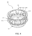
- the rotary magnetic circuit portion 60 includes a first soft magnetic ring 61 and a second soft magnetic ring 62 that conduct the magnetic flux output from the ring magnet 52, an attachment member 63 attached to the output shaft 13, and a resin mold 64 that fixes the first soft magnetic ring 61 and the second soft magnetic ring 62 to the attachment member 63. It should be noted that illustration of the resin mold 64 has been omitted from FIG. 4 .
- the first soft magnetic ring 61 includes an annular first magnetic path ring portion 61C, six first magnetic path column portions 61B projecting downward from the first magnetic path ring portion 61C, and first magnetic path end portions 61A that are bent inward from respective lower ends of the first magnetic path column portions 61B so as to face the lower end surface of the ring magnet 52.
- the second soft magnetic ring 62 includes an annular second magnetic path ring portion 62C, six second magnetic path column portions 62B projecting upward from the second magnetic path ring portion 62C, and second magnetic path end portions 62A that are bent inward from respective upper ends of the second magnetic path column portions 62B so as to face the lower end surface of the ring magnet 52.
- the first magnetic path ring portion 61C and the second magnetic path ring portion 62C are annular members respectively having entirely connected circumferences.
- the first magnetic path ring portion 61C and the second magnetic path ring portion 62C are disposed via an interval in the rotary axis O direction such that the first magnetic path end portions 61A and the second magnetic path end portions 62A are arranged alternately at equal angular intervals on an identical plane.
- the first magnetic path ring portion 61C is disposed above the ring magnet 52, whereas the second magnetic path ring portion 62C is disposed below the ring magnet 52.
- the ring magnet 52 is therefore disposed between the first magnetic path ring portion 61C and the second magnetic path ring portion 62C in the rotary axis O direction.
- the first magnetic path column portions 61B and the second magnetic path column portions 62B are respectively formed in a flat plate shape and provided to extend in the rotary axis O direction.
- the first magnetic path column portions 61B are disposed to surround the outer peripheral surface of the ring magnet 52 via a predetermined gap.
- the second magnetic path column portions 62B extend in an opposite direction to the first magnetic path column portions 61B along the rotary axis O.
- the first magnetic path end portions 61A and the second magnetic path end portions 62A are respectively formed in a flat plate shape. In a neutral condition where no steering torque acts on the torsion bar 12, respective center lines of the first magnetic path end portions 61A and the second magnetic path end portions 62A are set to indicate boundaries between the N poles and the S poles of the ring magnet 52.
- the fixed magnetic circuit portion 70 includes a first magnetism collecting ring 71 provided around an outer periphery of the first magnetic path ring portion 61C of the first soft magnetic ring 61, a second magnetism collecting ring 72 provided around an outer periphery of the second magnetic path ring portion 62C of the second soft magnetic ring 62, a first magnetism collecting yoke 73 connected to the first magnetism collecting ring 71, and a second magnetism collecting yoke 74 connected to the second magnetism collecting ring 72.
- the first magnetism collecting ring 71 is a substantially C-shaped annular member having a slit 71A
- the second magnetism collecting ring 72 is a substantially C-shaped annular member having a slit 72A.
- An upper-lower pair of annular grooves 24 are formed as recesses in an inner peripheral wall of the upper housing 20.
- the first magnetism collecting ring 71 is caulked to the upper housing 20 while fitted into the upper side annular groove 24, and the second magnetism collecting ring 72 is caulked to the upper housing 20 while fitted into the lower side annular groove 24.
- the first magnetism collecting ring 71 and the second magnetism collecting ring 72 are disposed to surround the rotary magnetic circuit portion 60.
- An inner peripheral surface of the first magnetism collecting ring 71 faces the first magnetic path ring portion 61C of the first soft magnetic ring 61
- an inner peripheral surface of the second magnetism collecting ring 72 faces the second magnetic path ring portion 62C of the second soft magnetic ring 62.
- the first magnetism collecting yoke 73 and the second magnetism collecting yoke 74 are block-shaped members.
- the first magnetism collecting yoke 73 is provided to contact the outer peripheral surface of the first magnetism collecting ring 7 1
- the second magnetism collecting yoke 74 is provided to contact the outer peripheral surface of the second magnetism collecting ring 72.
- a pair of magnetic gaps arranged side by side in the circumferential direction are formed between the first magnetism collecting yoke 73 and the second magnetism collecting yoke 74.
- One magnetism sensor 81 is disposed in each magnetic gap.
- the first magnetism collecting yoke 73, the second magnetism collecting yoke 74, the magnetism sensor 81, and a substrate 82 connected to the magnetism sensor 81 are disposed in a sensor holder 83.
- the resin sensor holder 83 is fixed to the metal upper housing 20 via a pair of bolts 84.
- the magnetism sensor 81 is a magnetism detector that detects a magnetic flux density conducted from the magnetism generating portion 50 to the first magnetism collecting ring 71 and second magnetism collecting ring 72 via the rotary magnetic circuit portion 60 in response to the torsional deformation of the torsion bar 12.
- the magnetism sensor 81 outputs a voltage as a signal corresponding to the magnetic flux density passing through a Hall element.
- the output signal of the magnetism sensor 81 is transmitted to a controller via a terminal 83A provided in the sensor holder 83.
- the magnetism sensor 81 may also be provided with a circuit that amplifies the signal from the Hall element, a circuit that performs temperature compensation, a noise filtering circuit, and so on.
- the first magnetic path end portions 61A of the first soft magnetic ring 61 and the second magnetic path end portions 62A of the second soft magnetic ring 62 respectively face the N poles and S poles of the ring magnet 52 by identical surface areas, and therefore the respective poles are magnetically short-circuited. Magnetic flux is not therefore conducted to the rotary magnetic circuit portion 60 and the fixed magnetic circuit portion 70.
- the torsion bar 12 undergoes torsional deformation in accordance with the direction of the steering torque.
- the first magnetic path end portions 61A face the N poles by a larger surface area than the S poles
- the second magnetic path end portions 62A face the S poles by a larger surface area than the N poles.
- Magnetic flux from the ring magnet 52 is conducted to the rotary magnetic circuit portion 60 and the fixed magnetic circuit portion 70, whereupon the magnetism sensor 81 outputs a signal corresponding to a intensity and a direction of the magnetic field.
- a magnetic path extends from the N pole to the S pole via the first soft magnetic ring 61, the first magnetism collecting ring 71, the first magnetism collecting yoke 73, the magnetism sensor 81, the second magnetism collecting yoke 74, the second magnetism collecting ring 72, and the second soft magnetic ring 62.
- the torsion bar 12 undergoes torsional deformation in the opposite direction.
- the first magnetic path end portions 61A face the S poles by a larger surface area than the N poles
- the second magnetic path end portions 62A face the N poles by a larger surface area than the S poles.
- Magnetic flux from the ring magnet 52 is conducted along an opposite magnetic path to the magnetic path described above, whereupon the magnetism sensor 81 outputs a signal corresponding to the intensity and the direction of the magnetic field.
- the magnetic path extends from the N pole to the S pole via the second soft magnetic ring 62, the second magnetism collecting ring 72, the second magnetism collecting yoke 74, the magnetism sensor 8 1, the first magnetism collecting yoke 73, the first magnetism collecting ring 71, and the first soft magnetic ring 1.
- the magnetic fields in the magnetic gaps become steadily more intense.
- the output signal of the magnetism sensor 81 also increases.
- the steering torque acting on the torsion bar 12 is detected on the basis of the signal output from the magnetism sensor 81.
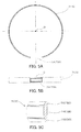
- the first magnetism collecting ring 71 is an annular member formed from a soft magnetic material.
- the slit 71A is formed in the first magnetism collecting ring 71 so as to open a predetermined gap in the circumferential direction.
- the first magnetism collecting ring 71 is formed such that a central portion 71B thereof in the rotary axis O direction projects inward.
- a plate thickness in a radial direction of an upper end portion 71C and a lower end portion 71D of the first magnetism collecting ring 71 is set to be thinner than a plate thickness of the central portion 71B.
- the first magnetism collecting ring 71 is an annular member formed such that the upper end portion 71C and the lower end portion 71D are thinner than the central portion 71B. Accordingly, an inner peripheral surface of the first magnetism collecting ring 71 is formed as an irregular surface, a central part of which projects inward, while an outer peripheral surface of the first magnetism collecting ring 71 is formed as a flat surface.
- the first magnetism collecting ring 71 is fitted into the annular groove 24 provided as a recess extending along the inner peripheral wall of the upper housing 20.
- an opening width of the slit 71A in the first magnetism collecting ring 71 narrows, thereby reducing an effect of the magnetic gap generated by the slit 71A.
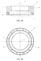
- a groove depth of the annular groove 24 in the upper housing 20 is set to be greater than the plate thickness of the upper end portion 71C and lower end portion 71D of the first magnetism collecting ring 71. Therefore, when the first magnetism collecting ring 71 is fitted into the annular groove 24, respective inner peripheral surfaces of the upper end portion 71C and the lower end portion 71D of the first magnetism collecting ring 71 are set back from the inner peripheral wall of the upper housing 20 toward the annular groove 24 side, while an inner peripheral surface of the central portion 71B of the first magnetism collecting ring 71 is flush with the inner peripheral wall of the upper housing 20.
- the inner peripheral surface of the central portion 71B faces an outer peripheral surface of the first magnetic path ring portion 61C of the first soft magnetic ring 61 via a predetermined gap.
- the first magnetism collecting ring 71 fitted into the annular groove 24 is caulked to the upper housing 20 by caulk portions 25 formed on the inner peripheral wall of the upper housing 20.
- Six caulk portions 25 are formed in the circumferential direction on the inner peripheral wall of the upper housing 20 on a lower side of the annular groove 24. In this embodiment, six caulk portions 25 are formed, but the number of caulk portions 25 may be set as desired according to necessity.
- the caulk portions 25 are formed to cover the lower end portion 71D of the first magnetism collecting ring 71 by driving a caulking tool into the inner peripheral wall of the upper housing 20 in a position of an arrow in FIG. 6B so as to deform a part of the inner peripheral wall of the upper housing 20.
- the first magnetism collecting ring 71 Since the first magnetism collecting ring 71 is caulked to the upper housing 20 by the six caulk portions 25 in this manner, the first magnetism collecting ring 71 does not rattle or rotate within the annular groove 24.
- the caulk portions 25 latch a lower side of the inner peripheral surface of the first magnetism collecting ring 71, thereby restricting movement of the first magnetism collecting ring 71 in the radial direction, and as a result, the first magnetism collecting ring 71 can be prevented from disengaging from the annular groove 24.
- the caulk portions 25 are formed to cover the thin lower end portion 71D of the first magnetism collecting ring 71, and do not therefore project further inward than the inner peripheral wall of the upper housing 20. Furthermore, in a caulked condition, the inner peripheral surface of the central portion 71B of the first magnetism collecting ring 71 is flush with the inner peripheral wall of the upper housing 20. In other words, the inner peripheral surface of the central portion 71B and the inner peripheral wall of the upper housing 20 are positioned on an identical cylindrical surface.
- the inner peripheral surface of the central portion 71B of the first magnetism collecting ring 71 may be set to be substantially flush with the inner peripheral wall of the upper housing 20.
- the inner peripheral surface of the central portion 71B may be set to be slightly higher or slightly lower than the inner peripheral wall of the upper housing 20 as long as a collision between the constituent members of the rotary magnetic circuit portion 60 and the first magnetism collecting ring 71 and caulk portions 25 is prevented.
- the caulk portions 25 are formed in positions below the annular groove 24 into which the first magnetism collecting ring 71 is fitted, but the formation positions of the caulk portions 25 are not limited thereto.
- caulk portions 25 covering the upper end portion 7 1C of the first magnetism collecting ring 71 may be formed in addition to the caulk portions 25 covering the lower end portion 71D of the first magnetism collecting ring 71.
- the first magnetism collecting ring 71 can be caulked to the upper housing 20 even more securely.
- the first magnetism collecting ring 71 may also be caulked to the upper housing 20 using only the caulk portions 25 covering the upper end portion 71C of the first magnetism collecting ring 71.
- the second magnetism collecting ring 72 is configured identically to the first magnetism collecting ring 71.
- a radial direction plate thickness of an upper end portion 72C and a lower end portion 72D of the second magnetism collecting ring 72 is set to be thinner than a plate thickness of a central portion 72B.
- the second magnetism collecting ring 72 is fitted into the annular groove 24 positioned below the first magnetism collecting ring 71, whereupon the second magnetism collecting ring 72, similarly to the first magnetism collecting ring 71, is caulked to the upper housing 20 by the caulk portions 25 formed in the inner peripheral wall of the upper housing 20.
- the second magnetism collecting ring 72 is caulked identically to the first magnetism collecting ring 71, and therefore description of the manner in which the second magnetism collecting ring 72 is caulked has been omitted.
- the first magnetism collecting ring 71 and the second magnetism collecting ring 72 are caulked to the upper housing 20. Therefore the first magnetism collecting ring 71 and the second magnetism collecting ring 72 can be prevented from disengaging from the respective annular grooves 24. As a result, the first magnetism collecting ring 71 and the second magnetism collecting ring 72 are caulked to the upper housing 20 more securely.
- the first magnetism collecting ring 71 and the second magnetism collecting ring 72 do not project further inward than the inner peripheral wall of the upper housing 20. Therefore, interference between the constituent members of the rotary magnetic circuit portion 60 and the first and second magnetism collecting rings 71, 72 can be prevented when the output shaft 13, to which the rotary magnetic circuit portion 60 is fixed, is inserted into the upper housing 20. As a result, workability during assembly of the torque sensor 40 can be improved.
- FIG. 8 is a partial longitudinal sectional view showing the upper housing 20 of the torque sensor 40 according to the second embodiment.
- the second embodiment will be described focusing on parts that differ from the first embodiment. It should be noted that in FIG. 8 , identical constituent parts to the first embodiment have been allocated identical reference symbols to the first embodiment.
- upper and lower caulking promotion grooves 26 are formed in series with the annular groove 24 in the axial direction as recesses in the inner peripheral wall of the upper housing 20.
- the upper and lower caulking promotion grooves 26 are formed in a ring shape in series with the annular groove 24 in the axial direction and at a predetermined distance (between 0.5 and 1.0mm, for example) therefrom.
- the caulking promotion grooves 26 are formed as slits having a rectangular longitudinal section.
- annular caulking wall portions 27 are formed in the upper housing 20 between the annular groove 24 and the respective caulking promotion grooves 26.
- the caulking wall portions 27 are formed as ribs having a rectangular longitudinal section.
- the first magnetism collecting ring 71 is fitted into the annular groove 24.
- respective tip end portions (inner peripheral end portions) of the caulking wall portion 27 are deformed by being bent so as to tilt toward the first magnetism collecting ring 71 by driving a caulking tool into the caulking promotion grooves 26, thereby forming hook-shaped caulk portions 28 respectively covering the upper end portion 71C and the lower end portion 71D of the first magnetism collecting ring 71.
- the caulk portions 25 are formed by driving a caulking tool into the inner peripheral wall of the upper housing 20 such that the inner peripheral wall of the upper housing 20 is partially lifted.
- the caulk portions 25 are formed in this manner, it is difficult to increase a thickness of sites that are lifted onto the upper end portion 71C and the lower end portion 71D of the first magnetism collecting ring 71.
- the caulking promotion grooves 26 formed adjacent to the annular groove 24 and the caulking wall portions 27 remaining between the annular groove 24 and the respective caulking promotion grooves 26 are formed in the inner peripheral wall of the upper housing 20.
- the caulk portions 28 are then formed by pressing a caulking tool against the caulking promotion grooves 26 so as to bend the caulking wall portions 27.
- the thickness of the sites that are lifted onto the upper end portion 71C and the lower end portion 71D of the first magnetism collecting ring 71 can be increased in comparison with the caulk portions 25 of the first embodiment.
- the caulk portions 28 are formed by deforming the caulking wall portions 27, and therefore irregularities in a shape of the caulk portions 28 can be suppressed, enabling an improvement in quality.
- caulk portions 28 are formed at predetermined intervals in the circumferential direction, but the number of caulk portions 28 may be set as desired according to necessity. It should be noted that the caulk portions 28 that are lifted onto the upper end portion 71C and the lower end portion 71D of the first magnetism collecting ring 71 may be formed in an annular shape by pressing a roller-shaped caulking tool over an entire periphery of the caulking promotion grooves 26.
- caulking promotion grooves 26 are not limited to being formed in an annular shape, and may be provided as recessed portions formed in a plurality of locations positioned in the vicinity of the caulk portions 28.
- the present invention is not limited to a configuration in which the upper and lower caulk portions 28 are respectively formed to cover the upper end portion 71C and the lower end portion 71D of the first magnetism collecting ring 71, and instead, the first magnetism collecting ring 71 may be caulked to the upper housing 20 by forming only one of the upper and lower caulk portions 28.
- FIG. 8 illustrates caulking of the first magnetism collecting ring 71, but the second magnetism collecting ring 72 is caulked identically to the first magnetism collecting ring 71, and therefore description of the manner in which the second magnetism collecting ring 72 is caulked has been omitted.
- the first magnetism collecting ring 71 and the second magnetism collecting ring 72 are fixed to the upper housing 20 by the caulk portions 25, 28, which are formed by thermal welding-type caulking.
Landscapes
- Physics & Mathematics (AREA)
- Electromagnetism (AREA)
- General Physics & Mathematics (AREA)
- Power Steering Mechanism (AREA)
- Force Measurement Appropriate To Specific Purposes (AREA)
Applications Claiming Priority (3)
| Application Number | Priority Date | Filing Date | Title |
|---|---|---|---|
| JP2011060228 | 2011-03-18 | ||
| JP2011193793A JP5756376B2 (ja) | 2011-03-18 | 2011-09-06 | トルクセンサ |
| PCT/JP2012/056007 WO2012128060A1 (ja) | 2011-03-18 | 2012-03-08 | トルクセンサ |
Publications (3)
| Publication Number | Publication Date |
|---|---|
| EP2687833A1 true EP2687833A1 (de) | 2014-01-22 |
| EP2687833A4 EP2687833A4 (de) | 2014-10-08 |
| EP2687833B1 EP2687833B1 (de) | 2016-09-28 |
Family
ID=46879214
Family Applications (1)
| Application Number | Title | Priority Date | Filing Date |
|---|---|---|---|
| EP12760559.0A Active EP2687833B1 (de) | 2011-03-18 | 2012-03-08 | Drehmomentsensor |
Country Status (6)
| Country | Link |
|---|---|
| US (1) | US9116059B2 (de) |
| EP (1) | EP2687833B1 (de) |
| JP (1) | JP5756376B2 (de) |
| CN (1) | CN103429999B (de) |
| ES (1) | ES2600078T3 (de) |
| WO (1) | WO2012128060A1 (de) |
Families Citing this family (6)
| Publication number | Priority date | Publication date | Assignee | Title |
|---|---|---|---|---|
| JP5843100B2 (ja) * | 2011-11-08 | 2016-01-13 | 株式会社ジェイテクト | トルク検出装置および電動パワーステアリング装置 |
| JP2016160995A (ja) * | 2015-02-27 | 2016-09-05 | 大豊工業株式会社 | 軸受装置 |
| FR3047560B1 (fr) * | 2016-02-10 | 2018-03-16 | Jtekt Europe | Procede de fabrication d’un capteur de couple comprenant une etape d’encapsulation du circuit electronique du capteur. |
| EP3354860B1 (de) * | 2017-01-30 | 2020-05-06 | Ge Avio S.r.l. | Magnetisches drehmomentmesssystem |
| KR102106294B1 (ko) * | 2018-09-21 | 2020-05-04 | 주식회사 만도 | 자동차 조향장치 |
| CN111256897A (zh) * | 2018-11-30 | 2020-06-09 | 长城汽车股份有限公司 | 扭矩传感器以及车辆 |
Family Cites Families (13)
| Publication number | Priority date | Publication date | Assignee | Title |
|---|---|---|---|---|
| JPH08270614A (ja) * | 1995-03-30 | 1996-10-15 | Matsui Seisakusho:Kk | 流体圧アクチュエータ |
| EP1043570A3 (de) * | 1999-04-08 | 2004-06-23 | Alps Electric Co., Ltd. | Winkelsensor |
| FR2824910B1 (fr) * | 2001-05-18 | 2005-05-13 | Denso Corp | Capteur de couple et systeme de direction assistee electrique employant ce capteur |
| JP4190849B2 (ja) * | 2002-10-07 | 2008-12-03 | 株式会社日本自動車部品総合研究所 | トルクセンサ |
| JP2005121507A (ja) * | 2003-10-17 | 2005-05-12 | Hitachi Ltd | トルクセンサ |
| JP2007040789A (ja) * | 2005-08-02 | 2007-02-15 | Jtekt Corp | トルク検出装置 |
| JP4871014B2 (ja) * | 2006-04-24 | 2012-02-08 | カヤバ工業株式会社 | トルクセンサ |
| CN201177540Y (zh) * | 2008-03-14 | 2009-01-07 | 佛山市恒威汽车动力转向器有限公司 | 非接触式转矩传感器 |
| JP5191774B2 (ja) * | 2008-03-31 | 2013-05-08 | カヤバ工業株式会社 | トルクセンサ及びその製造方法 |
| JP5130097B2 (ja) * | 2008-03-31 | 2013-01-30 | カヤバ工業株式会社 | トルクセンサ |
| US8847522B2 (en) * | 2008-11-14 | 2014-09-30 | Denso Corporation | Reluctance motor with improved stator structure |
| JP2011013133A (ja) * | 2009-07-03 | 2011-01-20 | Kyb Co Ltd | トルクセンサ |
| JP5513902B2 (ja) * | 2010-01-12 | 2014-06-04 | カヤバ工業株式会社 | トルクセンサ |
-
2011
- 2011-09-06 JP JP2011193793A patent/JP5756376B2/ja active Active
-
2012
- 2012-03-08 ES ES12760559.0T patent/ES2600078T3/es active Active
- 2012-03-08 EP EP12760559.0A patent/EP2687833B1/de active Active
- 2012-03-08 CN CN201280013300.2A patent/CN103429999B/zh active Active
- 2012-03-08 US US14/005,649 patent/US9116059B2/en active Active
- 2012-03-08 WO PCT/JP2012/056007 patent/WO2012128060A1/ja not_active Ceased
Also Published As
| Publication number | Publication date |
|---|---|
| US20140007701A1 (en) | 2014-01-09 |
| EP2687833A4 (de) | 2014-10-08 |
| JP5756376B2 (ja) | 2015-07-29 |
| CN103429999A (zh) | 2013-12-04 |
| ES2600078T3 (es) | 2017-02-07 |
| US9116059B2 (en) | 2015-08-25 |
| JP2012211887A (ja) | 2012-11-01 |
| WO2012128060A1 (ja) | 2012-09-27 |
| EP2687833B1 (de) | 2016-09-28 |
| CN103429999B (zh) | 2015-03-25 |
Similar Documents
| Publication | Publication Date | Title |
|---|---|---|
| EP2687833B1 (de) | Drehmomentsensor | |
| JP5191774B2 (ja) | トルクセンサ及びその製造方法 | |
| JP5130097B2 (ja) | トルクセンサ | |
| EP2343527B1 (de) | Drehmomentsensor | |
| US20110000319A1 (en) | Torque sensor | |
| EP2832626B1 (de) | Elektrische servolenkvorrichtung | |
| JP5153490B2 (ja) | トルクセンサ | |
| JP2010091316A (ja) | トルクセンサ | |
| JP2011013134A (ja) | トルクセンサ | |
| US9945742B2 (en) | Torque sensor and electric power steering apparatus | |
| JP2012194143A (ja) | トルクセンサ | |
| JP2012194144A (ja) | トルクセンサ | |
| JP5031672B2 (ja) | トルクセンサの組立方法 | |
| JP2006329685A (ja) | トルクセンサ | |
| WO2012128059A1 (ja) | トルクセンサ | |
| JP2013029357A (ja) | パワーステアリング装置 |
Legal Events
| Date | Code | Title | Description |
|---|---|---|---|
| PUAI | Public reference made under article 153(3) epc to a published international application that has entered the european phase |
Free format text: ORIGINAL CODE: 0009012 |
|
| 17P | Request for examination filed |
Effective date: 20131017 |
|
| AK | Designated contracting states |
Kind code of ref document: A1 Designated state(s): AL AT BE BG CH CY CZ DE DK EE ES FI FR GB GR HR HU IE IS IT LI LT LU LV MC MK MT NL NO PL PT RO RS SE SI SK SM TR |
|
| DAX | Request for extension of the european patent (deleted) | ||
| A4 | Supplementary search report drawn up and despatched |
Effective date: 20140904 |
|
| RIC1 | Information provided on ipc code assigned before grant |
Ipc: G01L 3/10 20060101AFI20140829BHEP |
|
| RAP1 | Party data changed (applicant data changed or rights of an application transferred) |
Owner name: KYB CORPORATION |
|
| GRAP | Despatch of communication of intention to grant a patent |
Free format text: ORIGINAL CODE: EPIDOSNIGR1 |
|
| INTG | Intention to grant announced |
Effective date: 20160504 |
|
| GRAS | Grant fee paid |
Free format text: ORIGINAL CODE: EPIDOSNIGR3 |
|
| GRAA | (expected) grant |
Free format text: ORIGINAL CODE: 0009210 |
|
| RIN1 | Information on inventor provided before grant (corrected) |
Inventor name: YAGYU, TAKAYA Inventor name: MAEHARA, HIDEO |
|
| AK | Designated contracting states |
Kind code of ref document: B1 Designated state(s): AL AT BE BG CH CY CZ DE DK EE ES FI FR GB GR HR HU IE IS IT LI LT LU LV MC MK MT NL NO PL PT RO RS SE SI SK SM TR |
|
| REG | Reference to a national code |
Ref country code: GB Ref legal event code: FG4D |
|
| REG | Reference to a national code |
Ref country code: CH Ref legal event code: EP |
|
| REG | Reference to a national code |
Ref country code: AT Ref legal event code: REF Ref document number: 833175 Country of ref document: AT Kind code of ref document: T Effective date: 20161015 |
|
| REG | Reference to a national code |
Ref country code: IE Ref legal event code: FG4D |
|
| REG | Reference to a national code |
Ref country code: DE Ref legal event code: R096 Ref document number: 602012023544 Country of ref document: DE |
|
| REG | Reference to a national code |
Ref country code: LT Ref legal event code: MG4D |
|
| PG25 | Lapsed in a contracting state [announced via postgrant information from national office to epo] |
Ref country code: NO Free format text: LAPSE BECAUSE OF FAILURE TO SUBMIT A TRANSLATION OF THE DESCRIPTION OR TO PAY THE FEE WITHIN THE PRESCRIBED TIME-LIMIT Effective date: 20161228 Ref country code: RS Free format text: LAPSE BECAUSE OF FAILURE TO SUBMIT A TRANSLATION OF THE DESCRIPTION OR TO PAY THE FEE WITHIN THE PRESCRIBED TIME-LIMIT Effective date: 20160928 Ref country code: HR Free format text: LAPSE BECAUSE OF FAILURE TO SUBMIT A TRANSLATION OF THE DESCRIPTION OR TO PAY THE FEE WITHIN THE PRESCRIBED TIME-LIMIT Effective date: 20160928 Ref country code: LT Free format text: LAPSE BECAUSE OF FAILURE TO SUBMIT A TRANSLATION OF THE DESCRIPTION OR TO PAY THE FEE WITHIN THE PRESCRIBED TIME-LIMIT Effective date: 20160928 Ref country code: FI Free format text: LAPSE BECAUSE OF FAILURE TO SUBMIT A TRANSLATION OF THE DESCRIPTION OR TO PAY THE FEE WITHIN THE PRESCRIBED TIME-LIMIT Effective date: 20160928 |
|
| REG | Reference to a national code |
Ref country code: NL Ref legal event code: MP Effective date: 20160928 |
|
| REG | Reference to a national code |
Ref country code: ES Ref legal event code: FG2A Ref document number: 2600078 Country of ref document: ES Kind code of ref document: T3 Effective date: 20170207 |
|
| REG | Reference to a national code |
Ref country code: AT Ref legal event code: MK05 Ref document number: 833175 Country of ref document: AT Kind code of ref document: T Effective date: 20160928 |
|
| PG25 | Lapsed in a contracting state [announced via postgrant information from national office to epo] |
Ref country code: GR Free format text: LAPSE BECAUSE OF FAILURE TO SUBMIT A TRANSLATION OF THE DESCRIPTION OR TO PAY THE FEE WITHIN THE PRESCRIBED TIME-LIMIT Effective date: 20161229 Ref country code: SE Free format text: LAPSE BECAUSE OF FAILURE TO SUBMIT A TRANSLATION OF THE DESCRIPTION OR TO PAY THE FEE WITHIN THE PRESCRIBED TIME-LIMIT Effective date: 20160928 Ref country code: LV Free format text: LAPSE BECAUSE OF FAILURE TO SUBMIT A TRANSLATION OF THE DESCRIPTION OR TO PAY THE FEE WITHIN THE PRESCRIBED TIME-LIMIT Effective date: 20160928 Ref country code: NL Free format text: LAPSE BECAUSE OF FAILURE TO SUBMIT A TRANSLATION OF THE DESCRIPTION OR TO PAY THE FEE WITHIN THE PRESCRIBED TIME-LIMIT Effective date: 20160928 |
|
| REG | Reference to a national code |
Ref country code: FR Ref legal event code: PLFP Year of fee payment: 6 |
|
| PG25 | Lapsed in a contracting state [announced via postgrant information from national office to epo] |
Ref country code: EE Free format text: LAPSE BECAUSE OF FAILURE TO SUBMIT A TRANSLATION OF THE DESCRIPTION OR TO PAY THE FEE WITHIN THE PRESCRIBED TIME-LIMIT Effective date: 20160928 Ref country code: RO Free format text: LAPSE BECAUSE OF FAILURE TO SUBMIT A TRANSLATION OF THE DESCRIPTION OR TO PAY THE FEE WITHIN THE PRESCRIBED TIME-LIMIT Effective date: 20160928 |
|
| PG25 | Lapsed in a contracting state [announced via postgrant information from national office to epo] |
Ref country code: BG Free format text: LAPSE BECAUSE OF FAILURE TO SUBMIT A TRANSLATION OF THE DESCRIPTION OR TO PAY THE FEE WITHIN THE PRESCRIBED TIME-LIMIT Effective date: 20161228 Ref country code: CZ Free format text: LAPSE BECAUSE OF FAILURE TO SUBMIT A TRANSLATION OF THE DESCRIPTION OR TO PAY THE FEE WITHIN THE PRESCRIBED TIME-LIMIT Effective date: 20160928 Ref country code: AT Free format text: LAPSE BECAUSE OF FAILURE TO SUBMIT A TRANSLATION OF THE DESCRIPTION OR TO PAY THE FEE WITHIN THE PRESCRIBED TIME-LIMIT Effective date: 20160928 Ref country code: SM Free format text: LAPSE BECAUSE OF FAILURE TO SUBMIT A TRANSLATION OF THE DESCRIPTION OR TO PAY THE FEE WITHIN THE PRESCRIBED TIME-LIMIT Effective date: 20160928 Ref country code: PT Free format text: LAPSE BECAUSE OF FAILURE TO SUBMIT A TRANSLATION OF THE DESCRIPTION OR TO PAY THE FEE WITHIN THE PRESCRIBED TIME-LIMIT Effective date: 20170130 Ref country code: BE Free format text: LAPSE BECAUSE OF FAILURE TO SUBMIT A TRANSLATION OF THE DESCRIPTION OR TO PAY THE FEE WITHIN THE PRESCRIBED TIME-LIMIT Effective date: 20160928 Ref country code: SK Free format text: LAPSE BECAUSE OF FAILURE TO SUBMIT A TRANSLATION OF THE DESCRIPTION OR TO PAY THE FEE WITHIN THE PRESCRIBED TIME-LIMIT Effective date: 20160928 Ref country code: IS Free format text: LAPSE BECAUSE OF FAILURE TO SUBMIT A TRANSLATION OF THE DESCRIPTION OR TO PAY THE FEE WITHIN THE PRESCRIBED TIME-LIMIT Effective date: 20170128 Ref country code: PL Free format text: LAPSE BECAUSE OF FAILURE TO SUBMIT A TRANSLATION OF THE DESCRIPTION OR TO PAY THE FEE WITHIN THE PRESCRIBED TIME-LIMIT Effective date: 20160928 |
|
| REG | Reference to a national code |
Ref country code: DE Ref legal event code: R097 Ref document number: 602012023544 Country of ref document: DE |
|
| PG25 | Lapsed in a contracting state [announced via postgrant information from national office to epo] |
Ref country code: IT Free format text: LAPSE BECAUSE OF FAILURE TO SUBMIT A TRANSLATION OF THE DESCRIPTION OR TO PAY THE FEE WITHIN THE PRESCRIBED TIME-LIMIT Effective date: 20160928 |
|
| PG25 | Lapsed in a contracting state [announced via postgrant information from national office to epo] |
Ref country code: DK Free format text: LAPSE BECAUSE OF FAILURE TO SUBMIT A TRANSLATION OF THE DESCRIPTION OR TO PAY THE FEE WITHIN THE PRESCRIBED TIME-LIMIT Effective date: 20160928 |
|
| PLBE | No opposition filed within time limit |
Free format text: ORIGINAL CODE: 0009261 |
|
| STAA | Information on the status of an ep patent application or granted ep patent |
Free format text: STATUS: NO OPPOSITION FILED WITHIN TIME LIMIT |
|
| 26N | No opposition filed |
Effective date: 20170629 |
|
| REG | Reference to a national code |
Ref country code: CH Ref legal event code: PL |
|
| PG25 | Lapsed in a contracting state [announced via postgrant information from national office to epo] |
Ref country code: MC Free format text: LAPSE BECAUSE OF FAILURE TO SUBMIT A TRANSLATION OF THE DESCRIPTION OR TO PAY THE FEE WITHIN THE PRESCRIBED TIME-LIMIT Effective date: 20160928 Ref country code: SI Free format text: LAPSE BECAUSE OF FAILURE TO SUBMIT A TRANSLATION OF THE DESCRIPTION OR TO PAY THE FEE WITHIN THE PRESCRIBED TIME-LIMIT Effective date: 20160928 |
|
| REG | Reference to a national code |
Ref country code: IE Ref legal event code: MM4A |
|
| PG25 | Lapsed in a contracting state [announced via postgrant information from national office to epo] |
Ref country code: LU Free format text: LAPSE BECAUSE OF NON-PAYMENT OF DUE FEES Effective date: 20170308 |
|
| PG25 | Lapsed in a contracting state [announced via postgrant information from national office to epo] |
Ref country code: LI Free format text: LAPSE BECAUSE OF NON-PAYMENT OF DUE FEES Effective date: 20170331 Ref country code: CH Free format text: LAPSE BECAUSE OF NON-PAYMENT OF DUE FEES Effective date: 20170331 Ref country code: IE Free format text: LAPSE BECAUSE OF NON-PAYMENT OF DUE FEES Effective date: 20170308 |
|
| REG | Reference to a national code |
Ref country code: FR Ref legal event code: PLFP Year of fee payment: 7 |
|
| PGFP | Annual fee paid to national office [announced via postgrant information from national office to epo] |
Ref country code: GB Payment date: 20180321 Year of fee payment: 7 |
|
| PGFP | Annual fee paid to national office [announced via postgrant information from national office to epo] |
Ref country code: ES Payment date: 20180430 Year of fee payment: 7 |
|
| PG25 | Lapsed in a contracting state [announced via postgrant information from national office to epo] |
Ref country code: MT Free format text: LAPSE BECAUSE OF NON-PAYMENT OF DUE FEES Effective date: 20170308 |
|
| PG25 | Lapsed in a contracting state [announced via postgrant information from national office to epo] |
Ref country code: AL Free format text: LAPSE BECAUSE OF FAILURE TO SUBMIT A TRANSLATION OF THE DESCRIPTION OR TO PAY THE FEE WITHIN THE PRESCRIBED TIME-LIMIT Effective date: 20160928 |
|
| PGFP | Annual fee paid to national office [announced via postgrant information from national office to epo] |
Ref country code: IT Payment date: 20190121 Year of fee payment: 8 |
|
| PG25 | Lapsed in a contracting state [announced via postgrant information from national office to epo] |
Ref country code: HU Free format text: LAPSE BECAUSE OF FAILURE TO SUBMIT A TRANSLATION OF THE DESCRIPTION OR TO PAY THE FEE WITHIN THE PRESCRIBED TIME-LIMIT; INVALID AB INITIO Effective date: 20120308 |
|
| PG25 | Lapsed in a contracting state [announced via postgrant information from national office to epo] |
Ref country code: CY Free format text: LAPSE BECAUSE OF NON-PAYMENT OF DUE FEES Effective date: 20160928 |
|
| GBPC | Gb: european patent ceased through non-payment of renewal fee |
Effective date: 20190308 |
|
| PG25 | Lapsed in a contracting state [announced via postgrant information from national office to epo] |
Ref country code: MK Free format text: LAPSE BECAUSE OF FAILURE TO SUBMIT A TRANSLATION OF THE DESCRIPTION OR TO PAY THE FEE WITHIN THE PRESCRIBED TIME-LIMIT Effective date: 20160928 |
|
| PG25 | Lapsed in a contracting state [announced via postgrant information from national office to epo] |
Ref country code: GB Free format text: LAPSE BECAUSE OF NON-PAYMENT OF DUE FEES Effective date: 20190308 |
|
| PG25 | Lapsed in a contracting state [announced via postgrant information from national office to epo] |
Ref country code: TR Free format text: LAPSE BECAUSE OF FAILURE TO SUBMIT A TRANSLATION OF THE DESCRIPTION OR TO PAY THE FEE WITHIN THE PRESCRIBED TIME-LIMIT Effective date: 20160928 |
|
| REG | Reference to a national code |
Ref country code: ES Ref legal event code: FD2A Effective date: 20200724 |
|
| PG25 | Lapsed in a contracting state [announced via postgrant information from national office to epo] |
Ref country code: ES Free format text: LAPSE BECAUSE OF NON-PAYMENT OF DUE FEES Effective date: 20190309 |
|
| PG25 | Lapsed in a contracting state [announced via postgrant information from national office to epo] |
Ref country code: FR Free format text: LAPSE BECAUSE OF NON-PAYMENT OF DUE FEES Effective date: 20200331 |
|
| PGFP | Annual fee paid to national office [announced via postgrant information from national office to epo] |
Ref country code: DE Payment date: 20260319 Year of fee payment: 15 |