EP2687924A2 - Machine agricole automobile - Google Patents
Machine agricole automobile Download PDFInfo
- Publication number
- EP2687924A2 EP2687924A2 EP13172057.5A EP13172057A EP2687924A2 EP 2687924 A2 EP2687924 A2 EP 2687924A2 EP 13172057 A EP13172057 A EP 13172057A EP 2687924 A2 EP2687924 A2 EP 2687924A2
- Authority
- EP
- European Patent Office
- Prior art keywords
- control
- working
- self
- agricultural
- regulating device
- Prior art date
- Legal status (The legal status is an assumption and is not a legal conclusion. Google has not performed a legal analysis and makes no representation as to the accuracy of the status listed.)
- Granted
Links
Images


Classifications
-
- A—HUMAN NECESSITIES
- A01—AGRICULTURE; FORESTRY; ANIMAL HUSBANDRY; HUNTING; TRAPPING; FISHING
- A01D—HARVESTING; MOWING
- A01D41/00—Combines, i.e. harvesters or mowers combined with threshing devices
- A01D41/12—Details of combines
- A01D41/127—Control or measuring arrangements specially adapted for combines
- A01D41/1274—Control or measuring arrangements specially adapted for combines for drives
-
- G—PHYSICS
- G05—CONTROLLING; REGULATING
- G05B—CONTROL OR REGULATING SYSTEMS IN GENERAL; FUNCTIONAL ELEMENTS OF SUCH SYSTEMS; MONITORING OR TESTING ARRANGEMENTS FOR SUCH SYSTEMS OR ELEMENTS
- G05B13/00—Adaptive control systems, i.e. systems automatically adjusting themselves to have a performance which is optimum according to some preassigned criterion
- G05B13/02—Adaptive control systems, i.e. systems automatically adjusting themselves to have a performance which is optimum according to some preassigned criterion electric
- G05B13/0205—Adaptive control systems, i.e. systems automatically adjusting themselves to have a performance which is optimum according to some preassigned criterion electric not using a model or a simulator of the controlled system
- G05B13/021—Adaptive control systems, i.e. systems automatically adjusting themselves to have a performance which is optimum according to some preassigned criterion electric not using a model or a simulator of the controlled system in which a variable is automatically adjusted to optimise the performance
-
- G—PHYSICS
- G05—CONTROLLING; REGULATING
- G05B—CONTROL OR REGULATING SYSTEMS IN GENERAL; FUNCTIONAL ELEMENTS OF SUCH SYSTEMS; MONITORING OR TESTING ARRANGEMENTS FOR SUCH SYSTEMS OR ELEMENTS
- G05B2219/00—Program-control systems
- G05B2219/30—Nc systems
- G05B2219/45—Nc applications
- G05B2219/45017—Agriculture machine, tractor
-
- G—PHYSICS
- G05—CONTROLLING; REGULATING
- G05B—CONTROL OR REGULATING SYSTEMS IN GENERAL; FUNCTIONAL ELEMENTS OF SUCH SYSTEMS; MONITORING OR TESTING ARRANGEMENTS FOR SUCH SYSTEMS OR ELEMENTS
- G05B2219/00—Program-control systems
- G05B2219/30—Nc systems
- G05B2219/45—Nc applications
- G05B2219/45106—Used in agriculture, tree trimmer, pruner
Definitions
- the present invention relates to a self-propelled agricultural machine with work organs whose working parameters are automatically adjustable by at least one control and regulating device according to the preamble of claim 1.
- Object of the present invention is therefore to further develop the control and regulating device of an agricultural machine such that a high-quality control of the agricultural machine is possible.
- control and regulating device of a self-propelled agricultural work machine includes a process coordinator, which evaluates at least one common parameter of the respective work organs, and at least for this parameter determines a value at which at least the monitored by the control and regulating devices working optimally and this determined Value of the at least one common parameter is used as a reference variable of the control and regulating device ensures that the agricultural machine can be operated in total in its most optimal operating point.
- a particularly efficient operating point optimization of the agricultural working machine results when the maximum workable throughput and / or the maximum workable layer height of the respective working organs is evaluated as a parameter.
- a particularly efficiently operating control loop results in an advantageous embodiment of the invention when the process coordinator determines the optimized value from the maximum workable throughput determined for the respective working element or the maximum workable layer height and defines this as the reference variable for the control and regulating device.
- the optimized value corresponds to the lowest of the determined maximum throughputs or layer heights.
- the quality of the optimization result can be further increased if the control and regulating device in addition to working parameters and quality parameters of the agricultural machine monitors and regulates and wherein the regulation of the work and quality parameters of one or more working bodies is stored in automatic teller.
- the control and regulating device in addition to working parameters and quality parameters of the agricultural machine monitors and regulates and wherein the regulation of the work and quality parameters of one or more working bodies is stored in automatic teller.
- a particularly effective influence on an efficient operation of the agricultural machine is achieved in this context, when the setting machines include at least a cleaning machine and an automatic separator.
- a driving speed controller which predefines the driving speed and determining a driving speed of the agricultural machine from the characteristic curves stored in the driving speed controller, it is ensured in a simple manner that none of the working members is overloaded.
- a particularly efficiently operating control loop results when, in an advantageous embodiment of the invention, the working and / or quality parameters of the agricultural machine are monitored and controlled in a continuously operating control loop by means of the setting machines and the process coordinator in the same control loop continuously an optimized value of Good throughput and / or the layer height as a reference variable of the control to the cruise control and the Einstellautomaten passes and they also generate continuously in response to this command variable a vehicle speed signal for adjusting the driving speed of the agricultural machine and optimized values of the working parameters.
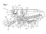
- a combine harvester 2 running agricultural machine 1 takes in its front area on a grain cutting unit 3, which is connected in a conventional manner with the inclined conveyor 4 of the combine harvester 2.
- the crop feed stream 5 passing through the inclined conveyor 4 is transferred to the threshing elements 7 of the combine harvester 2, which are at least partly covered by a so-called threshing basket 6 at the bottom, at the rear, of the inclined conveyor 4.
- a deflecting drum 8 arranged downstream of the threshing members 7 deflects the crop stream 5 emerging from the threshing members 7 in the rear region such that it is transferred directly to a separating device 10 designed as a separating rotor 9.
- the material flow 5 is conveyed so that free-moving grains 11 contained in the material flow 5 are deposited in the lower-side region of the separation rotor 9.
- the separating device 10 embodied as a separating rotor 9 in the illustrated embodiment can also be embodied as a horden shaker known per se and therefore not shown.
- Both the grains 11 deposited on concave 6 and separating rotor 9 are fed via return bottom 12 and feed bottom 13 to a cleaning device 17 consisting of a plurality of screen planes 14, 15 and a fan 16.
- the cleaned grain stream is finally transferred by elevators 18 to a grain tank 19.
- the agricultural work machine 1 has a vehicle cabin 21 in which at least one control unit 23 provided with a display unit 22 is arranged, by means of which automatically or by the operator 24 of the agricultural work machine 1 initiates a multiplicity of per se known and therefore unspecified Processes can be controlled.
- the control and regulating device 23 communicates via a so-called bus system 25 in a manner known per se with a plurality of sensor systems 26. Details regarding the structure of the sensor systems 26 are described in detail in FIGS DE 101 47 733 described, the content of which is hereby fully part of the disclosure of this patent application, so that the structure of the sensor systems 26 will not be described again in the following.
- the control and regulating device 23 is coupled to a driver assistance system 28 comprising a display unit 27.
- driver assistance system 28 may also be integrated directly into the control and regulating device 23 and the visualization of the provided by the driver assistance system 28 and explained in more detail below information 29 also directly in the control and regulating device 23 assigned Display unit 22 takes place.
- Fig. 2 2 shows a schematic representation of the display unit 22 of the control and regulation device 23 as well as the arithmetic unit 30 associated with the control and regulating device 23 and coupled to the display unit 22.
- the arithmetic unit 30 is designed such that, in addition to the internal information 31 generated by the sensor systems 26 , external information 32 and in the computing unit 30 self-stored information 33, such as expert knowledge, to process a plurality of output signals 34.
- the output signals 34 are designed to comprise at least display control signals 35 and work control signals 36, the former determining the contents of the display unit 22 and causing the change of the various working parameters 37 of the working members 20 of the agricultural machine 1, wherein arrow 37 is symbolic of the threshing drum speed stands.
- control and regulating device 23 as already described, with coupled to a driver assistance system 28, wherein the driver assistance system 28 is integrated into the agricultural machine 1 so that it can exchange data 38 in a manner to be described in more detail both with the control and regulating device 23 and with the associated display unit 22.
- FIG. 2 shown contents of the display units 22, 27 are exemplary and will be described in more detail below.
- the control unit 23 associated display unit 22 includes in its central area by the operator 24 a freely definable so-called hotkey window 38 in which important machine information, such as the level of the fuel tank 38 a, machine parameter settings 38 b and the travel speed 38 c are visualized.
- the display unit 22 comprises in its right-hand side display elements 39 for visualizing current values of certain quality parameters 40 of the agricultural machine 1.
- the display unit 39 arranged on the top visualizes the composition of the so-called “tailings” 41, wherein the left-hand representation the “tailings volume” 41 a and the right-hand representation of the "grain fraction in the tailings” 41 b visualized.
- the lower, left display element 39 visualizes the so-called “deposition losses” 42, i. those grain losses, which are discharged from the separating device 10 designed as a separating rotor 9 or Horden presentler in the rear region of the agricultural machine 1 from this and not promoted in the grain tank 19.
- the lower right display element 39 visualizes the so-called "cleaning losses" 43, in which case those grain losses are displayed, which are discharged by the cleaning device 17 in an analogous manner to the separating device 10 from the agricultural machine 1 and not conveyed into the grain tank 19.
- Each of the display elements 39 also comprises a setpoint indicator 44 in the form of a horizontal line, which defines the maximum allowable loss level of the respective quality parameter 40 previously defined by the operator 24, so that the operator 24 can quickly determine whether the agricultural work machine 1 has a sufficient quality of work.
- the setting options for the separating device 10 and the cleaning device 17 are in so-called automatic setting machines 45 deposited.
- each of the available Einstellautomaten 45 may also be wholly or partially stored in the driver assistance system 28.
- Fig. 3 describes on the basis of schematic illustrations of the control and regulating device 23 associated display unit 22 and the available Einstellautomaten 45 closer.
- Fig. 3a shows a schematic structure of the same for better understanding of the operation of the available Einstellautomaten 45.
- Both the automatic separator 46 and the automatic cleaning machine 47, as well as any setting machine 45 provided for setting working members 20 of the agricultural machine 1, are defined by characteristic fields 48.
- the evaluation variable 51 forms the previously described quality parameters 40.
- the influencing variables 50 in the exemplary embodiment illustrated include at least the rotational speed of a separating device designed as a separating rotor 9 10 and the speed of the cleaning device 17 associated with the blower 16 and the opening width of the screen planes 14, 15.
- the determined operating points 52 are taken directly into the family 48.
- the agricultural work machine 1 often works only in a small area 53 of the respectively stored characteristic field 48. So that the characteristic field 48 stored in the control and regulation device 23 reproduces the deposition or cleaning process to be modeled in the entire predefined value range at regular intervals, measurement points 54 are displayed at regular intervals approached, which are not in the currently traversed area 53 of the respective characteristic field 48 and / or in its boundary regions. This has the effect that the deposition or cleaning models deposited in the setting machines 45 also display the respective process with sufficient accuracy in the boundary region of the characteristic curves 48 and in regions of the characteristic curve field 48 that are not currently traversed.
- each quality parameter 40 here the "tailings volume” 41 a, the "grain fraction in the tailings” 41 b, the “separation loss” 42 and, the “cleaning loss” 43, is visualized qualitatively in the form of color highlighted areas 55.
- Each of the surfaces 55 changes its extent depending on the values for "separation loss” 42, "grain loss” 43 and "tailings composition” 41a, 41b determined by the control unit 23, wherein the function of the setting machines 45 is the quality criteria 40 in an optimum and below the respective setpoint indicator 44 to keep.
- FIGS Figures 3c and 3d two activation states 56, 57.
- the automatic separator 46 automatically moves to a measuring point 54 which lies either outside the region 53 which has just passed through or in the boundary region of the characteristic field 48 describing the separation of the particles on the separating device 10. So that the operator 24 of the agricultural work machine 1 is informed that the automatic separator 46 is approaching a measuring point 54 not located in the present working area 53, the surface 55 visualizing the quality parameter 40 "deposition loss" 42 is displayed fading in the display unit 22c.
- the faded surface 55 is either frozen in size or continues to visualize the change in the "deposition losses” 42.
- the latter variant keeps the operator 24 informed about the course of the change, which can also lead to the fact that the "Abscheideellae” 42 also briefly exceed the mark of the setpoint indicator 44 before reaching a steady state.
- the display element 39 visualizing the "deposition loss" 42 at least partially overlaps by a characteristic symbol 58 while the partially blended work and / or quality parameter 37, 40 is displayed passively, preferably fading.
- the structure of the display unit 22 in the further activation state 57 in accordance with Fig. 3d be adjusted.
- the automatic cleaning machine 47 automatically moves to a measuring point 54, which lies either outside the region 53 that has just passed through or in the boundary region of the characteristic field 48 describing the separation of the particles on the cleaning device 17. So that the operator 24 of the agricultural working machine 1 is informed that the cleaning machine 47 is approaching a measuring point 54 not located in the present working area 53, the quality parameters 40 "cleaning loss” 43, "tailing volume” 41 a, "grain proportion in the tailings "41 b, visualizing surfaces 55 shown fading.
- the surfaces 55 shown in a fading manner are either frozen in their size or continue to visualize the change in the "cleaning losses” 43, the "tailings volume” 41 a and the “grain portion in the tailings” 41 b.
- the latter variant keeps the operator 24 informed about the course of the changes, which can also lead to the achievement of a steady state to the fact that the "cleaning losses” 43, the "tailings volume” 41 a and the “grain fraction in the tailings” 41 b briefly the mark exceed the respective setpoint indicator 44.
- At least the display element 39 visualizing the "cleaning loss" 43 is at least partially overlapped by a characteristic symbol 58 during the partial blended working and / or quality parameters 37, 40 passive, preferably fading, is displayed.
- each of the existing setting machines 45 can be activated and deactivated independently of one another automatically or triggered by the operator 24, so that the number of simultaneously operating setting machines 45 can be selected as desired.
- all setting machines 45 are always activated to optimize the operation of the agricultural machine 1.
- a targeted shutdown of a Einstellautomaten 45 can also be effected by the fact that the operator 24 specifically a working parameter 37 by entering a defined value changes. If the override by the operator 24 takes place during the targeted approach of measuring points 54, the characteristic symbols 58 are masked out and the possibly fading representation of the working and / or quality parameters 37, 40 is canceled.
- the operator 24 in the display unit 22 receives an explicit reference to the deactivation of setting machines 45.
- control and regulating device 23 Since the control and regulating device 23 is arranged in a manner known per se such that it always visualizes the change in the quality parameters 40, irrespective of whether setting machines 45 are activated or not, it is possible to provide pictographs representing the setting machines 45 in the display unit 22 59 are positioned, which are visualized at least with highlighting activated automatic 45. The deactivation of the respective Einstellautomaten 45 is visualized accordingly by dimming of the respective icon 59.
- each setting machine 45 has its own characteristic field 48, whereby individual setting machines 45, even including a large number of characteristics fields 48, bring about an optimization of the mode of operation of the agricultural working machine 1.
- the cleaning machine 47 takes account of characteristic curves 48, which take into account both the "cleaning losses” 43 and the “tailings volume” 41 a and the "grain fraction in the tailings” 41 b.
- the characteristic curves 48 taken into account to yield useful values for the evaluation variables 51 and thus for optimum operation of the agricultural machine 1, it is provided that the starting does not occur in the present working region 53 or in the boundary regions of the characteristic curves 48 limited time intervals and limited to a certain number of measuring points 54 takes place.
- the number of selectively controllable measuring points 54 is limited to four.
- the defined time intervals within which the various measuring points 54 are repeatedly controlled are such that the duration of the time interval increases with increasing use time of the agricultural working machine 1 and is preferably less than 15 minutes at the beginning of the operating time and increases to 30 minutes with increasing operating time elevated.
- the control and regulating device 23 and thus the setting machines 45 are automatically activated with startup of the agricultural machine 1.
- an indication of an increase in efficiency can be generated by activating the respective setting machine 45 to the operator 24.
- FIG. 4 shows a detailed view of the driver assistance system 28.
- the available process control strategies 61 are first visualized.
- four process control strategies 61 can be selected, namely "balanced” 61 a; "maximum throughput”61b;"minimum fuel consumption” 61 c and "high threshing quality” 61 d.
- the driver assistance system 28 regulates the mode of operation of the agricultural machine 1 such that the maximum possible throughput, in which just the predefined setpoint values for a permissible grain loss, consisting of separation loss 42 and cleaning loss 43, are complied with become. If the "minimum fuel input" process management strategy 61c is selected, the driver assistance system 28 regulates the mode of operation of the agricultural work machine 1 such that the drive energy requirement decreases. This is preferably achieved by reducing the rotational speed of one or more working members 20.
- driver assistance system 28 operates in the "high threshing quality" process management strategy 61b, in addition to low grain losses, a small grain breakage and a low admixture fraction in the harvested grain are aimed for.
- the control strategy "balanced" 61 a takes into account for all optimizable working and / or quality parameters 37, 40 medium levels, so that the overall result is a balanced operation of the agricultural machine 1, without giving priority to certain work and quality parameters 37, 40.
- each of the process management strategies 61 can be selected either via the touchscreen function if the display 60 is designed as a touch screen monitor or can be activated via a key 63 assigned to the respective process control strategy 61. It is within the scope of the invention that the activation of the respective process control strategy 61 by means of a rotary-push switch 64th is feasible.
- a viewing window 65 is positioned, which includes natural language comments and in FIG. 4 gives an indication of the currently activated process management strategy 61.
- the driver assistance system 28 is coupled to the control and regulating device 23 associated with the agricultural work machine 1, wherein it is also conceivable that the driver assistance system 28 and the control and regulation device 23 are combined in a single structural unit in a manner not shown.
- the various work and quality parameters 37, 40 are optimized in the manner already described on the basis of the characteristic curves 48 defined by characteristic curves 49. If the arithmetic unit 30 assigned to the open-loop and closed-loop control unit determines that defined limit values for one or more of the quality parameters 40 are not maintainable or even lower than predefined values, the driver assistance system proposes according to the invention a change of the process control strategy 61.
- FIG. 5 shows various scenarios for a proposal to change the litigation strategy 61.
- FIG. 5a suggests the driver assistance system 28 in the display window 65 associated with its display 60 in natural language form, to change from the process control strategy "balanced" 61 a in the process strategy "high threshing quality” 61 d to effect an improvement in grain cleanliness.
- FIG. 5b 10 illustrates how the driver assistance system 28 proposes a change from the "high threshing quality" process control strategy 61 d into the "maximum throughput" process control strategy 61 b in a natural-language manner in order to effect a reduction of the grain quantity in the so-called tailing.
- This dialog is in turn visualized in the display 60 associated with the viewing window 65.
- FIG. 5a suggests the driver assistance system 28 in the display window 65 associated with its display 60 in natural language form, to change from the process control strategy "balanced" 61 a in the process strategy "high threshing quality” 61 d to effect an improvement in grain cleanliness.
- the driver assistance system 28 proposes a change of the process management strategy 61 if the predefined setpoint values of one or more quality parameters 40 within the selected process management strategy 61 do not exist can be reached or if the driver assistance system 28 recognizes that even more favorable values for one or more of the quality parameters 40 can be achieved when a different process management strategy 61 is selected.
- the operator 24 of the agricultural work machine 1 wants to accept the change of the process management strategy 61 proposed by the driver assistance system 28, he confirms this by activating an "apply" field 66.
- the optimization process activated thereby is based on an interaction of the operator 24 with the driver assistance system 28.
- the optimization process be the operator 24 in the display unit 22 of the control and regulating device 23 according to the explanations to the Figures 2 and 3 the changes in the working parameters 37 caused by the driver assistance system 28 and their effect on the respective quality parameters 40 are displayed.
- the driver assistance system 28 is designed such that the operator 24 has to evaluate the optimization results. Depending on the evaluation by the operator, the optimization process is continued or terminated.
- the operator 24 is made aware of the effects on the mode of operation resulting from a process-management strategy change by superimposing supplementary natural-language comments, for example on the influence on specific quality parameters 40, in the respective viewing window 65.
- a description of the proposed process management strategy 61 can be manually retrieved and displayed or displayed automatically in order to give the operator 24 the opportunity to compare the currently selected with the proposed process management strategy 61.
- Another aspect of evaluating the interaction of the operator 24 with the driver assistance system 28 is the registration of a repeated interaction concerning the same optimization goal. This determination is used to more strongly weight this optimization target within the optimization process, so that a repeated interaction of the operator 24 with the driver assistance system 28 to optimize the same work and / or quality parameter 37, 40 causes the driver assistance system 28 to propose a change of the process control strategy 61.
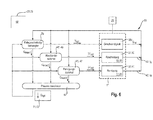
- FIG. 6 The structure of a control and regulating device 68 embodying the process coordinator 67 according to the invention is shown on the basis of a signal flow diagram. It lies within the scope of the invention that the control and regulating device 68 comprising the process coordinator 67 is either from the already described control and regulating device 23 or the driver assistance system 28 is formed.
- the control and regulating device 68 comprises the already described automatic setting machines 45 automatic separator 46 and automatic cleaning machine 47.
- the adjusting machine 45 and the process coordinator 66 receiving control circuit 69 comprises a driving speed of the agricultural machine 1 defining driving speed controller 70. According to the description of the FIGS.
- the agricultural machine 1 has a plurality of sensor systems 26, the various working and quality parameters 37, 40, the travel speed 38c and harvesting crop characteristics. Depending on the driving speed, the sensor systems 26 generate an actual signal Qact of the crop stream passing through the agricultural working machine. Further, the sensor systems 26 assigned to the separating device 10 and the cleaning device 17 generate the separation loss signals IA defining the separation loss 42 and the cleaning loss signals IR defining the cleaning loss 43 ,
- the actual signal Qact of the Ernetgut besatzes is passed within the control loop 69 to the vehicle speed controller 70 as an input signal.
- the deposition loss signals IA are transmitted to the automatic separator 46 and the cleaning loss signals IR to the automatic cleaning machine 47 as their input signals.
- good throughput signals Qmax1, Qmax2, Qmax3 are finally generated from these input signals, which are dependent on the driving speed, dependent on the cleaning loss and depending on the deposition loss, respectively defining the maximum processable throughput of the crop stream 5.
- These good throughput signals Qmax1-3 are then transferred to the process coordinator 67 according to the invention.
- the process coordinator determines from the good throughput signals Qmax1-3 given to it an optimum material throughput and transfers a corresponding optimum material throughput signal Qopt to the cruise control 70 and the automatic adjusting machines 45.
- the optimized good throughput signal Qopt will correspond to the determined lowest value of the maximum material throughputs Qmax1-3.
- the vehicle speed controller 70 finally generates an optimized vehicle speed signal V opt from this, so that the agricultural machine 1 is moved at this optimized vehicle speed.
- the setting machines 45 generate optimized values for a variety of working parameters 37opt of the agricultural machine 1 matched to this optimized material throughput signal Qopt.
- the control loop 69 is run through again in the described manner, so that finally results in a continuously running control process.
- the process coordinator 67 determines, for at least one common parameter 71 of the respective working members 20, a value at which at least the working members 20 monitored by the control and regulating unit 68 operate optimally and this determined value of the at least one common parameter 71 serves as a reference variable 72 is used for the control and regulating device 68.
- the common parameter 71 is not limited to the described optimized Erntegutduchsatz Qopt but can also be related directly to the respective layer height, so then in a similar manner a driving speed-dependent actual layer height and Fahr Anthonysregler- and Einstellautomaten-dependent maximum layer heights result from which then in the process coordinator 67 an optimized layer height is determined. In an analogous manner, the determined optimized layer height will correspond to the lowest values of the determined maximum layer heights.
Landscapes
- Engineering & Computer Science (AREA)
- Software Systems (AREA)
- Artificial Intelligence (AREA)
- Computer Vision & Pattern Recognition (AREA)
- Evolutionary Computation (AREA)
- Medical Informatics (AREA)
- Health & Medical Sciences (AREA)
- Physics & Mathematics (AREA)
- General Physics & Mathematics (AREA)
- Automation & Control Theory (AREA)
- Life Sciences & Earth Sciences (AREA)
- Environmental Sciences (AREA)
- Management, Administration, Business Operations System, And Electronic Commerce (AREA)
- Control Of Position, Course, Altitude, Or Attitude Of Moving Bodies (AREA)
Applications Claiming Priority (2)
| Application Number | Priority Date | Filing Date | Title |
|---|---|---|---|
| DE102012106390 | 2012-07-16 | ||
| DE102013106133.8A DE102013106133A1 (de) | 2012-07-16 | 2013-06-13 | Selbstfahrende landwirtschaftliche Arbeitsmaschine |
Publications (3)
| Publication Number | Publication Date |
|---|---|
| EP2687924A2 true EP2687924A2 (fr) | 2014-01-22 |
| EP2687924A3 EP2687924A3 (fr) | 2017-11-29 |
| EP2687924B1 EP2687924B1 (fr) | 2023-08-16 |
Family
ID=48670396
Family Applications (1)
| Application Number | Title | Priority Date | Filing Date |
|---|---|---|---|
| EP13172057.5A Active EP2687924B1 (fr) | 2012-07-16 | 2013-06-14 | Machine agricole automobile |
Country Status (2)
| Country | Link |
|---|---|
| EP (1) | EP2687924B1 (fr) |
| DE (1) | DE102013106133A1 (fr) |
Cited By (13)
| Publication number | Priority date | Publication date | Assignee | Title |
|---|---|---|---|---|
| EP3076248A1 (fr) * | 2015-04-02 | 2016-10-05 | CLAAS Selbstfahrende Erntemaschinen GmbH | Moissonneuse-batteuse |
| EP3075224A1 (fr) * | 2015-04-02 | 2016-10-05 | CLAAS Selbstfahrende Erntemaschinen GmbH | Moissonneuse-batteuse |
| EP3075223A1 (fr) * | 2015-04-02 | 2016-10-05 | CLAAS Selbstfahrende Erntemaschinen GmbH | Moissonneuse-batteuse |
| EP3085221A1 (fr) * | 2015-04-24 | 2016-10-26 | CLAAS Selbstfahrende Erntemaschinen GmbH | Systeme de recolte comprenant une moissonneuse automobile |
| US10188035B2 (en) | 2014-09-12 | 2019-01-29 | Intelligent Agricultural Solutions Llc | Load-based yield sensor |
| EP3459338A1 (fr) * | 2017-09-26 | 2019-03-27 | CLAAS Selbstfahrende Erntemaschinen GmbH | Machine de travail |
| US10318138B2 (en) * | 2011-03-11 | 2019-06-11 | Intelligent Agricultural Solutions Llc | Harvesting machine capable of automatic adjustment |
| US10321624B2 (en) | 2011-03-11 | 2019-06-18 | Intelligent Agriculture Solutions LLC | Air seeder manifold system |
| US10448569B2 (en) | 2015-12-18 | 2019-10-22 | Claas Selbstfahrende Erntemaschinen Gmbh | Method and apparatus for operating a combine harvester |
| CN110447379A (zh) * | 2018-05-08 | 2019-11-15 | 克拉斯自行式收获机械有限公司 | 联合收割机和用于运行联合收割机的方法 |
| CN112352565A (zh) * | 2020-11-13 | 2021-02-12 | 陈福容 | 一种果蔬幼苗嫁接用截枝剪 |
| EP4154700A1 (fr) * | 2021-09-28 | 2023-03-29 | CLAAS Selbstfahrende Erntemaschinen GmbH | Engin d'abattage-façonnage pourvu de mécanisme de coupe de bande |
| EP4154697A1 (fr) * | 2021-09-28 | 2023-03-29 | CLAAS Selbstfahrende Erntemaschinen GmbH | Système d'aide à la conduite d'un engin d'abattage-façonnage pourvu de mécanisme de coupe de bande |
Families Citing this family (3)
| Publication number | Priority date | Publication date | Assignee | Title |
|---|---|---|---|---|
| US9934538B2 (en) | 2014-09-24 | 2018-04-03 | Deere & Company | Recalling crop-specific performance targets for controlling a mobile machine |
| DE102018111076A1 (de) | 2018-05-08 | 2019-11-14 | Claas Selbstfahrende Erntemaschinen Gmbh | Mähdrescher |
| DE102024123032A1 (de) * | 2024-08-13 | 2026-02-19 | Claas Selbstfahrende Erntemaschinen Gmbh | Landwirtschaftliche Arbeitsmaschine mit Fahrerassistenzsystem |
Family Cites Families (7)
| Publication number | Priority date | Publication date | Assignee | Title |
|---|---|---|---|---|
| DE19514223B4 (de) * | 1995-04-15 | 2005-06-23 | Claas Kgaa Mbh | Verfahren zur Einsatzoptimierung von Landmaschinen |
| DE10147733A1 (de) | 2001-09-27 | 2003-04-10 | Claas Selbstfahr Erntemasch | Verfahren und Vorrichtung zur Ermittlung einer Erntemaschineneinstellung |
| DE102006044628A1 (de) | 2006-09-19 | 2008-04-03 | Claas Selbstfahrende Erntemaschinen Gmbh | Verfahren zur Steuerung einer Anzeigeeinrichtung in einer Erntemaschine |
| DE102007055074A1 (de) * | 2007-11-16 | 2009-05-20 | Claas Selbstfahrende Erntemaschinen Gmbh | Selbstfahrende landwirtschaftliche Arbeitsmaschine |
| DE102007055073A1 (de) * | 2007-11-16 | 2009-05-20 | Claas Selbstfahrende Erntemaschinen Gmbh | Selbstfahrende landwirtschaftliche Erntemaschine |
| DE102009009767A1 (de) | 2009-02-20 | 2010-08-26 | Claas Selbstfahrende Erntemaschinen Gmbh | Fahrerassistenzsystem für landwirtschaftliche Arbeitsmaschine |
| DE102010017676A1 (de) | 2010-07-01 | 2012-01-05 | Claas Selbstfahrende Erntemaschinen Gmbh | Fahrerassistenzsystem für landwirtschaftliche Arbeitsmaschine |
-
2013
- 2013-06-13 DE DE102013106133.8A patent/DE102013106133A1/de not_active Withdrawn
- 2013-06-14 EP EP13172057.5A patent/EP2687924B1/fr active Active
Cited By (20)
| Publication number | Priority date | Publication date | Assignee | Title |
|---|---|---|---|---|
| US10321624B2 (en) | 2011-03-11 | 2019-06-18 | Intelligent Agriculture Solutions LLC | Air seeder manifold system |
| US10318138B2 (en) * | 2011-03-11 | 2019-06-11 | Intelligent Agricultural Solutions Llc | Harvesting machine capable of automatic adjustment |
| US10188035B2 (en) | 2014-09-12 | 2019-01-29 | Intelligent Agricultural Solutions Llc | Load-based yield sensor |
| US9756786B2 (en) | 2015-04-02 | 2017-09-12 | Claas Selbstfahrende Erntemaschinen Gmbh | Combine harvester |
| US9756787B2 (en) | 2015-04-02 | 2017-09-12 | Claas Selbstfahrende Erntemaschinen Gmbh | Combine harvester |
| EP3076248A1 (fr) * | 2015-04-02 | 2016-10-05 | CLAAS Selbstfahrende Erntemaschinen GmbH | Moissonneuse-batteuse |
| US10231380B2 (en) | 2015-04-02 | 2019-03-19 | Claas Selbstfahrende Erntemaschinen Gmbh | Combine harvester |
| RU2708025C2 (ru) * | 2015-04-02 | 2019-12-03 | КЛААС Зельбстфаренде Эрнтемашинен ГмбХ | Зерноуборочный комбайн |
| EP3075223A1 (fr) * | 2015-04-02 | 2016-10-05 | CLAAS Selbstfahrende Erntemaschinen GmbH | Moissonneuse-batteuse |
| EP3075224A1 (fr) * | 2015-04-02 | 2016-10-05 | CLAAS Selbstfahrende Erntemaschinen GmbH | Moissonneuse-batteuse |
| US9807938B2 (en) | 2015-04-24 | 2017-11-07 | Claas Selbstfahrende Erntemaschinen Gmbh | Harvesting system having a self-propelled harvesting machine |
| EP3085221A1 (fr) * | 2015-04-24 | 2016-10-26 | CLAAS Selbstfahrende Erntemaschinen GmbH | Systeme de recolte comprenant une moissonneuse automobile |
| US10448569B2 (en) | 2015-12-18 | 2019-10-22 | Claas Selbstfahrende Erntemaschinen Gmbh | Method and apparatus for operating a combine harvester |
| EP3459338A1 (fr) * | 2017-09-26 | 2019-03-27 | CLAAS Selbstfahrende Erntemaschinen GmbH | Machine de travail |
| CN110447379A (zh) * | 2018-05-08 | 2019-11-15 | 克拉斯自行式收获机械有限公司 | 联合收割机和用于运行联合收割机的方法 |
| CN110447379B (zh) * | 2018-05-08 | 2022-10-28 | 克拉斯自行式收获机械有限公司 | 联合收割机和用于运行联合收割机的方法 |
| CN112352565A (zh) * | 2020-11-13 | 2021-02-12 | 陈福容 | 一种果蔬幼苗嫁接用截枝剪 |
| EP4154700A1 (fr) * | 2021-09-28 | 2023-03-29 | CLAAS Selbstfahrende Erntemaschinen GmbH | Engin d'abattage-façonnage pourvu de mécanisme de coupe de bande |
| EP4154697A1 (fr) * | 2021-09-28 | 2023-03-29 | CLAAS Selbstfahrende Erntemaschinen GmbH | Système d'aide à la conduite d'un engin d'abattage-façonnage pourvu de mécanisme de coupe de bande |
| US12284944B2 (en) | 2021-09-28 | 2025-04-29 | Claas Selbstfahrende Erntemaschinen Gmbh | Harvesting machine with draper using characteristic diagrams |
Also Published As
| Publication number | Publication date |
|---|---|
| EP2687924A3 (fr) | 2017-11-29 |
| EP2687924B1 (fr) | 2023-08-16 |
| DE102013106133A1 (de) | 2014-06-12 |
Similar Documents
| Publication | Publication Date | Title |
|---|---|---|
| EP2687924B1 (fr) | Machine agricole automobile | |
| EP2687923B2 (fr) | Système d'assistance du conducteur pour machine de travail agricole | |
| EP2687922A2 (fr) | Machine de travail agricole dotée d'au moins un dispositif de commande | |
| EP3566564B1 (fr) | Moissonneuse-batteuse et procédé de fonctionnement d'une moissonneuse-batteuse | |
| EP3459338B1 (fr) | Machine de travail | |
| EP1731017B2 (fr) | Méthode de commande d'une moissoneuse | |
| EP3178307B1 (fr) | Engin agricole | |
| EP2322028B1 (fr) | Système d'assistance du conducteur pour machine de travail agricole | |
| EP2220925B1 (fr) | Véhicule de travail agricole et unité d'affichage correspondante | |
| EP2401905B1 (fr) | Procédé de réglage d'au moins un organe de travail d'une moissonneuse automobile | |
| EP1543712B2 (fr) | Procédé et dispositif pour régler les organes de travail d'une moissonneuse-batteuse | |
| EP2401904B2 (fr) | Système d'assistance du conducteur pour machine de travail agricole | |
| EP2042019B1 (fr) | Véhicule de travail agricole | |
| EP1763988B1 (fr) | Procédé de régulation d'un organe de travail d'une récolteuse agricole | |
| EP2060164B1 (fr) | Machine agricole automobile | |
| EP2728523A1 (fr) | Système d'assistance pour l'optimisation du fonctionnement d'un véhicule | |
| EP3501255B1 (fr) | Machine de travail agricole destiné à traiter un processus de travail agricole | |
| EP3132665B1 (fr) | Moissonneuse | |
| DE102020204859A1 (de) | Erntesteuerungssystem mit messerbalken-lasterfassung | |
| EP2110012A2 (fr) | Procédé et dispositif d'optimisation de paramètres de fonctionnement d'une machine de travail agricole | |
| EP1900272B1 (fr) | Machine de travail agricole | |
| EP4091435B1 (fr) | Procédé de détermination des besoins de rectification des lames de hachage d'un dispositif de hachage | |
| DE102024121764A1 (de) | Fahrerassistenzsystem für eine landwirtschaftliche Arbeitsmaschine |
Legal Events
| Date | Code | Title | Description |
|---|---|---|---|
| PUAI | Public reference made under article 153(3) epc to a published international application that has entered the european phase |
Free format text: ORIGINAL CODE: 0009012 |
|
| AK | Designated contracting states |
Kind code of ref document: A2 Designated state(s): AL AT BE BG CH CY CZ DE DK EE ES FI FR GB GR HR HU IE IS IT LI LT LU LV MC MK MT NL NO PL PT RO RS SE SI SK SM TR |
|
| AX | Request for extension of the european patent |
Extension state: BA ME |
|
| RAP1 | Party data changed (applicant data changed or rights of an application transferred) |
Owner name: CLAAS SELBSTFAHRENDE ERNTEMASCHINEN GMBH |
|
| PUAL | Search report despatched |
Free format text: ORIGINAL CODE: 0009013 |
|
| AK | Designated contracting states |
Kind code of ref document: A3 Designated state(s): AL AT BE BG CH CY CZ DE DK EE ES FI FR GB GR HR HU IE IS IT LI LT LU LV MC MK MT NL NO PL PT RO RS SE SI SK SM TR |
|
| AX | Request for extension of the european patent |
Extension state: BA ME |
|
| RIC1 | Information provided on ipc code assigned before grant |
Ipc: G05B 13/02 20060101AFI20171026BHEP Ipc: A01D 41/127 20060101ALI20171026BHEP |
|
| STAA | Information on the status of an ep patent application or granted ep patent |
Free format text: STATUS: REQUEST FOR EXAMINATION WAS MADE |
|
| 17P | Request for examination filed |
Effective date: 20180529 |
|
| RBV | Designated contracting states (corrected) |
Designated state(s): AL AT BE BG CH CY CZ DE DK EE ES FI FR GB GR HR HU IE IS IT LI LT LU LV MC MK MT NL NO PL PT RO RS SE SI SK SM TR |
|
| STAA | Information on the status of an ep patent application or granted ep patent |
Free format text: STATUS: EXAMINATION IS IN PROGRESS |
|
| 17Q | First examination report despatched |
Effective date: 20210126 |
|
| GRAP | Despatch of communication of intention to grant a patent |
Free format text: ORIGINAL CODE: EPIDOSNIGR1 |
|
| STAA | Information on the status of an ep patent application or granted ep patent |
Free format text: STATUS: GRANT OF PATENT IS INTENDED |
|
| INTG | Intention to grant announced |
Effective date: 20230323 |
|
| P01 | Opt-out of the competence of the unified patent court (upc) registered |
Effective date: 20230515 |
|
| GRAS | Grant fee paid |
Free format text: ORIGINAL CODE: EPIDOSNIGR3 |
|
| GRAA | (expected) grant |
Free format text: ORIGINAL CODE: 0009210 |
|
| STAA | Information on the status of an ep patent application or granted ep patent |
Free format text: STATUS: THE PATENT HAS BEEN GRANTED |
|
| AK | Designated contracting states |
Kind code of ref document: B1 Designated state(s): AL AT BE BG CH CY CZ DE DK EE ES FI FR GB GR HR HU IE IS IT LI LT LU LV MC MK MT NL NO PL PT RO RS SE SI SK SM TR |
|
| REG | Reference to a national code |
Ref country code: GB Ref legal event code: FG4D Free format text: NOT ENGLISH |
|
| REG | Reference to a national code |
Ref country code: CH Ref legal event code: EP |
|
| REG | Reference to a national code |
Ref country code: DE Ref legal event code: R096 Ref document number: 502013016443 Country of ref document: DE |
|
| REG | Reference to a national code |
Ref country code: IE Ref legal event code: FG4D Free format text: LANGUAGE OF EP DOCUMENT: GERMAN |
|
| REG | Reference to a national code |
Ref country code: LT Ref legal event code: MG9D |
|
| REG | Reference to a national code |
Ref country code: NL Ref legal event code: MP Effective date: 20230816 |
|
| PG25 | Lapsed in a contracting state [announced via postgrant information from national office to epo] |
Ref country code: GR Free format text: LAPSE BECAUSE OF FAILURE TO SUBMIT A TRANSLATION OF THE DESCRIPTION OR TO PAY THE FEE WITHIN THE PRESCRIBED TIME-LIMIT Effective date: 20231117 |
|
| PG25 | Lapsed in a contracting state [announced via postgrant information from national office to epo] |
Ref country code: IS Free format text: LAPSE BECAUSE OF FAILURE TO SUBMIT A TRANSLATION OF THE DESCRIPTION OR TO PAY THE FEE WITHIN THE PRESCRIBED TIME-LIMIT Effective date: 20231216 |
|
| PG25 | Lapsed in a contracting state [announced via postgrant information from national office to epo] |
Ref country code: SE Free format text: LAPSE BECAUSE OF FAILURE TO SUBMIT A TRANSLATION OF THE DESCRIPTION OR TO PAY THE FEE WITHIN THE PRESCRIBED TIME-LIMIT Effective date: 20230816 Ref country code: RS Free format text: LAPSE BECAUSE OF FAILURE TO SUBMIT A TRANSLATION OF THE DESCRIPTION OR TO PAY THE FEE WITHIN THE PRESCRIBED TIME-LIMIT Effective date: 20230816 Ref country code: PT Free format text: LAPSE BECAUSE OF FAILURE TO SUBMIT A TRANSLATION OF THE DESCRIPTION OR TO PAY THE FEE WITHIN THE PRESCRIBED TIME-LIMIT Effective date: 20231218 Ref country code: NO Free format text: LAPSE BECAUSE OF FAILURE TO SUBMIT A TRANSLATION OF THE DESCRIPTION OR TO PAY THE FEE WITHIN THE PRESCRIBED TIME-LIMIT Effective date: 20231116 Ref country code: NL Free format text: LAPSE BECAUSE OF FAILURE TO SUBMIT A TRANSLATION OF THE DESCRIPTION OR TO PAY THE FEE WITHIN THE PRESCRIBED TIME-LIMIT Effective date: 20230816 Ref country code: LV Free format text: LAPSE BECAUSE OF FAILURE TO SUBMIT A TRANSLATION OF THE DESCRIPTION OR TO PAY THE FEE WITHIN THE PRESCRIBED TIME-LIMIT Effective date: 20230816 Ref country code: LT Free format text: LAPSE BECAUSE OF FAILURE TO SUBMIT A TRANSLATION OF THE DESCRIPTION OR TO PAY THE FEE WITHIN THE PRESCRIBED TIME-LIMIT Effective date: 20230816 Ref country code: IS Free format text: LAPSE BECAUSE OF FAILURE TO SUBMIT A TRANSLATION OF THE DESCRIPTION OR TO PAY THE FEE WITHIN THE PRESCRIBED TIME-LIMIT Effective date: 20231216 Ref country code: HR Free format text: LAPSE BECAUSE OF FAILURE TO SUBMIT A TRANSLATION OF THE DESCRIPTION OR TO PAY THE FEE WITHIN THE PRESCRIBED TIME-LIMIT Effective date: 20230816 Ref country code: GR Free format text: LAPSE BECAUSE OF FAILURE TO SUBMIT A TRANSLATION OF THE DESCRIPTION OR TO PAY THE FEE WITHIN THE PRESCRIBED TIME-LIMIT Effective date: 20231117 Ref country code: FI Free format text: LAPSE BECAUSE OF FAILURE TO SUBMIT A TRANSLATION OF THE DESCRIPTION OR TO PAY THE FEE WITHIN THE PRESCRIBED TIME-LIMIT Effective date: 20230816 |
|
| PG25 | Lapsed in a contracting state [announced via postgrant information from national office to epo] |
Ref country code: PL Free format text: LAPSE BECAUSE OF FAILURE TO SUBMIT A TRANSLATION OF THE DESCRIPTION OR TO PAY THE FEE WITHIN THE PRESCRIBED TIME-LIMIT Effective date: 20230816 |
|
| PG25 | Lapsed in a contracting state [announced via postgrant information from national office to epo] |
Ref country code: ES Free format text: LAPSE BECAUSE OF FAILURE TO SUBMIT A TRANSLATION OF THE DESCRIPTION OR TO PAY THE FEE WITHIN THE PRESCRIBED TIME-LIMIT Effective date: 20230816 |
|
| PG25 | Lapsed in a contracting state [announced via postgrant information from national office to epo] |
Ref country code: SM Free format text: LAPSE BECAUSE OF FAILURE TO SUBMIT A TRANSLATION OF THE DESCRIPTION OR TO PAY THE FEE WITHIN THE PRESCRIBED TIME-LIMIT Effective date: 20230816 Ref country code: RO Free format text: LAPSE BECAUSE OF FAILURE TO SUBMIT A TRANSLATION OF THE DESCRIPTION OR TO PAY THE FEE WITHIN THE PRESCRIBED TIME-LIMIT Effective date: 20230816 Ref country code: ES Free format text: LAPSE BECAUSE OF FAILURE TO SUBMIT A TRANSLATION OF THE DESCRIPTION OR TO PAY THE FEE WITHIN THE PRESCRIBED TIME-LIMIT Effective date: 20230816 Ref country code: EE Free format text: LAPSE BECAUSE OF FAILURE TO SUBMIT A TRANSLATION OF THE DESCRIPTION OR TO PAY THE FEE WITHIN THE PRESCRIBED TIME-LIMIT Effective date: 20230816 Ref country code: DK Free format text: LAPSE BECAUSE OF FAILURE TO SUBMIT A TRANSLATION OF THE DESCRIPTION OR TO PAY THE FEE WITHIN THE PRESCRIBED TIME-LIMIT Effective date: 20230816 Ref country code: CZ Free format text: LAPSE BECAUSE OF FAILURE TO SUBMIT A TRANSLATION OF THE DESCRIPTION OR TO PAY THE FEE WITHIN THE PRESCRIBED TIME-LIMIT Effective date: 20230816 Ref country code: SK Free format text: LAPSE BECAUSE OF FAILURE TO SUBMIT A TRANSLATION OF THE DESCRIPTION OR TO PAY THE FEE WITHIN THE PRESCRIBED TIME-LIMIT Effective date: 20230816 |
|
| REG | Reference to a national code |
Ref country code: DE Ref legal event code: R097 Ref document number: 502013016443 Country of ref document: DE |
|
| PLBE | No opposition filed within time limit |
Free format text: ORIGINAL CODE: 0009261 |
|
| STAA | Information on the status of an ep patent application or granted ep patent |
Free format text: STATUS: NO OPPOSITION FILED WITHIN TIME LIMIT |
|
| 26N | No opposition filed |
Effective date: 20240517 |
|
| PG25 | Lapsed in a contracting state [announced via postgrant information from national office to epo] |
Ref country code: IT Free format text: LAPSE BECAUSE OF FAILURE TO SUBMIT A TRANSLATION OF THE DESCRIPTION OR TO PAY THE FEE WITHIN THE PRESCRIBED TIME-LIMIT Effective date: 20230816 Ref country code: SI Free format text: LAPSE BECAUSE OF FAILURE TO SUBMIT A TRANSLATION OF THE DESCRIPTION OR TO PAY THE FEE WITHIN THE PRESCRIBED TIME-LIMIT Effective date: 20230816 |
|
| PG25 | Lapsed in a contracting state [announced via postgrant information from national office to epo] |
Ref country code: BG Free format text: LAPSE BECAUSE OF FAILURE TO SUBMIT A TRANSLATION OF THE DESCRIPTION OR TO PAY THE FEE WITHIN THE PRESCRIBED TIME-LIMIT Effective date: 20230816 |
|
| PG25 | Lapsed in a contracting state [announced via postgrant information from national office to epo] |
Ref country code: BG Free format text: LAPSE BECAUSE OF FAILURE TO SUBMIT A TRANSLATION OF THE DESCRIPTION OR TO PAY THE FEE WITHIN THE PRESCRIBED TIME-LIMIT Effective date: 20230816 |
|
| PG25 | Lapsed in a contracting state [announced via postgrant information from national office to epo] |
Ref country code: MC Free format text: LAPSE BECAUSE OF FAILURE TO SUBMIT A TRANSLATION OF THE DESCRIPTION OR TO PAY THE FEE WITHIN THE PRESCRIBED TIME-LIMIT Effective date: 20230816 |
|
| REG | Reference to a national code |
Ref country code: CH Ref legal event code: PL |
|
| PG25 | Lapsed in a contracting state [announced via postgrant information from national office to epo] |
Ref country code: LU Free format text: LAPSE BECAUSE OF NON-PAYMENT OF DUE FEES Effective date: 20240614 |
|
| GBPC | Gb: european patent ceased through non-payment of renewal fee |
Effective date: 20240614 |
|
| PG25 | Lapsed in a contracting state [announced via postgrant information from national office to epo] |
Ref country code: IE Free format text: LAPSE BECAUSE OF NON-PAYMENT OF DUE FEES Effective date: 20240614 |
|
| PG25 | Lapsed in a contracting state [announced via postgrant information from national office to epo] |
Ref country code: CH Free format text: LAPSE BECAUSE OF NON-PAYMENT OF DUE FEES Effective date: 20240630 |
|
| PG25 | Lapsed in a contracting state [announced via postgrant information from national office to epo] |
Ref country code: GB Free format text: LAPSE BECAUSE OF NON-PAYMENT OF DUE FEES Effective date: 20240614 |
|
| PGFP | Annual fee paid to national office [announced via postgrant information from national office to epo] |
Ref country code: DE Payment date: 20250618 Year of fee payment: 13 |
|
| PGFP | Annual fee paid to national office [announced via postgrant information from national office to epo] |
Ref country code: BE Payment date: 20250618 Year of fee payment: 13 |
|
| PGFP | Annual fee paid to national office [announced via postgrant information from national office to epo] |
Ref country code: FR Payment date: 20250624 Year of fee payment: 13 |
|
| REG | Reference to a national code |
Ref country code: AT Ref legal event code: MM01 Ref document number: 1600659 Country of ref document: AT Kind code of ref document: T Effective date: 20240614 |
|
| PG25 | Lapsed in a contracting state [announced via postgrant information from national office to epo] |
Ref country code: AT Free format text: LAPSE BECAUSE OF NON-PAYMENT OF DUE FEES Effective date: 20240614 |
|
| PG25 | Lapsed in a contracting state [announced via postgrant information from national office to epo] |
Ref country code: CY Free format text: LAPSE BECAUSE OF FAILURE TO SUBMIT A TRANSLATION OF THE DESCRIPTION OR TO PAY THE FEE WITHIN THE PRESCRIBED TIME-LIMIT; INVALID AB INITIO Effective date: 20130614 |
|
| PG25 | Lapsed in a contracting state [announced via postgrant information from national office to epo] |
Ref country code: HU Free format text: LAPSE BECAUSE OF FAILURE TO SUBMIT A TRANSLATION OF THE DESCRIPTION OR TO PAY THE FEE WITHIN THE PRESCRIBED TIME-LIMIT; INVALID AB INITIO Effective date: 20130614 |