EP3075223A1 - Moissonneuse-batteuse - Google Patents
Moissonneuse-batteuse Download PDFInfo
- Publication number
- EP3075223A1 EP3075223A1 EP16152060.6A EP16152060A EP3075223A1 EP 3075223 A1 EP3075223 A1 EP 3075223A1 EP 16152060 A EP16152060 A EP 16152060A EP 3075223 A1 EP3075223 A1 EP 3075223A1
- Authority
- EP
- European Patent Office
- Prior art keywords
- sensor
- threshing
- computing device
- harvesting process
- combine harvester
- Prior art date
- Legal status (The legal status is an assumption and is not a legal conclusion. Google has not performed a legal analysis and makes no representation as to the accuracy of the status listed.)
- Granted
Links
Images


Classifications
-
- A—HUMAN NECESSITIES
- A01—AGRICULTURE; FORESTRY; ANIMAL HUSBANDRY; HUNTING; TRAPPING; FISHING
- A01D—HARVESTING; MOWING
- A01D41/00—Combines, i.e. harvesters or mowers combined with threshing devices
- A01D41/12—Details of combines
- A01D41/127—Control or measuring arrangements specially adapted for combines
-
- A—HUMAN NECESSITIES
- A01—AGRICULTURE; FORESTRY; ANIMAL HUSBANDRY; HUNTING; TRAPPING; FISHING
- A01D—HARVESTING; MOWING
- A01D41/00—Combines, i.e. harvesters or mowers combined with threshing devices
- A01D41/12—Details of combines
- A01D41/127—Control or measuring arrangements specially adapted for combines
- A01D41/1271—Control or measuring arrangements specially adapted for combines for measuring crop flow
-
- A—HUMAN NECESSITIES
- A01—AGRICULTURE; FORESTRY; ANIMAL HUSBANDRY; HUNTING; TRAPPING; FISHING
- A01D—HARVESTING; MOWING
- A01D41/00—Combines, i.e. harvesters or mowers combined with threshing devices
- A01D41/12—Details of combines
- A01D41/127—Control or measuring arrangements specially adapted for combines
- A01D41/1271—Control or measuring arrangements specially adapted for combines for measuring crop flow
- A01D41/1272—Control or measuring arrangements specially adapted for combines for measuring crop flow for measuring grain flow
-
- A—HUMAN NECESSITIES
- A01—AGRICULTURE; FORESTRY; ANIMAL HUSBANDRY; HUNTING; TRAPPING; FISHING
- A01D—HARVESTING; MOWING
- A01D41/00—Combines, i.e. harvesters or mowers combined with threshing devices
- A01D41/12—Details of combines
- A01D41/127—Control or measuring arrangements specially adapted for combines
- A01D41/1271—Control or measuring arrangements specially adapted for combines for measuring crop flow
- A01D41/1272—Control or measuring arrangements specially adapted for combines for measuring crop flow for measuring grain flow
- A01D41/1273—Control or measuring arrangements specially adapted for combines for measuring crop flow for measuring grain flow for measuring grain loss
-
- A—HUMAN NECESSITIES
- A01—AGRICULTURE; FORESTRY; ANIMAL HUSBANDRY; HUNTING; TRAPPING; FISHING
- A01D—HARVESTING; MOWING
- A01D41/00—Combines, i.e. harvesters or mowers combined with threshing devices
- A01D41/12—Details of combines
- A01D41/127—Control or measuring arrangements specially adapted for combines
- A01D41/1278—Control or measuring arrangements specially adapted for combines for automatic steering
-
- A—HUMAN NECESSITIES
- A01—AGRICULTURE; FORESTRY; ANIMAL HUSBANDRY; HUNTING; TRAPPING; FISHING
- A01F—PROCESSING OF HARVESTED PRODUCE; HAY OR STRAW PRESSES; DEVICES FOR STORING AGRICULTURAL OR HORTICULTURAL PRODUCE
- A01F12/00—Parts or details of threshing apparatus
- A01F12/18—Threshing devices
-
- G—PHYSICS
- G05—CONTROLLING; REGULATING
- G05B—CONTROL OR REGULATING SYSTEMS IN GENERAL; FUNCTIONAL ELEMENTS OF SUCH SYSTEMS; MONITORING OR TESTING ARRANGEMENTS FOR SUCH SYSTEMS OR ELEMENTS
- G05B13/00—Adaptive control systems, i.e. systems automatically adjusting themselves to have a performance which is optimum according to some preassigned criterion
- G05B13/02—Adaptive control systems, i.e. systems automatically adjusting themselves to have a performance which is optimum according to some preassigned criterion electric
- G05B13/04—Adaptive control systems, i.e. systems automatically adjusting themselves to have a performance which is optimum according to some preassigned criterion electric involving the use of models or simulators
Definitions
- the invention relates to a combine harvester having the features of the preamble of claim 1.
- Combines are used for mowing and threshing grain crops.
- the threshing is carried out by a threshing unit, which acquires grain material from the crop picked up by the combine by the cutting device, which is fed to a grain tank after the threshing of a separation and a subsequent cleaning.
- a threshing unit which acquires grain material from the crop picked up by the combine by the cutting device, which is fed to a grain tank after the threshing of a separation and a subsequent cleaning.
- the chaff and straw left over either distributed over the field or, in the case of straw, on swaths e.g. can be placed for later recording by a baler.
- crop is to be understood as meaning the entire crop stream taken up by the threshing unit, that is to say including those grains which have not yet been harvested as grain material from the crop, and the grains which possibly remain in the crop stream as loss and with the straw be filed.
- the grain is grated from the straw by threshing in principle, threshing, and separated from the rest of the crop stream, so that it can be fed directly to the cleaning.
- the remaining crop stream is then fed to the separation area where e.g. the remaining grain is separated from the Erntegutstrom by a shaker assembly and then also supplied to the cleaning.
- Fulfillment of the above quality criteria assumes that the threshing is controlled in a certain way, this way not only of the special quality criteria, but also of various conditions of the environment, the combine and in particular the threshing itself and the nature and Composition of the crop depends.
- the prioritization of one quality criterion regularly means a disadvantage for another quality criterion.
- a combine harvester with a driver assistance system which driver assistance system measures different sizes (eg, drum speed, basket width, grain losses) on the combine harvester and then checks whether they reach a critical value range or critical limits above or below. If this situation occurs, the driver assistance system communicates interactively with the driver by suggesting to the driver measures to control the threshing unit, which should lead out of the critical range of values. The driver can then accept or reject these suggestions, wherein in a next step, if appropriate, alternative suggestions are made to the driver or the suggested measures can be specified more precisely by the driver by means of an input.
- the driver assistance system is equipped with a sensor arrangement which has various sensors for detecting different types of losses such as Ausdrushwanen, Abscheidemaschineen, cleaning losses o. The like.
- a challenge for the realization of the driver assistance system is that different combine harvester equipment can have different, usually complex sensor arrangements and, if necessary, that the respective sensor arrangement can also expand or reduce in the course of a product life cycle of the combine harvester.
- individual sensors of the sensor arrangement may fail due to wear. The former may complicate the manufacture of the combine, the latter aspect may affect the operation of the combine harvester.
- the object of the invention is to improve the known from the prior art combine with driver assistance system with regard to the use of complex sensor systems.
- the invention is based on the idea of initially assigning a sensor configuration to a sensor arrangement, which is defined by the type and scope of ready-to-use sensors of the sensor arrangement, and to carry out the control of the threshing unit as a function of the sensor configuration.
- a functional system model for at least part of the combine harvester is stored in the memory of the driver assistance system, which together with the harvesting process state forms the basis for the particularly autonomous determination of the at least one threshing unit parameter.
- the term "functional system model” means that at least part of the functional relationships within the combine are mapped by the system model. Examples of this are given below.
- the harvesting process state forms a basis for the particularly autonomous determination of the at least one threshing unit parameter, so that the system model is adjusted to the harvesting process state in a manner yet to be explained.
- all state variables are summarized, which are in any way related to the harvesting process. This includes field stock information and / or harvesting process parameters and / or threshing unit parameters and / or environmental information.
- the arithmetic unit the system model underlying the control of the threshing mechanism as a function of the memory in the memory stored sensor configuration defined. This, in turn, takes account of the consideration that, depending on the respectively available, ready-to-operate sensors, there are different possibilities of, in particular, autonomous control of the threshing unit. For example, autonomous control makes sense only as a function of such harvesting process parameters, which can also be determined by the sensor arrangement.
- the threshing together with the driver assistance system forms a threshing machine.
- the driver assistance system with its memory for storing data and its computing device is set up to autonomously determine individual machine parameters of the threshing mechanism and predefine the threshing mechanism.
- machine parameters are referred to herein as "threshing unit parameters”.
- the basis for the determination of the threshing unit parameters is a user-side selection of harvesting process strategies that are stored in the memory of the driver assistance system. As a result, with a one-time selection of the active harvesting strategy by the driver, a manner of controlling the threshing unit can be specified.
- a further input from the driver is not required.
- the driver has the option to change the selected harvesting strategy if desired, so that then continues an autonomous control takes place, but then possibly with a different prioritization.
- a parameter group of harvesting process parameters is defined, to each of which at least one characteristic field is assigned, wherein the harvesting process parameter is the output variable of the respective characteristic field.
- the parameter group is preferably defined by the computing device as a function of the sensor configuration, that is, as a function of the sensory detectability of different harvest process parameters.
- An above characteristic field forms here and preferably quite generally the dependence of an output variable on at least one input variable, in particular on two or more input variables.
- the computing device at least one of the characteristic fields in the current harvesting operation, preferably cyclically, matches the actual harvesting process state, wherein the definition of the system model by the arithmetic unit in dependence on the memory stored in the sensor configuration in addition to the definition of the characteristic fields also includes a definition of the balancing of the system model.
- the definition of the adjustment includes information on whether the characteristic field in question should be calibrated sensor-based (claim 6) or whether the characteristic field in question should in principle not be adjusted (claim 7). In both cases, it is preferably possible to intervene on the user side (claim 8).
- cyclic in the present case is always to be understood broadly and here means a continuous respective activity with a constant, but also changing cycle time.
- the further preferred embodiment according to claim 9 takes into account the fact that the respective current sensor configuration can change in particular by a wear-related failure of a sensor.
- the computing device carries out a cyclical check of the sensors in particular and deposits the resulting sensor configuration in the memory.
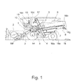
- a combine harvester comprises a threshing unit 1 for threshing picked-up harvested crops to produce grain. Under the crop is understood to mean the entire recorded from the field inventory and the threshing 1 fed material, the grain then called the combine to be recovered from the crop grains. As in Fig. 1 can be seen, a field inventory is mowed by a cutting unit 2 of the combine and the thus obtained crop fed by a feeder 3 to the threshing unit 1.
- the threshing unit 1 is equipped with a threshing drum 4, which cooperates with a concave 5.
- the threshing 1 is deposited downstream of a deposition 6 process technology.
- the crop stream fed to the threshing unit 1 is subsequently fed to the separating arrangement 6-without the grain material already obtained here.
- the threshing unit 1 is used to rub the majority of the grain from the straw of the crop by threshing.
- the crop is then moved with the remaining grain fraction in it, z. B. shaken that the remaining grain is separated out as possible from the straw and other crops.
- the grain material obtained in the threshing unit 1 and the separating arrangement 6 is then fed to a cleaning arrangement 7.
- the cleaning arrangement 7 which is regularly multi-stage, non-grain constituents entrained in the grain material, e.g. Chaff and straw parts, as well as unmuffled material, such as spike or awn, separated from the grain.
- the cleaned grain material passes over a transport arrangement 9, e.g. a grain elevator, into a grain tank 9a.
- the threshed straw - so the remaining crop in the Abscheidean Aunt 6 - is stored by the combine, z. B. as a swath along the lane.
- An above threshing unit 1 can be controlled by specifying various machine parameters. These include, depending on the structure of the threshing 1 drive parameters such as a drum speed 1a or other movement characteristics of the threshing cylinder 4 and a basket width 1b - ie the distance between the threshing drum 4 and a concave 5. If the threshing 1 has Entbanner flaps, these can also in the frame the control of the threshing unit 1 are adjusted.
- the proposed combine harvester further comprises a driver assistance system 10 for controlling the threshing unit 1.
- This driver assistance system 10 comprises a memory 11 for storing data - that is to say a memory in the information technology sense - and a computing device 12 for processing the data stored in the memory 11.
- the driver assistance system 10 is configured to assist a driver 13 of the combine in operating the combine harvester.
- the driver assistance system 10 with the memory 11 and the computing device 12 is shown schematically in FIG Fig. 2 shown.
- a sensor arrangement 15 for detecting at least part of the current harvesting process state, here with several Sensors 16 is equipped. Examples of the various sensors 16 will be discussed below.
- the sensor assembly 15 is associated with a sensor configuration 11 c, which is defined by the nature and extent of ready sensors 16 of the sensor assembly 15 and stored in the memory 11 or stored.
- a functional system model 11 b is stored in the memory 11 for at least part of the combine, wherein the computing device 12 is set up to carry out a particularly autonomous determination of at least one threshing unit parameter 1 a, 1 b based on the system model 11 b and the harvesting process state.
- the functional system model 11 b is a computational model for mapping functional relationships within the combine harvester. Examples of such functional relationships are explained below.
- the arithmetic unit 12 defines the system model 11 b on which the control of the threshing mechanism 1 is based, as a function of the sensor configuration 11 c stored in the memory 11. This will be explained below by way of examples.
- the threshing unit 1 together with the driver assistance system 10 forms a threshing machine 14.
- a plurality of selectable harvesting process strategies 11a are stored in the storage 11 and the computing device 12 is set up to implement the selected harvesting process strategy 11a or the harvesting process strategies 11a autonomously determine at least one machine parameter for the threshing unit 1 and specify the threshing unit 1.
- Such machine parameters for the threshing unit 1 are referred to herein as "threshing unit parameters”.
- a threshing machine 14 is provided, which controls all relevant to the work of the threshing unit 1 sizes coordinated with each other. It is thus avoided in particular that competing and possibly mutually canceling controls take place from different sources. Instead, all relevant parameters are controlled "from a single source”.
- the driver 13 a desired provide a qualitative result and do not need their own expertise on the detailed details required for this outcome.
- the determination of the threshing unit parameters is an autonomous determination to the extent that, in principle, the harvesting process strategy 11a is implemented by the computing device 12, without intervening in the determination of the threshing mechanism parameters 1a, 1b in the narrower sense, intervention of the driver 13 or a query the driver 13 is necessary. Such an intervention of the driver 13 is therefore still possible in principle, but not required.
- the stored harvesting process strategies 11a differ in the target setting or the optimization of harvesting process parameters, as will be explained.
- the driver assistance system 10 can basically be designed centrally. It serves to control not only the threshing unit 1, but also upstream and downstream working organs, such as the cutting unit 2, the inclined conveyor 3, the deposition assembly 6, the cleaning assembly 7 and the distribution assembly 8. Basically, it is conceivable that the driver assistance system 10th is decentralized and composed of a number of individual tax systems. Then it can be provided, for example, that at least a part of the working elements of the combine each have an associated, decentralized control system.
- the system model 11 b is preferably adjusted by the computing device 12 in the current harvesting operation to the current harvesting process state. This means that the computing device 12 checks whether the functional relationships depicted in the system model 11 b match the actual harvesting process state. If deviations result during this check, the computing device 12 makes a corresponding change to the system model 11b.
- This adjustment is carried out cyclically in a particularly preferred embodiment, wherein reference may be made to the general part of the description in view of the broad understanding of the term "cyclic".
- the computing device 12 determines the threshing mechanism parameters in the above sense cyclically. In this context, too, reference may be made to the broad understanding of the term "cyclical".
- the term “harvesting process state” includes all information related to the harvesting process. This includes field inventory information such as “stock density”, “thresheability of stock” and “inventory moisture”. Furthermore, the harvest process parameter “expressions losses” as a measure of the non-threshed grains deposited on the field, the harvesting parameter “fraction fractions” as a measure of the fractured grains deposited in the grain tank, the harvesting process parameter “layer height” as a measure of throughput , the harvesting process parameter “deposition losses” as a measure of the grains deposited by the deposition assembly 6 on the field, the harvesting process parameter “cleaning losses” as a measure of the grains deposited on the field by the cleaning assembly 7, the harvesting process parameter “slip-thresher-drive” Measure of threshing load and the harvesting process parameter "fuel consumption” as a measure of the energy consumption of the threshing unit drive. Finally, this includes threshing unit parameters such as "drum speed” and “basket width” as well as environmental information
- layer height may be noted that this term is interpreted broadly and includes both the layer height of the absorbed by the threshing good stream in the strict sense as well as the throughput of passing through the threshing 1 good stream. In that regard, all statements on the layer height apply equally to the throughput. In particular, the term “layer height” in the present case can be replaced by the term “throughput”.
- the sensor arrangement 15 may have different sensors 16.
- one or more of the crop process parameters may or may not "Exposure loss” by an expression loss sensor 16a, "fraction fraction” by a fractional grain sensor 16d, “slice height” by a slice height sensor 16f, “trap loss” by a trap loss sensor 16b, “cleaning loss” by a washer loss sensor 16e, "slip thresher driver” by a slip sensor 16c and "fuel consumption” can be determined by a fuel consumption sensor, not shown.
- the sensor assembly 15 - as also in the Fig. 1 shown - have a Schwadsensor 16g for detecting a swathing information.
- a swirl sensor 16g can be used with a suitable design for detecting a grain fraction in the swath 18.
- the questionable, selectable by the driver 13 harvesting process strategies 11a are each directed to different targets.
- at least one harvesting process strategy 11 a is based on the target of setting or optimizing at least one harvesting process parameter such as "expressions losses”, “fraction fraction”, “separation losses”, “cleaning losses”, “slip thresher drive”, “fuel consumption” or the like the like.
- the implementation of the harvesting process strategies 11a is to take place in each case by a corresponding specification of threshing mechanism parameters, here and preferably the threshing mechanism parameters "drum rotation speed” and "basket width", which are in the foreground for the activation of the threshing unit 1.
- a parameter group of crop process parameters is defined, to which at least one stored in the memory 11, functional relationships of the combine mapping characteristic map AJ of the system model 11 b is assigned, wherein the respective crop process parameter is the output of the associated, at least one characteristic field AJ ,
- the harvesting process parameter "layer height” and a threshing unit parameter are defined as input variables for the at least one characteristic field AJ.
- the above-explained adjustment of the system model 11 b to the current crop process state is carried out in the case of the system model 11 b with at least one characteristic A-J preferably in that the computing device 12 at least one of the characteristic fields A-J in the current harvesting operation, in particular cyclically, on the harvesting process state.
- the computing device 12 makes a change in the respective characteristic field AJ in order to achieve an approximation of the characteristic field AJ to the real sensor measured values.
- the entire characteristic field AJ in the direction of the respective output variable in the Fig. 3 to 7 move up or down.
- the approximation of the characteristic field AJ is such that it also brings about a change in the characteristics of the respective characteristic curves.
- the computing device 12 assigns different characteristics to the above characteristic fields A-J with regard to a possible adjustment.
- the computing device 12 defines at least one of the characteristic curves A-J as a dynamic characteristic field and during the current harvesting operation, in particular cyclically, adjusts to the sensory harvesting process state.
- the computing device 12 defines the assigned characteristic field AJ as a static characteristic field for at least one harvesting process parameter of the parameter group and does not subject it to matching with the sensorially detected harvesting process state. This is Preferably, the case when the relevant harvesting process parameter according to the sensor configuration 11 c can not be determined by the sensor assembly 15, a corresponding sensor 16 is therefore not present or ready for operation.
- the computing device 12 it is preferable for the computing device 12 to allow a user-side input to the harvesting process parameter or the harvesting process parameter via an input / output device 19 for at least one harvesting process parameter of the parameter group, in particular as a function of the sensor configuration 11 c.
- the computing device 12 compares the characteristic map A-J in question based on the user input.
- the particular autonomous determination of the at least one threshing mechanism parameter 1a, 1b is carried out based on the user-input.
- the computing device 12 generates queries relating to the respective harvesting process parameter and outputs them via the input / output device 19.
- the driver 13 may input at least a portion of the harvesting process status via the input / output device.
- the input / output device 19 has corresponding input elements 20a and output elements 20b.
- the computing device 12 checks, in particular cyclically, whether all the sensors 16 are operable in accordance with the sensor configuration 11 c stored in the memory 11. For the operating case that one sensor 16 or several sensors 16 is / are inoperative, the computing device 12 undertakes a corresponding modification of the sensor configuration 11 c and stores it in the memory 11. Thus, the new sensor configuration 11 c can be considered in further operation as explained above.
- the computing device 12 defines the characteristic fields G, H, A, B assigned to the harvesting process parameters "broken grain” and “expressive” Fig. 6 . 3 ) preferably as static characteristics fields and the cropping process parameters "deposition losses” and "cleaning losses” associated characteristic fields C, D, I, J ( Fig. 4 . 7 ) as dynamic characteristic fields.
- the computing device 12 defines the map A, B associated with the harvesting process parameter "expressive losses". Fig. 3 ) as a static characteristic field and the characteristic process fields C, D, I, J, G, H assigned to the harvesting process parameters "separation losses", “cleaning losses” and “breakage grain losses” Fig. 4 . 7 . 6 ) as dynamic characteristic fields.
- the computing device 12 defines the characteristic fields associated with the harvesting process parameters "deposition losses,””cleaninglosses,””breakage grain losses," and “expressive losses.” C, D, I, J, G, H, A, B ( Fig. 4 . 7 . 6 . 3 ) as dynamic characteristic fields.
Landscapes
- Environmental Sciences (AREA)
- Life Sciences & Earth Sciences (AREA)
- Engineering & Computer Science (AREA)
- Evolutionary Computation (AREA)
- Artificial Intelligence (AREA)
- Computer Vision & Pattern Recognition (AREA)
- Health & Medical Sciences (AREA)
- Medical Informatics (AREA)
- Software Systems (AREA)
- Physics & Mathematics (AREA)
- General Physics & Mathematics (AREA)
- Automation & Control Theory (AREA)
- Combines (AREA)
- Harvester Elements (AREA)
- Threshing Machine Elements (AREA)
Priority Applications (1)
| Application Number | Priority Date | Filing Date | Title |
|---|---|---|---|
| PL16152060T PL3075223T3 (pl) | 2015-04-02 | 2016-01-20 | Kombajn zbożowy |
Applications Claiming Priority (1)
| Application Number | Priority Date | Filing Date | Title |
|---|---|---|---|
| DE102015004343.9A DE102015004343A1 (de) | 2015-04-02 | 2015-04-02 | Mähdrescher |
Publications (2)
| Publication Number | Publication Date |
|---|---|
| EP3075223A1 true EP3075223A1 (fr) | 2016-10-05 |
| EP3075223B1 EP3075223B1 (fr) | 2019-12-04 |
Family
ID=55182266
Family Applications (1)
| Application Number | Title | Priority Date | Filing Date |
|---|---|---|---|
| EP16152060.6A Active EP3075223B1 (fr) | 2015-04-02 | 2016-01-20 | Moissonneuse-batteuse |
Country Status (6)
| Country | Link |
|---|---|
| US (1) | US10231380B2 (fr) |
| EP (1) | EP3075223B1 (fr) |
| CA (1) | CA2921731C (fr) |
| DE (1) | DE102015004343A1 (fr) |
| PL (1) | PL3075223T3 (fr) |
| RU (1) | RU2708842C2 (fr) |
Cited By (2)
| Publication number | Priority date | Publication date | Assignee | Title |
|---|---|---|---|---|
| CN112042371A (zh) * | 2020-10-13 | 2020-12-08 | 中国农业大学 | 一种玉米籽粒清选损失监测系统及方法 |
| EP4663000A1 (fr) * | 2024-06-12 | 2025-12-17 | CLAAS Selbstfahrende Erntemaschinen GmbH | Machine de travail agricole dotée d'au moins un dispositif de commande |
Families Citing this family (74)
| Publication number | Priority date | Publication date | Assignee | Title |
|---|---|---|---|---|
| WO2018175641A1 (fr) * | 2017-03-21 | 2018-09-27 | Blue River Technology Inc. | Moissonneuse-batteuse comprenant une commande à rétroaction de machine |
| US11140807B2 (en) * | 2017-09-07 | 2021-10-12 | Deere & Company | System for optimizing agricultural machine settings |
| DE102018104286A1 (de) * | 2018-02-26 | 2019-08-29 | Claas Selbstfahrende Erntemaschinen Gmbh | Selbstfahrender Feldhäcksler |
| DE102018108405A1 (de) * | 2018-04-10 | 2019-10-10 | Claas Selbstfahrende Erntemaschinen Gmbh | Mähdrescher sowie Verfahren zu dessen Steuerung |
| US12069978B2 (en) | 2018-10-26 | 2024-08-27 | Deere & Company | Predictive environmental characteristic map generation and control system |
| US11467605B2 (en) | 2019-04-10 | 2022-10-11 | Deere & Company | Zonal machine control |
| US11079725B2 (en) | 2019-04-10 | 2021-08-03 | Deere & Company | Machine control using real-time model |
| US11589509B2 (en) | 2018-10-26 | 2023-02-28 | Deere & Company | Predictive machine characteristic map generation and control system |
| US11641800B2 (en) | 2020-02-06 | 2023-05-09 | Deere & Company | Agricultural harvesting machine with pre-emergence weed detection and mitigation system |
| US11957072B2 (en) | 2020-02-06 | 2024-04-16 | Deere & Company | Pre-emergence weed detection and mitigation system |
| US11178818B2 (en) | 2018-10-26 | 2021-11-23 | Deere & Company | Harvesting machine control system with fill level processing based on yield data |
| US11240961B2 (en) | 2018-10-26 | 2022-02-08 | Deere & Company | Controlling a harvesting machine based on a geo-spatial representation indicating where the harvesting machine is likely to reach capacity |
| US11672203B2 (en) | 2018-10-26 | 2023-06-13 | Deere & Company | Predictive map generation and control |
| US11653588B2 (en) | 2018-10-26 | 2023-05-23 | Deere & Company | Yield map generation and control system |
| US11234366B2 (en) | 2019-04-10 | 2022-02-01 | Deere & Company | Image selection for machine control |
| US11778945B2 (en) | 2019-04-10 | 2023-10-10 | Deere & Company | Machine control using real-time model |
| DE102019119126A1 (de) * | 2019-07-15 | 2021-01-21 | Claas Selbstfahrende Erntemaschinen Gmbh | Landwirtschaftliche Erntemaschine |
| US12035648B2 (en) | 2020-02-06 | 2024-07-16 | Deere & Company | Predictive weed map generation and control system |
| US12329148B2 (en) | 2020-02-06 | 2025-06-17 | Deere & Company | Predictive weed map and material application machine control |
| US12225846B2 (en) | 2020-02-06 | 2025-02-18 | Deere & Company | Machine control using a predictive map |
| US11477940B2 (en) | 2020-03-26 | 2022-10-25 | Deere & Company | Mobile work machine control based on zone parameter modification |
| US11592822B2 (en) | 2020-10-09 | 2023-02-28 | Deere & Company | Machine control using a predictive map |
| US20220110238A1 (en) | 2020-10-09 | 2022-04-14 | Deere & Company | Machine control using a predictive map |
| US11874669B2 (en) | 2020-10-09 | 2024-01-16 | Deere & Company | Map generation and control system |
| US11474523B2 (en) | 2020-10-09 | 2022-10-18 | Deere & Company | Machine control using a predictive speed map |
| US11675354B2 (en) | 2020-10-09 | 2023-06-13 | Deere & Company | Machine control using a predictive map |
| US11825768B2 (en) | 2020-10-09 | 2023-11-28 | Deere & Company | Machine control using a predictive map |
| US12386354B2 (en) | 2020-10-09 | 2025-08-12 | Deere & Company | Predictive power map generation and control system |
| US11864483B2 (en) | 2020-10-09 | 2024-01-09 | Deere & Company | Predictive map generation and control system |
| US12419220B2 (en) | 2020-10-09 | 2025-09-23 | Deere & Company | Predictive map generation and control system |
| US11946747B2 (en) | 2020-10-09 | 2024-04-02 | Deere & Company | Crop constituent map generation and control system |
| US11927459B2 (en) | 2020-10-09 | 2024-03-12 | Deere & Company | Machine control using a predictive map |
| US11635765B2 (en) | 2020-10-09 | 2023-04-25 | Deere & Company | Crop state map generation and control system |
| US11889788B2 (en) | 2020-10-09 | 2024-02-06 | Deere & Company | Predictive biomass map generation and control |
| US11727680B2 (en) | 2020-10-09 | 2023-08-15 | Deere & Company | Predictive map generation based on seeding characteristics and control |
| US11871697B2 (en) | 2020-10-09 | 2024-01-16 | Deere & Company | Crop moisture map generation and control system |
| US20220110258A1 (en) | 2020-10-09 | 2022-04-14 | Deere & Company | Map generation and control system |
| US11845449B2 (en) | 2020-10-09 | 2023-12-19 | Deere & Company | Map generation and control system |
| US11895948B2 (en) | 2020-10-09 | 2024-02-13 | Deere & Company | Predictive map generation and control based on soil properties |
| US12013245B2 (en) | 2020-10-09 | 2024-06-18 | Deere & Company | Predictive map generation and control system |
| US11849672B2 (en) | 2020-10-09 | 2023-12-26 | Deere & Company | Machine control using a predictive map |
| US11711995B2 (en) | 2020-10-09 | 2023-08-01 | Deere & Company | Machine control using a predictive map |
| US11983009B2 (en) | 2020-10-09 | 2024-05-14 | Deere & Company | Map generation and control system |
| US11650587B2 (en) | 2020-10-09 | 2023-05-16 | Deere & Company | Predictive power map generation and control system |
| US12550802B2 (en) | 2020-10-08 | 2026-02-17 | Deere & Company | Predictive machine characteristic map generation and control system |
| US12422847B2 (en) | 2020-10-09 | 2025-09-23 | Deere & Company | Predictive agricultural model and map generation |
| US12178158B2 (en) | 2020-10-09 | 2024-12-31 | Deere & Company | Predictive map generation and control system for an agricultural work machine |
| US12069986B2 (en) | 2020-10-09 | 2024-08-27 | Deere & Company | Map generation and control system |
| US11844311B2 (en) | 2020-10-09 | 2023-12-19 | Deere & Company | Machine control using a predictive map |
| US11849671B2 (en) | 2020-10-09 | 2023-12-26 | Deere & Company | Crop state map generation and control system |
| US12250905B2 (en) | 2020-10-09 | 2025-03-18 | Deere & Company | Machine control using a predictive map |
| US11889787B2 (en) | 2020-10-09 | 2024-02-06 | Deere & Company | Predictive speed map generation and control system |
| US12127500B2 (en) | 2021-01-27 | 2024-10-29 | Deere & Company | Machine control using a map with regime zones |
| US20230034308A1 (en) * | 2021-07-28 | 2023-02-02 | Cnh Industrial America Llc | Agricultural management system and methods |
| DE102021125124A1 (de) | 2021-09-28 | 2023-03-30 | Claas Selbstfahrende Erntemaschinen Gmbh | Landwirtschaftliche Arbeitsmaschine mit Kennfeldsteuerung |
| DE102021125099A1 (de) | 2021-09-28 | 2023-03-30 | Claas Selbstfahrende Erntemaschinen Gmbh | Erntemaschine mit Bandschneidwerk |
| US12229886B2 (en) | 2021-10-01 | 2025-02-18 | Deere & Company | Historical crop state model, predictive crop state map generation and control system |
| US12310286B2 (en) | 2021-12-14 | 2025-05-27 | Deere & Company | Crop constituent sensing |
| US12302791B2 (en) | 2021-12-20 | 2025-05-20 | Deere & Company | Crop constituents, predictive mapping, and agricultural harvester control |
| US12245549B2 (en) | 2022-01-11 | 2025-03-11 | Deere & Company | Predictive response map generation and control system |
| US12520759B2 (en) | 2022-01-26 | 2026-01-13 | Deere & Company | Systems and methods for predicting material dynamics |
| US12082531B2 (en) | 2022-01-26 | 2024-09-10 | Deere & Company | Systems and methods for predicting material dynamics |
| US12295288B2 (en) | 2022-04-05 | 2025-05-13 | Deere &Company | Predictive machine setting map generation and control system |
| US12298767B2 (en) | 2022-04-08 | 2025-05-13 | Deere & Company | Predictive material consumption map and control |
| US12582035B2 (en) | 2022-04-08 | 2026-03-24 | Deere & Company | Systems and methods for predictive power requirements and control |
| US12358493B2 (en) | 2022-04-08 | 2025-07-15 | Deere & Company | Systems and methods for predictive power requirements and control |
| US12058951B2 (en) | 2022-04-08 | 2024-08-13 | Deere & Company | Predictive nutrient map and control |
| US12284934B2 (en) | 2022-04-08 | 2025-04-29 | Deere & Company | Systems and methods for predictive tractive characteristics and control |
| US12310285B2 (en) | 2023-02-27 | 2025-05-27 | Deere & Company | Agricultural operation evaluation system and method |
| US12568881B2 (en) | 2023-03-07 | 2026-03-10 | Deere & Company | Measuring loss and calibrating loss sensors on an agricultural harvester |
| USD1084021S1 (en) | 2023-09-20 | 2025-07-15 | Deere &Company | Display screen or portion thereof with graphical user interface |
| USD1083987S1 (en) | 2023-09-20 | 2025-07-15 | Deere & Company | Display screen or portion thereof with graphical user interface |
| USD1082823S1 (en) | 2023-09-20 | 2025-07-08 | Deere & Company | Display screen or portion thereof with graphical user interface |
| DE102024119411A1 (de) | 2024-07-09 | 2026-01-15 | Claas Selbstfahrende Erntemaschinen Gmbh | Mähdrescher sowie Verfahren zum Betreiben eines Mähdreschers |
Citations (6)
| Publication number | Priority date | Publication date | Assignee | Title |
|---|---|---|---|---|
| EP1543712A1 (fr) * | 2003-12-19 | 2005-06-22 | CLAAS Selbstfahrende Erntemaschinen GmbH | Procédé et dispositif pour régler les organes de travail d'une moissonneuse-batteuse |
| EP1902609A1 (fr) * | 2006-09-19 | 2008-03-26 | CLAAS Selbstfahrende Erntemaschinen GmbH | Procédé destiné à la commande d un dispositif d affichage dans une moissonneuse |
| DE102009009767A1 (de) | 2009-02-20 | 2010-08-26 | Claas Selbstfahrende Erntemaschinen Gmbh | Fahrerassistenzsystem für landwirtschaftliche Arbeitsmaschine |
| EP2687924A2 (fr) * | 2012-07-16 | 2014-01-22 | CLAAS Selbstfahrende Erntemaschinen GmbH | Machine agricole automobile |
| EP2728523A1 (fr) * | 2012-11-05 | 2014-05-07 | CLAAS Selbstfahrende Erntemaschinen GmbH | Système d'assistance pour l'optimisation du fonctionnement d'un véhicule |
| EP2837279A2 (fr) * | 2013-08-12 | 2015-02-18 | Deere & Company | Système d'assistance au conducteur |
Family Cites Families (6)
| Publication number | Priority date | Publication date | Assignee | Title |
|---|---|---|---|---|
| US4296409A (en) * | 1979-03-12 | 1981-10-20 | Dickey-John Corporation | Combine performance monitor |
| SU1720545A1 (ru) * | 1986-10-08 | 1992-03-23 | Головное специализированное конструкторское бюро по комплексам зерноуборочных машин Производственного объединения "Ростсельмаш" | Способ автоматического управлени технологическим процессом зерноуборочного комбайна |
| US6553300B2 (en) * | 2001-07-16 | 2003-04-22 | Deere & Company | Harvester with intelligent hybrid control system |
| DE102005026159A1 (de) | 2005-06-06 | 2007-01-25 | Claas Selbstfahrende Erntemaschinen Gmbh | Verfahren zur Steuerung einer Erntemaschine |
| DE102010017687A1 (de) * | 2010-07-01 | 2012-01-05 | Claas Selbstfahrende Erntemaschinen Gmbh | Verfahren zur Einstellung zumindest eines Arbeitsorganes einer selbstfahrenden Erntemaschine |
| DE102013201996A1 (de) * | 2013-02-07 | 2014-08-07 | Deere & Company | Verfahren zur Einstellung von Arbeitsparametern einer Erntemaschine |
-
2015
- 2015-04-02 DE DE102015004343.9A patent/DE102015004343A1/de not_active Withdrawn
-
2016
- 2016-01-20 PL PL16152060T patent/PL3075223T3/pl unknown
- 2016-01-20 EP EP16152060.6A patent/EP3075223B1/fr active Active
- 2016-02-25 CA CA2921731A patent/CA2921731C/fr active Active
- 2016-03-23 RU RU2016110485A patent/RU2708842C2/ru active
- 2016-03-30 US US15/084,686 patent/US10231380B2/en active Active
Patent Citations (6)
| Publication number | Priority date | Publication date | Assignee | Title |
|---|---|---|---|---|
| EP1543712A1 (fr) * | 2003-12-19 | 2005-06-22 | CLAAS Selbstfahrende Erntemaschinen GmbH | Procédé et dispositif pour régler les organes de travail d'une moissonneuse-batteuse |
| EP1902609A1 (fr) * | 2006-09-19 | 2008-03-26 | CLAAS Selbstfahrende Erntemaschinen GmbH | Procédé destiné à la commande d un dispositif d affichage dans une moissonneuse |
| DE102009009767A1 (de) | 2009-02-20 | 2010-08-26 | Claas Selbstfahrende Erntemaschinen Gmbh | Fahrerassistenzsystem für landwirtschaftliche Arbeitsmaschine |
| EP2687924A2 (fr) * | 2012-07-16 | 2014-01-22 | CLAAS Selbstfahrende Erntemaschinen GmbH | Machine agricole automobile |
| EP2728523A1 (fr) * | 2012-11-05 | 2014-05-07 | CLAAS Selbstfahrende Erntemaschinen GmbH | Système d'assistance pour l'optimisation du fonctionnement d'un véhicule |
| EP2837279A2 (fr) * | 2013-08-12 | 2015-02-18 | Deere & Company | Système d'assistance au conducteur |
Cited By (3)
| Publication number | Priority date | Publication date | Assignee | Title |
|---|---|---|---|---|
| CN112042371A (zh) * | 2020-10-13 | 2020-12-08 | 中国农业大学 | 一种玉米籽粒清选损失监测系统及方法 |
| CN112042371B (zh) * | 2020-10-13 | 2021-07-20 | 中国农业大学 | 一种玉米籽粒清选损失监测系统及方法 |
| EP4663000A1 (fr) * | 2024-06-12 | 2025-12-17 | CLAAS Selbstfahrende Erntemaschinen GmbH | Machine de travail agricole dotée d'au moins un dispositif de commande |
Also Published As
| Publication number | Publication date |
|---|---|
| CA2921731A1 (fr) | 2016-10-02 |
| RU2708842C2 (ru) | 2019-12-11 |
| CA2921731C (fr) | 2025-05-13 |
| EP3075223B1 (fr) | 2019-12-04 |
| US10231380B2 (en) | 2019-03-19 |
| US20160286721A1 (en) | 2016-10-06 |
| RU2016110485A (ru) | 2017-09-28 |
| DE102015004343A1 (de) | 2016-10-06 |
| RU2016110485A3 (fr) | 2019-05-29 |
| PL3075223T3 (pl) | 2020-06-29 |
Similar Documents
| Publication | Publication Date | Title |
|---|---|---|
| EP3075223B1 (fr) | Moissonneuse-batteuse | |
| EP3132711B1 (fr) | Moissonneuse agricole | |
| EP3180974B1 (fr) | Procédé de fonctionnement d'une moissonneuse-batteuse | |
| EP3075224B1 (fr) | Moissonneuse-batteuse | |
| EP3076248B1 (fr) | Moissonneuse-batteuse | |
| EP3085221B1 (fr) | Système de récolte comprenant une moissonneuse automobile | |
| EP3358932B2 (fr) | Procede de fonctionnement d'une moissonneuse a l'aide d'un modele de croissance de plante | |
| EP3494771B2 (fr) | Dispositif de hauteur de coupe automatique | |
| EP3566563A1 (fr) | Moissonneuse-batteuse | |
| DE102017122300A1 (de) | Arbeitsmaschine | |
| EP3097759A1 (fr) | Procede de commande d'une moissonneuse automotrice | |
| DE102017208442A1 (de) | Selbstlernende, Korrektureingaben berücksichtigende Anordnung zur selbsttätigen Kontrolle eines Arbeitsparameters einer Erntegutförder- und/oder -bearbeitungseinrichtung | |
| DE102018111077A1 (de) | Mähdrescher sowie Verfahren zum Betreiben eines Mähdreschers | |
| EP3586596A1 (fr) | Engin de travail agricole | |
| DE102005014278A1 (de) | Verfahren zur Ermittlung eines Ziel-Einstellwerts | |
| DE102021121296A1 (de) | Verfahren für den Betrieb einer selbstfahrenden landwirtschaftlichen Erntemaschine sowie selbstfahrende landwirtschaftliche Erntemaschine | |
| EP4154699B1 (fr) | Machine de travail agricole pourvu à commande de champ caractéristique | |
| EP3967128A1 (fr) | Ramasseuse-hacheuse | |
| EP4154697B1 (fr) | Système d'aide à la conduite d'un engin d'abattage-façonnage pourvu de mécanisme de coupe de bande | |
| EP4442102A1 (fr) | Procédé et dispositif de traitement assisté par ordinateur d'une carte de rendement électronique | |
| EP4154700A1 (fr) | Engin d'abattage-façonnage pourvu de mécanisme de coupe de bande | |
| EP3788859B1 (fr) | Procédé de fonctionnement d'un mécanisme de coupe et mécanisme de coupe | |
| DE102024121759A1 (de) | Mähdrescher | |
| DE102023124836A1 (de) | Verfahren zur Ansteuerung mindestens einer selbstfahrenden landwirtschaftlichen Arbeitsmaschine | |
| EP3403484A1 (fr) | Moissonneuse-batteuse |
Legal Events
| Date | Code | Title | Description |
|---|---|---|---|
| PUAI | Public reference made under article 153(3) epc to a published international application that has entered the european phase |
Free format text: ORIGINAL CODE: 0009012 |
|
| AK | Designated contracting states |
Kind code of ref document: A1 Designated state(s): AL AT BE BG CH CY CZ DE DK EE ES FI FR GB GR HR HU IE IS IT LI LT LU LV MC MK MT NL NO PL PT RO RS SE SI SK SM TR |
|
| AX | Request for extension of the european patent |
Extension state: BA ME |
|
| RAP1 | Party data changed (applicant data changed or rights of an application transferred) |
Owner name: CLAAS SELBSTFAHRENDE ERNTEMASCHINEN GMBH |
|
| STAA | Information on the status of an ep patent application or granted ep patent |
Free format text: STATUS: REQUEST FOR EXAMINATION WAS MADE |
|
| 17P | Request for examination filed |
Effective date: 20170405 |
|
| RBV | Designated contracting states (corrected) |
Designated state(s): AL AT BE BG CH CY CZ DE DK EE ES FI FR GB GR HR HU IE IS IT LI LT LU LV MC MK MT NL NO PL PT RO RS SE SI SK SM TR |
|
| RIC1 | Information provided on ipc code assigned before grant |
Ipc: G05B 17/02 20060101ALI20190712BHEP Ipc: G05B 13/02 20060101ALI20190712BHEP Ipc: A01D 41/127 20060101AFI20190712BHEP |
|
| GRAP | Despatch of communication of intention to grant a patent |
Free format text: ORIGINAL CODE: EPIDOSNIGR1 |
|
| STAA | Information on the status of an ep patent application or granted ep patent |
Free format text: STATUS: GRANT OF PATENT IS INTENDED |
|
| INTG | Intention to grant announced |
Effective date: 20190902 |
|
| GRAS | Grant fee paid |
Free format text: ORIGINAL CODE: EPIDOSNIGR3 |
|
| GRAA | (expected) grant |
Free format text: ORIGINAL CODE: 0009210 |
|
| STAA | Information on the status of an ep patent application or granted ep patent |
Free format text: STATUS: THE PATENT HAS BEEN GRANTED |
|
| AK | Designated contracting states |
Kind code of ref document: B1 Designated state(s): AL AT BE BG CH CY CZ DE DK EE ES FI FR GB GR HR HU IE IS IT LI LT LU LV MC MK MT NL NO PL PT RO RS SE SI SK SM TR |
|
| REG | Reference to a national code |
Ref country code: GB Ref legal event code: FG4D Free format text: NOT ENGLISH |
|
| REG | Reference to a national code |
Ref country code: CH Ref legal event code: EP |
|
| REG | Reference to a national code |
Ref country code: AT Ref legal event code: REF Ref document number: 1208218 Country of ref document: AT Kind code of ref document: T Effective date: 20191215 |
|
| REG | Reference to a national code |
Ref country code: DE Ref legal event code: R096 Ref document number: 502016007820 Country of ref document: DE |
|
| REG | Reference to a national code |
Ref country code: IE Ref legal event code: FG4D Free format text: LANGUAGE OF EP DOCUMENT: GERMAN |
|
| REG | Reference to a national code |
Ref country code: NL Ref legal event code: MP Effective date: 20191204 |
|
| REG | Reference to a national code |
Ref country code: LT Ref legal event code: MG4D |
|
| PG25 | Lapsed in a contracting state [announced via postgrant information from national office to epo] |
Ref country code: LV Free format text: LAPSE BECAUSE OF FAILURE TO SUBMIT A TRANSLATION OF THE DESCRIPTION OR TO PAY THE FEE WITHIN THE PRESCRIBED TIME-LIMIT Effective date: 20191204 Ref country code: SE Free format text: LAPSE BECAUSE OF FAILURE TO SUBMIT A TRANSLATION OF THE DESCRIPTION OR TO PAY THE FEE WITHIN THE PRESCRIBED TIME-LIMIT Effective date: 20191204 Ref country code: FI Free format text: LAPSE BECAUSE OF FAILURE TO SUBMIT A TRANSLATION OF THE DESCRIPTION OR TO PAY THE FEE WITHIN THE PRESCRIBED TIME-LIMIT Effective date: 20191204 Ref country code: BG Free format text: LAPSE BECAUSE OF FAILURE TO SUBMIT A TRANSLATION OF THE DESCRIPTION OR TO PAY THE FEE WITHIN THE PRESCRIBED TIME-LIMIT Effective date: 20200304 Ref country code: GR Free format text: LAPSE BECAUSE OF FAILURE TO SUBMIT A TRANSLATION OF THE DESCRIPTION OR TO PAY THE FEE WITHIN THE PRESCRIBED TIME-LIMIT Effective date: 20200305 Ref country code: NO Free format text: LAPSE BECAUSE OF FAILURE TO SUBMIT A TRANSLATION OF THE DESCRIPTION OR TO PAY THE FEE WITHIN THE PRESCRIBED TIME-LIMIT Effective date: 20200304 Ref country code: LT Free format text: LAPSE BECAUSE OF FAILURE TO SUBMIT A TRANSLATION OF THE DESCRIPTION OR TO PAY THE FEE WITHIN THE PRESCRIBED TIME-LIMIT Effective date: 20191204 |
|
| PG25 | Lapsed in a contracting state [announced via postgrant information from national office to epo] |
Ref country code: HR Free format text: LAPSE BECAUSE OF FAILURE TO SUBMIT A TRANSLATION OF THE DESCRIPTION OR TO PAY THE FEE WITHIN THE PRESCRIBED TIME-LIMIT Effective date: 20191204 Ref country code: RS Free format text: LAPSE BECAUSE OF FAILURE TO SUBMIT A TRANSLATION OF THE DESCRIPTION OR TO PAY THE FEE WITHIN THE PRESCRIBED TIME-LIMIT Effective date: 20191204 |
|
| PG25 | Lapsed in a contracting state [announced via postgrant information from national office to epo] |
Ref country code: AL Free format text: LAPSE BECAUSE OF FAILURE TO SUBMIT A TRANSLATION OF THE DESCRIPTION OR TO PAY THE FEE WITHIN THE PRESCRIBED TIME-LIMIT Effective date: 20191204 |
|
| PG25 | Lapsed in a contracting state [announced via postgrant information from national office to epo] |
Ref country code: EE Free format text: LAPSE BECAUSE OF FAILURE TO SUBMIT A TRANSLATION OF THE DESCRIPTION OR TO PAY THE FEE WITHIN THE PRESCRIBED TIME-LIMIT Effective date: 20191204 Ref country code: CZ Free format text: LAPSE BECAUSE OF FAILURE TO SUBMIT A TRANSLATION OF THE DESCRIPTION OR TO PAY THE FEE WITHIN THE PRESCRIBED TIME-LIMIT Effective date: 20191204 Ref country code: NL Free format text: LAPSE BECAUSE OF FAILURE TO SUBMIT A TRANSLATION OF THE DESCRIPTION OR TO PAY THE FEE WITHIN THE PRESCRIBED TIME-LIMIT Effective date: 20191204 Ref country code: RO Free format text: LAPSE BECAUSE OF FAILURE TO SUBMIT A TRANSLATION OF THE DESCRIPTION OR TO PAY THE FEE WITHIN THE PRESCRIBED TIME-LIMIT Effective date: 20191204 Ref country code: ES Free format text: LAPSE BECAUSE OF FAILURE TO SUBMIT A TRANSLATION OF THE DESCRIPTION OR TO PAY THE FEE WITHIN THE PRESCRIBED TIME-LIMIT Effective date: 20191204 Ref country code: PT Free format text: LAPSE BECAUSE OF FAILURE TO SUBMIT A TRANSLATION OF THE DESCRIPTION OR TO PAY THE FEE WITHIN THE PRESCRIBED TIME-LIMIT Effective date: 20200429 |
|
| PG25 | Lapsed in a contracting state [announced via postgrant information from national office to epo] |
Ref country code: SM Free format text: LAPSE BECAUSE OF FAILURE TO SUBMIT A TRANSLATION OF THE DESCRIPTION OR TO PAY THE FEE WITHIN THE PRESCRIBED TIME-LIMIT Effective date: 20191204 Ref country code: IS Free format text: LAPSE BECAUSE OF FAILURE TO SUBMIT A TRANSLATION OF THE DESCRIPTION OR TO PAY THE FEE WITHIN THE PRESCRIBED TIME-LIMIT Effective date: 20200404 Ref country code: SK Free format text: LAPSE BECAUSE OF FAILURE TO SUBMIT A TRANSLATION OF THE DESCRIPTION OR TO PAY THE FEE WITHIN THE PRESCRIBED TIME-LIMIT Effective date: 20191204 |
|
| REG | Reference to a national code |
Ref country code: CH Ref legal event code: PL |
|
| REG | Reference to a national code |
Ref country code: DE Ref legal event code: R097 Ref document number: 502016007820 Country of ref document: DE |
|
| PG25 | Lapsed in a contracting state [announced via postgrant information from national office to epo] |
Ref country code: MC Free format text: LAPSE BECAUSE OF FAILURE TO SUBMIT A TRANSLATION OF THE DESCRIPTION OR TO PAY THE FEE WITHIN THE PRESCRIBED TIME-LIMIT Effective date: 20191204 |
|
| PLBE | No opposition filed within time limit |
Free format text: ORIGINAL CODE: 0009261 |
|
| STAA | Information on the status of an ep patent application or granted ep patent |
Free format text: STATUS: NO OPPOSITION FILED WITHIN TIME LIMIT |
|
| PG25 | Lapsed in a contracting state [announced via postgrant information from national office to epo] |
Ref country code: DK Free format text: LAPSE BECAUSE OF FAILURE TO SUBMIT A TRANSLATION OF THE DESCRIPTION OR TO PAY THE FEE WITHIN THE PRESCRIBED TIME-LIMIT Effective date: 20191204 Ref country code: LU Free format text: LAPSE BECAUSE OF NON-PAYMENT OF DUE FEES Effective date: 20200120 |
|
| 26N | No opposition filed |
Effective date: 20200907 |
|
| PG25 | Lapsed in a contracting state [announced via postgrant information from national office to epo] |
Ref country code: SI Free format text: LAPSE BECAUSE OF FAILURE TO SUBMIT A TRANSLATION OF THE DESCRIPTION OR TO PAY THE FEE WITHIN THE PRESCRIBED TIME-LIMIT Effective date: 20191204 Ref country code: CH Free format text: LAPSE BECAUSE OF NON-PAYMENT OF DUE FEES Effective date: 20200131 Ref country code: LI Free format text: LAPSE BECAUSE OF NON-PAYMENT OF DUE FEES Effective date: 20200131 |
|
| PG25 | Lapsed in a contracting state [announced via postgrant information from national office to epo] |
Ref country code: IE Free format text: LAPSE BECAUSE OF NON-PAYMENT OF DUE FEES Effective date: 20200120 |
|
| GBPC | Gb: european patent ceased through non-payment of renewal fee |
Effective date: 20200304 |
|
| PG25 | Lapsed in a contracting state [announced via postgrant information from national office to epo] |
Ref country code: GB Free format text: LAPSE BECAUSE OF NON-PAYMENT OF DUE FEES Effective date: 20200304 |
|
| REG | Reference to a national code |
Ref country code: AT Ref legal event code: MM01 Ref document number: 1208218 Country of ref document: AT Kind code of ref document: T Effective date: 20210120 |
|
| PG25 | Lapsed in a contracting state [announced via postgrant information from national office to epo] |
Ref country code: AT Free format text: LAPSE BECAUSE OF NON-PAYMENT OF DUE FEES Effective date: 20210120 |
|
| PG25 | Lapsed in a contracting state [announced via postgrant information from national office to epo] |
Ref country code: TR Free format text: LAPSE BECAUSE OF FAILURE TO SUBMIT A TRANSLATION OF THE DESCRIPTION OR TO PAY THE FEE WITHIN THE PRESCRIBED TIME-LIMIT Effective date: 20191204 Ref country code: MT Free format text: LAPSE BECAUSE OF FAILURE TO SUBMIT A TRANSLATION OF THE DESCRIPTION OR TO PAY THE FEE WITHIN THE PRESCRIBED TIME-LIMIT Effective date: 20191204 Ref country code: CY Free format text: LAPSE BECAUSE OF FAILURE TO SUBMIT A TRANSLATION OF THE DESCRIPTION OR TO PAY THE FEE WITHIN THE PRESCRIBED TIME-LIMIT Effective date: 20191204 |
|
| PG25 | Lapsed in a contracting state [announced via postgrant information from national office to epo] |
Ref country code: MK Free format text: LAPSE BECAUSE OF FAILURE TO SUBMIT A TRANSLATION OF THE DESCRIPTION OR TO PAY THE FEE WITHIN THE PRESCRIBED TIME-LIMIT Effective date: 20191204 |
|
| P01 | Opt-out of the competence of the unified patent court (upc) registered |
Effective date: 20230516 |
|
| PGFP | Annual fee paid to national office [announced via postgrant information from national office to epo] |
Ref country code: DE Payment date: 20260121 Year of fee payment: 11 |
|
| PGFP | Annual fee paid to national office [announced via postgrant information from national office to epo] |
Ref country code: BE Payment date: 20260121 Year of fee payment: 11 Ref country code: IT Payment date: 20260126 Year of fee payment: 11 |
|
| PGFP | Annual fee paid to national office [announced via postgrant information from national office to epo] |
Ref country code: FR Payment date: 20260123 Year of fee payment: 11 |
|
| PGFP | Annual fee paid to national office [announced via postgrant information from national office to epo] |
Ref country code: PL Payment date: 20260102 Year of fee payment: 11 |