EP2689086B1 - System zur herstellung eines stulpfensters - Google Patents
System zur herstellung eines stulpfensters Download PDFInfo
- Publication number
- EP2689086B1 EP2689086B1 EP12710728.2A EP12710728A EP2689086B1 EP 2689086 B1 EP2689086 B1 EP 2689086B1 EP 12710728 A EP12710728 A EP 12710728A EP 2689086 B1 EP2689086 B1 EP 2689086B1
- Authority
- EP
- European Patent Office
- Prior art keywords
- dummy
- cuff
- mullion
- profile
- end cap
- Prior art date
- Legal status (The legal status is an assumption and is not a legal conclusion. Google has not performed a legal analysis and makes no representation as to the accuracy of the status listed.)
- Active
Links
- 238000001746 injection moulding Methods 0.000 claims description 2
- 239000000853 adhesive Substances 0.000 description 5
- 230000001070 adhesive effect Effects 0.000 description 5
- 239000011324 bead Substances 0.000 description 3
- 238000001125 extrusion Methods 0.000 description 1
- 239000011521 glass Substances 0.000 description 1
- 229920001296 polysiloxane Polymers 0.000 description 1
- 239000007787 solid Substances 0.000 description 1
- 238000009423 ventilation Methods 0.000 description 1
- 238000003466 welding Methods 0.000 description 1
Images


Classifications
-
- E—FIXED CONSTRUCTIONS
- E06—DOORS, WINDOWS, SHUTTERS, OR ROLLER BLINDS IN GENERAL; LADDERS
- E06B—FIXED OR MOVABLE CLOSURES FOR OPENINGS IN BUILDINGS, VEHICLES, FENCES OR LIKE ENCLOSURES IN GENERAL, e.g. DOORS, WINDOWS, BLINDS, GATES
- E06B3/00—Window sashes, door leaves, or like elements for closing wall or like openings; Layout of fixed or moving closures, e.g. windows in wall or like openings; Features of rigidly-mounted outer frames relating to the mounting of wing frames
- E06B3/32—Arrangements of wings characterised by the manner of movement; Arrangements of movable wings in openings; Features of wings or frames relating solely to the manner of movement of the wing
- E06B3/34—Arrangements of wings characterised by the manner of movement; Arrangements of movable wings in openings; Features of wings or frames relating solely to the manner of movement of the wing with only one kind of movement
- E06B3/36—Arrangements of wings characterised by the manner of movement; Arrangements of movable wings in openings; Features of wings or frames relating solely to the manner of movement of the wing with only one kind of movement with a single vertical axis of rotation at one side of the opening, or swinging through the opening
- E06B3/362—Double winged doors or windows
- E06B3/365—Astragals for double doors
-
- E—FIXED CONSTRUCTIONS
- E06—DOORS, WINDOWS, SHUTTERS, OR ROLLER BLINDS IN GENERAL; LADDERS
- E06B—FIXED OR MOVABLE CLOSURES FOR OPENINGS IN BUILDINGS, VEHICLES, FENCES OR LIKE ENCLOSURES IN GENERAL, e.g. DOORS, WINDOWS, BLINDS, GATES
- E06B3/00—Window sashes, door leaves, or like elements for closing wall or like openings; Layout of fixed or moving closures, e.g. windows in wall or like openings; Features of rigidly-mounted outer frames relating to the mounting of wing frames
- E06B3/96—Corner joints or edge joints for windows, doors, or the like frames or wings
- E06B3/964—Corner joints or edge joints for windows, doors, or the like frames or wings using separate connection pieces, e.g. T-connection pieces
- E06B3/9641—Corner joints or edge joints for windows, doors, or the like frames or wings using separate connection pieces, e.g. T-connection pieces part of which remains visible
Definitions
- the invention relates to a system for producing a Stulp varietiess or a sculptured door with a Stulpprofil and a cuff to close the open end of the Stulpprofils.
- Stulp coupon or doors are windows or doors with at least two wings without intermediate, vertically extending posts.
- window or Stulprome so are meant doors or sculptures.
- a so-called cuff profile is usually used in the passive leaf to form the stop for the pedestrian wing, which is either combined with an optionally trimmed casement profile or even welded to the upper and lower horizontally extending casement profile.
- the hollow chambers of the cuff profile are open at both ends and are usually closed by a cuff cap.
- the cuff cap continues to carry out the task of continuing the contour of the upper and lower horizontally extending sash profile of the inactive leaf up to the cuff area.
- Cuff caps are usually compared to the end of the cuff profile z. B. glued with PVC adhesive or sealed with silicone and glued to this. At least until the adhesive cures or cures, however, the cuff cap must be mechanically fixed to the forend profile.
- a similar embodiment shows the DE 20 2008 003 931 U1 , in which an opening for the introduction of a screw is also present, which is mechanically insertable in the profile strips, not shown, which apparently also special screw channels could be meant.
- Object of the present invention is to provide a system for producing a Stulromes or a sculptured door, comprising a Stulpprofil and a cuff to close the open end of the Stulpprofils available, the Cuddle Cap even with unfavorable tolerances of the inner dimensions of Hollow chambers of the Stulpadors and is securely held in Stulpprofilen without special screw channels.
- the invention solves this object by a system according to claim 1, preferably in conjunction with one or more features of the subclaims.
- the invention therefore relates in particular to a system for producing a custodian window or a sculptured door, comprising a cuff profile and a cuff cap for closing the open end of the cuff profile, the cuff cap having a base surface adapted to the contour of the open end of the cuff profile and a plurality of clamping elements protruding from the base surface , which are insertable into the open hollow chambers of the cuff profile, and wherein at least one of the clamping elements is designed as a spreader, which is spreadable by relative movement of an actuating means.
- the spreader is integrally connected to the cuff cap and has approximately the shape of a dowel.
- a screw or a pin is preferably used, which spreads when inserted into the expansion element.
- the expansion element is expediently dimensioned so that it can be easily inserted into one of the hollow chambers of the cuff profile in the unexpanded state and is pressed against the walls of the cuff profile during spreading like a dowel.
- the cuff cap used according to the invention is preferably made of plastic, in particular of PVC, by injection molding, as is customary in the prior art. It has, according to a particularly preferred embodiment of the invention, a substantially flat base surface. Accordingly, the Stulpprofil at its open ends also in the Essentially flat cut surface.
- the cuff cap is glued sealingly, for example by means of a PVC adhesive with the end of the cuff profile. The dowel-like connection of the cuff to the cuff profile therefore essentially serves to fix the cuff to the curing of the adhesive.
- FIG. 1 Cross-section of the Stulpensters shown in cross-section is the right Stulpprofil 1 with Glasfalz Scheme 5 and glazing bead 4 shown.
- the forend profile 1 serves as a stop for the sash profile 2, which also has a Glasfalz Scheme 6 and a glass strip 3.
- Fig. 1 It can be seen that the clamping elements 11, 12, 14, 15 and 16 of the attached cuff cap 10 engage in clamping manner in the hollow chambers 9 of the cuff profile 1.
- the outer viewing area is denoted by reference numeral 7, the inner viewing area by reference numeral 8.
- the clamping element 13 is, as also in Fig. 1 to recognize how a dowel with central expansion slot 19 and hole or bore 17 is formed. Through the hole 17, the screw 20 screwed, whereby the clamping element 13 is spread and pressed against the adjacent inner walls of the hollow chamber 9 of the cuff profile 1.
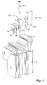
- Fig. 2 is shown in perspective view, the cuff 10 and the screw 20 before placing in the upper corner of the inactive leaf with forend 1 and sash profile 2. It can be seen that the forend profile 1 in the miter area was welded to the upper horizontal sash profile 2.
- the previously correspondingly trimmed forend or sash profiles 1, 2 form after the welding of the profiles an open, formed by two flat, mutually perpendicular cut surfaces corner. This open corner area is closed by the cuff cap 1.
- a PVC adhesive is applied before placing the cuff cap, which, however, requires a certain period of time until curing.
- Fig. 3 is in perspective view the underside of the cuff 10 with the protruding clamping elements 11, 12, 14, 15 and 16 and the dowel-like spreadable clamping element 13 is shown. In this view, the substantially flat base surface 18 is clearly visible.
- Fig. 4 the corner region of the inactive leaf with attached cuff cap 10 and screw 20 is shown.
Landscapes
- Engineering & Computer Science (AREA)
- Civil Engineering (AREA)
- Structural Engineering (AREA)
- Securing Of Glass Panes Or The Like (AREA)
Description
- Die Erfindung betrifft ein System zur Herstellung eines Stulpfensters oder einer Stulptür mit einem Stulpprofil und einer Stulpendkappe zum Verschließen des offenen Endes des Stulpprofils.
- Stulpfenster bzw. -türen sind Fenster bzw. Türen mit wenigstens zwei Flügeln ohne zwischenliegenden, vertikal verlaufenden Pfosten. Der zuerst zu öffnende Flügel, der sog. Gehflügel, schlägt beim Schließen dabei an den anderen, den sog. Lüftungs- oder Standflügel, an. Soweit im folgenden vereinfacht der Begriff Fenster bzw. Stulpfenster verwendet wird, sind damit auch Türen bzw. Stulptüren gemeint.
- Im Stulpbereich wird beim Standflügel zur Bildung des Anschlages für den Gehflügel üblicherweise ein sogenanntes Stulpprofil verwendet, das entweder mit einem gegebenenfalls beschnittenen Flügelrahmenprofil kombiniert wird oder selbst mit dem oberen und dem unteren horizontal verlaufenden Flügelrahmenprofil verschweißt wird. In jedem Fall sind die Hohlkammern des Stulpprofils an seinen beiden Enden offen und werden üblicherweise durch eine Stulpendkappe verschlossen. Die Stulpendkappe übernimmt dabei in der Regel weiterhin die Aufgabe, die Kontur des oberen und unteren horizontal verlaufenden Flügelrahmenprofils des Standflügels bis in den Stulpbereich fortzusetzen.
- Stulpendkappen werden üblicherweise gegenüber dem Ende des Stulpprofils z. B. mit PVC-Kleber verklebt oder mit Silikon abgedichtet und dabei mit diesem verklebt. Zumindest bis zum Abbinden oder Aushärten des Klebers muss die Stulpendkappe aber mechanisch am Stulpprofil fixiert werden.
- Aus der
EP 0 502 354 B1 ist eine gattungsgemäße Stulpendkappe bekannt, die über die Basisfläche vorspringende Klemmvorsprünge aufweist, die in die Hohlkammern des Stulpprofils einführbar sind und hierdurch eine klemmende Befestigung der Stulpendkappe am Stulpprofil ermöglichen. Diese Art der klemmenden Befestigung setzt die Einhaltung enger Toleranzen der Innenmaße der Hohlkammern der Hohlprofile voraus. - Insbesondere bei Systemen, die mit unterschiedlichen Wandstärken vertrieben werden und die somit unterschiedliche Maße der Innenkammern aufweisen, ist eine lediglich durch die Federwirkung der Klemmvorsprünge zu bewirkende Befestigung nicht immer ausreichend.
- Aus der
EP 1 947 283 A2 ist eine Stulpendkappe bekannt, bei der zur Montage Schrauben eingesetzt werden, die in spezielle Schraubkanäle der angrenzenden Profile, nämlich des Stulpprofils und des senkrecht dazu verlaufenden Flügelrahmenprofils, eingeschraubt werden. Hierzu müssen die entsprechenden Hohlprofile jedoch spezielle Schraubkanäle aufweisen, die einen erheblichen Mehraufwand bei der Extrusion bedingen. - Eine ähnliche Ausführungsform zeigt die
DE 20 2008 003 931 U1 , bei der ebenfalls eine Öffnung zur Einführung einer Schraube vorhanden ist, die in den nicht dargestellten Profilleisten mechanisch einführbar ist, womit offenbar ebenfalls spezielle Schraubkanäle gemeint sein könnten. - Aus der
EP 2 014 861 A1 ist ein System zur Herstellung eines Stulpfensters oder einer Stulptür offenbart, welches alle Merkmale des Oberbegriffs des unabhängigen Anspruchs 1 umfasst. - Aufgabe der vorliegenden Erfindung ist es, ein System zur Herstellung eines Stulpfensters oder einer Stulptür, umfassend ein Stulpprofil und eine Stulpendkappe zum Verschließen des offenen Endes des Stulpprofils zur Verfügung zu stellen, wobei die Stulpendkappe auch bei ungünstigen Toleranzen der Innenmaße der Hohlkammern des Stulpfensters und bei Stulpprofilen ohne spezielle Schraubkanäle sicher gehalten wird.
- Die Erfindung löst diese Aufgabe durch ein System nach Anspruch 1, bevorzugt in Verbindung mit einem oder mehreren Merkmalen der Unteransprüche.
- Die Erfindung betrifft daher insbesondere ein System zur Herstellung eines Stulpfensters oder einer Stulptür, umfassend ein Stulpprofil und eine Stulpendkappe zum Verschließen des offenen Endes des Stulpprofils, wobei die Stulpendkappe eine der Kontur des offenen Endes des Stulpprofils angepasste Basisfläche und mehrere aus der Basisfläche hervorragende Klemmelemente aufweist, die in die offenen Hohlkammern des Stulpprofils einführbar sind, und wobei wenigstens eines der Klemmelemente als ein Spreizelement ausgeführt ist, das durch Relativbewegung eines Betätigungsmittels spreizbar ist.
- Nach einer besonders bevorzugten Ausführungsform der Erfindung ist das Spreizelement einstückig mit der Stulpendkappe verbunden und weist etwa die Form eines Dübels auf. Als Betätigungsmittel wird bevorzugt eine Schraube oder einen Stift verwendet, der beim Einführen in das Spreizelement dieses aufspreizt. Das Spreizelement wird zweckmäßig so dimensioniert, dass es im ungespreizten Zustand leicht in eine der Hohlkammern des Stulpprofils einführbar ist und beim Spreizen wie ein Dübel gegen die Wandungen des Stulpprofils gepresst wird.
- Die erfindungsgemäß eingesetzte Stulpendkappe wird bevorzugt - wie im Stand der Technik üblich - im Spritzgussverfahren aus Kunststoff, insbesondere aus PVC, hergestellt. Sie weist nach einer besonders bevorzugten Ausführungsform der Erfindung eine im Wesentlichen ebene Basisfläche auf. Dementsprechend weist das Stulpprofil an seinen offenen Enden ebenfalls eine im Wesentlichen ebene Schnittfläche auf. Bevorzugt wird die Stulpendkappe beispielsweise mittels eines PVC-Klebers dichtend mit dem Ende des Stulpprofils verklebt. Die dübelartige Verbindung der Stulpendkappe mit dem Stulpprofil dient daher im Wesentlichen dazu, die Stulpendkappe bis zum Aushärten des Klebers zu fixieren.
- Die Erfindung wird nachfolgend anhand eines Ausführungsbeispiels sowie der Zeichnung näher erläutert. Es zeigen dabei:
- Fig. 1
- einen Querschnitt durch den Stulpbereich eines Stulpfensters
- Fig. 2
- eine perspektivische Ansicht des oberen Bereichs des Standflügels vor dem Aufsetzen der Stulpendkappe;
- Fig. 3
- eine perspektivische Ansicht der Stulpendkappe von der Unterseite;
- Fig. 4
- eine perspektivische Ansicht des Stulpbereichs des Standflügels mit aufgesetzter Stulpendkappe.
- In dem in
Fig. 1 im Querschnitt dargestellten Stulpbereich des Stulpfensters ist rechts das Stulpprofil 1 mit Glasfalzbereich 5 und Glasleiste 4 dargestellt. Das Stulpprofil 1 dient als Anschlag für das Flügelrahmenprofil 2, das ebenfalls einen Glasfalzbereich 6 und eine Glasleiste 3 aufweist. InFig. 1 ist zu erkennen, dass die Klemmelemente 11, 12, 14, 15 und 16 der aufgesetzten Stulpendkappe 10 klemmend in die Hohlkammern 9 des Stulpprofils 1 eingreifen. Die Außensichtfläche ist mit Bezugszeichen 7, die Innensichtfläche mit Bezugszeichen 8 gekennzeichnet. - Das Klemmelement 13 ist, wie ebenfalls in
Fig. 1 zu erkennen, wie ein Dübel mit mittigem Spreizschlitz 19 und Loch bzw. Bohrung 17 ausgebildet. Durch das Loch 17 wird die Schraube 20 eingeschraubt, wodurch das Klemmelement 13 gespreizt und gegen die angrenzenden Innenwandungen der Hohlkammer 9 des Stulpprofils 1 gepresst wird. - In
Fig. 2 ist in perspektivische Ansicht die Stulpendkappe 10 sowie die Schraube 20 vor dem Aufsetzen in den oberen Eckbereich des Standflügels mit Stulpprofil 1 und Flügelrahmenprofil 2 dargestellt. Man erkennt, dass das Stulpprofil 1 im Gehrungsbereich mit dem oberen horizontalen Flügelrahmenprofil 2 verschweißt wurde. Die vorher entsprechend beschnittenen Stulp- bzw. Flügelrahmenprofile 1, 2 bilden nach dem Verschweißen der Profile einen offenen, durch zwei ebene, senkrecht zueinander verlaufende Schnittflächen gebildeten Eckbereich. Dieser offene Eckbereich wird durch die Stulpendkappe 1 verschlossen. Zur Abdichtung des offenen Eckbereichs wird vor dem Aufsetzen der Stulpendkappe 10 ein PVC-Kleber aufgetragen, der allerdings einen gewissen Zeitraum bis zum Aushärten benötigt. - In
Fig. 3 ist in perspektivische Ansicht die Unterseite der Stulpendkappe 10 mit den herausragenden Klemmelementen 11, 12, 14, 15 und 16 sowie dem dübelartig ausgebildeten spreizbaren Klemmelement 13 dargestellt. In dieser Ansicht ist die im Wesentlichen ebene Basisfläche 18 gut zu erkennen. - In
Fig. 4 ist der Eckbereich des Standflügels mit aufgesetzter Stulpendkappe 10 und Schraube 20 dargestellt. -
- 1.
- Stulpprofil
- 2.
- Flügelrahmenprofil
- 3.
- Glasleiste
- 4.
- Glasleiste
- 5.
- Glasfalzbereich
- 6.
- Glasfalzbereich
- 7.
- Außensichtfläche
- 8.
- Innensichtfläche
- 9.
- Hohlkammern
- 10.
- Stulpendkappe
- 11.
- Klemmelement
- 12.
- Klemmelement
- 13.
- Klemmelement (spreizbar)
- 14.
- Klemmelement
- 15.
- Klemmelement
- 16.
- Klemmelement
- 17.
- Loch/Bohrung
- 18.
- Basisfläche
- 19.
- Spreizschlitz
- 20.
- Schraube
Claims (4)
- System zur Herstellung eines Stulpfensters oder einer Stulptür, umfassend ein Stulpprofil (15) und eine Stulpendkappe (10) zum Verschließen des offenen Endes des Stulpprofils (15), wobei die Stulpendkappe (10) eine der Kontur des offenen Endes des Stulpprofils (15) angepasste Basisfläche (18) und mehrere aus der Basisfläche (18) hervorragende Klemmelemente (11-16) aufweist, die in die offenen Hohlkammern (9) des Stulpprofils (15) einführbar sind, dadurch gekennzeichnet, dass wenigstens eines der Klemmelemente (11-16) als ein Spreizelement (13) ausgeführt ist, das durch Relativbewegung eines Betätigungsmittels (20) spreizbar ist.
- System nach Anspruch 1, dadurch gekennzeichnet dass die Stulpendkappe (10) im Spritzgussverfahren hergestellt ist.
- System nach Anspruch 1 oder 2, dadurch gekennzeichnet dass das Spreizelement (13) der Stulpendkappe (10) einstückig mit der Stulpendkappe (10) verbunden ist und die Form eines Dübels aufweist, der durch Einführen einer Schraube (20), eines Stiftes o. dgl. gespreizt werden kann.
- System nach einem der Ansprüche 1 bis 3, dadurch gekennzeichnet, dass die Stulpendkappe (10) eine im Wesentlichen ebene Basisfläche (18) aufweist.
Priority Applications (1)
| Application Number | Priority Date | Filing Date | Title |
|---|---|---|---|
| EP12710728.2A EP2689086B1 (de) | 2011-03-24 | 2012-03-26 | System zur herstellung eines stulpfensters |
Applications Claiming Priority (3)
| Application Number | Priority Date | Filing Date | Title |
|---|---|---|---|
| EP11159676A EP2503089A1 (de) | 2011-03-24 | 2011-03-24 | System zur Herstellung eines Stulpfensters sowie Stulpendkappe hierfür |
| PCT/EP2012/055329 WO2012127059A1 (de) | 2011-03-24 | 2012-03-26 | System zur herstellung eines stulpfensters |
| EP12710728.2A EP2689086B1 (de) | 2011-03-24 | 2012-03-26 | System zur herstellung eines stulpfensters |
Publications (2)
| Publication Number | Publication Date |
|---|---|
| EP2689086A1 EP2689086A1 (de) | 2014-01-29 |
| EP2689086B1 true EP2689086B1 (de) | 2014-10-08 |
Family
ID=45888221
Family Applications (2)
| Application Number | Title | Priority Date | Filing Date |
|---|---|---|---|
| EP11159676A Withdrawn EP2503089A1 (de) | 2011-03-24 | 2011-03-24 | System zur Herstellung eines Stulpfensters sowie Stulpendkappe hierfür |
| EP12710728.2A Active EP2689086B1 (de) | 2011-03-24 | 2012-03-26 | System zur herstellung eines stulpfensters |
Family Applications Before (1)
| Application Number | Title | Priority Date | Filing Date |
|---|---|---|---|
| EP11159676A Withdrawn EP2503089A1 (de) | 2011-03-24 | 2011-03-24 | System zur Herstellung eines Stulpfensters sowie Stulpendkappe hierfür |
Country Status (2)
| Country | Link |
|---|---|
| EP (2) | EP2503089A1 (de) |
| WO (1) | WO2012127059A1 (de) |
Cited By (2)
| Publication number | Priority date | Publication date | Assignee | Title |
|---|---|---|---|---|
| EP3190255A1 (de) | 2016-01-08 | 2017-07-12 | Profine GmbH | Endkappe und deren verwendung |
| DE102017100293A1 (de) | 2016-01-08 | 2017-07-13 | Profine Gmbh | Endkappe und deren Verwendung |
Families Citing this family (4)
| Publication number | Priority date | Publication date | Assignee | Title |
|---|---|---|---|---|
| CN104005674B (zh) * | 2014-04-30 | 2015-12-16 | 安徽省家好家节能门窗有限公司 | 一种美式手摇外平开窗 |
| JP6344080B2 (ja) * | 2014-06-19 | 2018-06-20 | トヨタ自動車株式会社 | 内燃機関の制御装置 |
| FR3031147B1 (fr) * | 2014-12-29 | 2017-07-21 | Lapeyre | Jonction de deux elements profiles de largeurs differentes |
| CN107269161A (zh) * | 2017-01-12 | 2017-10-20 | 山东凯米特铝业有限公司 | 防雾霾手摇平开新风空气净化系统组合窗 |
Family Cites Families (5)
| Publication number | Priority date | Publication date | Assignee | Title |
|---|---|---|---|---|
| DE9102714U1 (de) | 1991-03-07 | 1991-06-06 | Niemann, Hans Dieter, 5014 Kerpen | Endkappe zum Verschließen eines Hohlprofilstabs von Fenstern, Türen o.dgl. |
| DE29516953U1 (de) * | 1995-10-26 | 1995-12-21 | Rehau Ag + Co, 95111 Rehau | Endkappe für Wandanschlußprofil |
| EP1947283B1 (de) | 2007-01-22 | 2016-04-13 | swisswindows AG | Fenster- oder Türflügel und Verfahren zu dessen Herstellung |
| ES2333058T3 (es) * | 2007-07-10 | 2010-02-16 | Alcoa Aluminium Deutschland, Inc. | Elemento de entanqueizacion y sistem de marco de ventana/ de puerta con un elemento de estanqueizacion. |
| DE202008003931U1 (de) | 2008-03-20 | 2009-07-30 | Rehau Ag + Co | Endkappe |
-
2011
- 2011-03-24 EP EP11159676A patent/EP2503089A1/de not_active Withdrawn
-
2012
- 2012-03-26 WO PCT/EP2012/055329 patent/WO2012127059A1/de not_active Ceased
- 2012-03-26 EP EP12710728.2A patent/EP2689086B1/de active Active
Cited By (2)
| Publication number | Priority date | Publication date | Assignee | Title |
|---|---|---|---|---|
| EP3190255A1 (de) | 2016-01-08 | 2017-07-12 | Profine GmbH | Endkappe und deren verwendung |
| DE102017100293A1 (de) | 2016-01-08 | 2017-07-13 | Profine Gmbh | Endkappe und deren Verwendung |
Also Published As
| Publication number | Publication date |
|---|---|
| WO2012127059A1 (de) | 2012-09-27 |
| EP2503089A1 (de) | 2012-09-26 |
| EP2689086A1 (de) | 2014-01-29 |
Similar Documents
| Publication | Publication Date | Title |
|---|---|---|
| EP2689086B1 (de) | System zur herstellung eines stulpfensters | |
| DE102012108931A1 (de) | Verfahren zum Herstellen eines Gebäudetür-Türblatts sowie damit herstellbares Türblatt | |
| DE29916942U1 (de) | Verbundfenster | |
| DE102012010028A1 (de) | Rahmenanordnung für ein sektionaltorpaneel | |
| DE202010003212U1 (de) | Rahmen eines Kunststofffensters oder einer Kunststofftür sowie Mitteldichtung hierfür | |
| CH706319B1 (de) | Fenster. | |
| EP3187677A1 (de) | Verfahren zur herstellung eines stulpfensters | |
| DE3934265A1 (de) | Gebaeude-bauteil, insbesondere fenster, tuer od. dgl. und verfahren zu seiner herstellung | |
| DE202008011056U1 (de) | Gebäudefenster oder Gebäudetür sowie Stulpausgleichsteil zur Verwendung bei einem Gebäudefenster oder einer Gebäudetür | |
| DE102008054921A1 (de) | Fenster mit Blend- und Flügelrahmen | |
| EP3190255B1 (de) | Endkappe und deren verwendung | |
| AT518200A2 (de) | Kombi-Glashalter und damit ausgerüstetes Holz-Alu-Verbundfenster | |
| DE2621489A1 (de) | Fenster oder tuere mit einer scheibe, insbesondere einer isolierglasdoppelscheibe und/oder einer fuellung | |
| DE9214208U1 (de) | Fenstereinheit | |
| DE10251431A1 (de) | Haustür | |
| DE102012212551A1 (de) | Dämmplatte für Fensterlaibungen | |
| DE102011103196A1 (de) | Fensterelement | |
| DE3513466C2 (de) | ||
| DE102006062161A1 (de) | Kunststoff-Profilsystem für ein Fenster oder eine Tür | |
| DE4234435A1 (de) | Bausatz zur Bildung von Verglasungsrahmen für Fenster, Lichtbänder o. dgl. | |
| DE2026947A1 (de) | Metallkonstruktion, insbesondere zum Herstellen von Einsatzen, Befestigungen u dgl in Gebäuden | |
| DE102016107949A1 (de) | Profilrahmen für eine Tür, ein Fenster oder dgl. sowie ein Verfahren zur Herstellung eines derartigen Profilrahmens | |
| DE102016102606A1 (de) | Profil für Fenster- und Türrahmen | |
| DE202016100768U1 (de) | Profil für Fenster- und Türrahmen | |
| DE3720995A1 (de) | Vorsatzrahmen |
Legal Events
| Date | Code | Title | Description |
|---|---|---|---|
| PUAI | Public reference made under article 153(3) epc to a published international application that has entered the european phase |
Free format text: ORIGINAL CODE: 0009012 |
|
| 17P | Request for examination filed |
Effective date: 20131024 |
|
| AK | Designated contracting states |
Kind code of ref document: A1 Designated state(s): AL AT BE BG CH CY CZ DE DK EE ES FI FR GB GR HR HU IE IS IT LI LT LU LV MC MK MT NL NO PL PT RO RS SE SI SK SM TR |
|
| AX | Request for extension of the european patent |
Extension state: BA ME |
|
| GRAP | Despatch of communication of intention to grant a patent |
Free format text: ORIGINAL CODE: EPIDOSNIGR1 |
|
| RIC1 | Information provided on ipc code assigned before grant |
Ipc: E06B 3/36 20060101AFI20140630BHEP Ipc: E06B 3/964 20060101ALI20140630BHEP |
|
| INTG | Intention to grant announced |
Effective date: 20140714 |
|
| GRAS | Grant fee paid |
Free format text: ORIGINAL CODE: EPIDOSNIGR3 |
|
| GRAA | (expected) grant |
Free format text: ORIGINAL CODE: 0009210 |
|
| AK | Designated contracting states |
Kind code of ref document: B1 Designated state(s): AL AT BE BG CH CY CZ DE DK EE ES FI FR GB GR HR HU IE IS IT LI LT LU LV MC MK MT NL NO PL PT RO RS SE SI SK SM TR |
|
| AX | Request for extension of the european patent |
Extension state: BA ME |
|
| REG | Reference to a national code |
Ref country code: GB Ref legal event code: FG4D Free format text: NOT ENGLISH |
|
| REG | Reference to a national code |
Ref country code: CH Ref legal event code: EP Ref country code: AT Ref legal event code: REF Ref document number: 690740 Country of ref document: AT Kind code of ref document: T Effective date: 20141015 |
|
| REG | Reference to a national code |
Ref country code: IE Ref legal event code: FG4D Free format text: LANGUAGE OF EP DOCUMENT: GERMAN |
|
| REG | Reference to a national code |
Ref country code: DE Ref legal event code: R096 Ref document number: 502012001396 Country of ref document: DE Effective date: 20141120 |
|
| REG | Reference to a national code |
Ref country code: NL Ref legal event code: VDEP Effective date: 20141008 |
|
| REG | Reference to a national code |
Ref country code: FR Ref legal event code: PLFP Year of fee payment: 4 |
|
| REG | Reference to a national code |
Ref country code: LT Ref legal event code: MG4D |
|
| PG25 | Lapsed in a contracting state [announced via postgrant information from national office to epo] |
Ref country code: NL Free format text: LAPSE BECAUSE OF FAILURE TO SUBMIT A TRANSLATION OF THE DESCRIPTION OR TO PAY THE FEE WITHIN THE PRESCRIBED TIME-LIMIT Effective date: 20141008 |
|
| PG25 | Lapsed in a contracting state [announced via postgrant information from national office to epo] |
Ref country code: ES Free format text: LAPSE BECAUSE OF FAILURE TO SUBMIT A TRANSLATION OF THE DESCRIPTION OR TO PAY THE FEE WITHIN THE PRESCRIBED TIME-LIMIT Effective date: 20141008 Ref country code: LT Free format text: LAPSE BECAUSE OF FAILURE TO SUBMIT A TRANSLATION OF THE DESCRIPTION OR TO PAY THE FEE WITHIN THE PRESCRIBED TIME-LIMIT Effective date: 20141008 Ref country code: IS Free format text: LAPSE BECAUSE OF FAILURE TO SUBMIT A TRANSLATION OF THE DESCRIPTION OR TO PAY THE FEE WITHIN THE PRESCRIBED TIME-LIMIT Effective date: 20150208 Ref country code: FI Free format text: LAPSE BECAUSE OF FAILURE TO SUBMIT A TRANSLATION OF THE DESCRIPTION OR TO PAY THE FEE WITHIN THE PRESCRIBED TIME-LIMIT Effective date: 20141008 Ref country code: NO Free format text: LAPSE BECAUSE OF FAILURE TO SUBMIT A TRANSLATION OF THE DESCRIPTION OR TO PAY THE FEE WITHIN THE PRESCRIBED TIME-LIMIT Effective date: 20150108 Ref country code: PT Free format text: LAPSE BECAUSE OF FAILURE TO SUBMIT A TRANSLATION OF THE DESCRIPTION OR TO PAY THE FEE WITHIN THE PRESCRIBED TIME-LIMIT Effective date: 20150209 |
|
| PG25 | Lapsed in a contracting state [announced via postgrant information from national office to epo] |
Ref country code: RS Free format text: LAPSE BECAUSE OF FAILURE TO SUBMIT A TRANSLATION OF THE DESCRIPTION OR TO PAY THE FEE WITHIN THE PRESCRIBED TIME-LIMIT Effective date: 20141008 Ref country code: PL Free format text: LAPSE BECAUSE OF FAILURE TO SUBMIT A TRANSLATION OF THE DESCRIPTION OR TO PAY THE FEE WITHIN THE PRESCRIBED TIME-LIMIT Effective date: 20141008 Ref country code: SE Free format text: LAPSE BECAUSE OF FAILURE TO SUBMIT A TRANSLATION OF THE DESCRIPTION OR TO PAY THE FEE WITHIN THE PRESCRIBED TIME-LIMIT Effective date: 20141008 Ref country code: GR Free format text: LAPSE BECAUSE OF FAILURE TO SUBMIT A TRANSLATION OF THE DESCRIPTION OR TO PAY THE FEE WITHIN THE PRESCRIBED TIME-LIMIT Effective date: 20150109 Ref country code: CY Free format text: LAPSE BECAUSE OF FAILURE TO SUBMIT A TRANSLATION OF THE DESCRIPTION OR TO PAY THE FEE WITHIN THE PRESCRIBED TIME-LIMIT Effective date: 20141008 Ref country code: LV Free format text: LAPSE BECAUSE OF FAILURE TO SUBMIT A TRANSLATION OF THE DESCRIPTION OR TO PAY THE FEE WITHIN THE PRESCRIBED TIME-LIMIT Effective date: 20141008 Ref country code: HR Free format text: LAPSE BECAUSE OF FAILURE TO SUBMIT A TRANSLATION OF THE DESCRIPTION OR TO PAY THE FEE WITHIN THE PRESCRIBED TIME-LIMIT Effective date: 20141008 |
|
| REG | Reference to a national code |
Ref country code: DE Ref legal event code: R097 Ref document number: 502012001396 Country of ref document: DE |
|
| PG25 | Lapsed in a contracting state [announced via postgrant information from national office to epo] |
Ref country code: DK Free format text: LAPSE BECAUSE OF FAILURE TO SUBMIT A TRANSLATION OF THE DESCRIPTION OR TO PAY THE FEE WITHIN THE PRESCRIBED TIME-LIMIT Effective date: 20141008 Ref country code: CZ Free format text: LAPSE BECAUSE OF FAILURE TO SUBMIT A TRANSLATION OF THE DESCRIPTION OR TO PAY THE FEE WITHIN THE PRESCRIBED TIME-LIMIT Effective date: 20141008 Ref country code: SK Free format text: LAPSE BECAUSE OF FAILURE TO SUBMIT A TRANSLATION OF THE DESCRIPTION OR TO PAY THE FEE WITHIN THE PRESCRIBED TIME-LIMIT Effective date: 20141008 Ref country code: RO Free format text: LAPSE BECAUSE OF FAILURE TO SUBMIT A TRANSLATION OF THE DESCRIPTION OR TO PAY THE FEE WITHIN THE PRESCRIBED TIME-LIMIT Effective date: 20141008 Ref country code: EE Free format text: LAPSE BECAUSE OF FAILURE TO SUBMIT A TRANSLATION OF THE DESCRIPTION OR TO PAY THE FEE WITHIN THE PRESCRIBED TIME-LIMIT Effective date: 20141008 |
|
| PLBE | No opposition filed within time limit |
Free format text: ORIGINAL CODE: 0009261 |
|
| STAA | Information on the status of an ep patent application or granted ep patent |
Free format text: STATUS: NO OPPOSITION FILED WITHIN TIME LIMIT |
|
| PG25 | Lapsed in a contracting state [announced via postgrant information from national office to epo] |
Ref country code: IT Free format text: LAPSE BECAUSE OF FAILURE TO SUBMIT A TRANSLATION OF THE DESCRIPTION OR TO PAY THE FEE WITHIN THE PRESCRIBED TIME-LIMIT Effective date: 20141008 |
|
| 26N | No opposition filed |
Effective date: 20150709 |
|
| PG25 | Lapsed in a contracting state [announced via postgrant information from national office to epo] |
Ref country code: LU Free format text: LAPSE BECAUSE OF FAILURE TO SUBMIT A TRANSLATION OF THE DESCRIPTION OR TO PAY THE FEE WITHIN THE PRESCRIBED TIME-LIMIT Effective date: 20150326 Ref country code: MC Free format text: LAPSE BECAUSE OF FAILURE TO SUBMIT A TRANSLATION OF THE DESCRIPTION OR TO PAY THE FEE WITHIN THE PRESCRIBED TIME-LIMIT Effective date: 20141008 |
|
| REG | Reference to a national code |
Ref country code: IE Ref legal event code: MM4A |
|
| PG25 | Lapsed in a contracting state [announced via postgrant information from national office to epo] |
Ref country code: IE Free format text: LAPSE BECAUSE OF NON-PAYMENT OF DUE FEES Effective date: 20150326 |
|
| PG25 | Lapsed in a contracting state [announced via postgrant information from national office to epo] |
Ref country code: SI Free format text: LAPSE BECAUSE OF FAILURE TO SUBMIT A TRANSLATION OF THE DESCRIPTION OR TO PAY THE FEE WITHIN THE PRESCRIBED TIME-LIMIT Effective date: 20141008 |
|
| REG | Reference to a national code |
Ref country code: FR Ref legal event code: PLFP Year of fee payment: 5 |
|
| GBPC | Gb: european patent ceased through non-payment of renewal fee |
Effective date: 20160326 |
|
| PG25 | Lapsed in a contracting state [announced via postgrant information from national office to epo] |
Ref country code: MT Free format text: LAPSE BECAUSE OF FAILURE TO SUBMIT A TRANSLATION OF THE DESCRIPTION OR TO PAY THE FEE WITHIN THE PRESCRIBED TIME-LIMIT Effective date: 20141008 |
|
| PG25 | Lapsed in a contracting state [announced via postgrant information from national office to epo] |
Ref country code: GB Free format text: LAPSE BECAUSE OF NON-PAYMENT OF DUE FEES Effective date: 20160326 |
|
| REG | Reference to a national code |
Ref country code: FR Ref legal event code: PLFP Year of fee payment: 6 |
|
| PG25 | Lapsed in a contracting state [announced via postgrant information from national office to epo] |
Ref country code: HU Free format text: LAPSE BECAUSE OF FAILURE TO SUBMIT A TRANSLATION OF THE DESCRIPTION OR TO PAY THE FEE WITHIN THE PRESCRIBED TIME-LIMIT; INVALID AB INITIO Effective date: 20120326 Ref country code: BG Free format text: LAPSE BECAUSE OF FAILURE TO SUBMIT A TRANSLATION OF THE DESCRIPTION OR TO PAY THE FEE WITHIN THE PRESCRIBED TIME-LIMIT Effective date: 20141008 Ref country code: SM Free format text: LAPSE BECAUSE OF FAILURE TO SUBMIT A TRANSLATION OF THE DESCRIPTION OR TO PAY THE FEE WITHIN THE PRESCRIBED TIME-LIMIT Effective date: 20141008 |
|
| PG25 | Lapsed in a contracting state [announced via postgrant information from national office to epo] |
Ref country code: BE Free format text: LAPSE BECAUSE OF NON-PAYMENT OF DUE FEES Effective date: 20150331 |
|
| PG25 | Lapsed in a contracting state [announced via postgrant information from national office to epo] |
Ref country code: TR Free format text: LAPSE BECAUSE OF FAILURE TO SUBMIT A TRANSLATION OF THE DESCRIPTION OR TO PAY THE FEE WITHIN THE PRESCRIBED TIME-LIMIT Effective date: 20141008 |
|
| REG | Reference to a national code |
Ref country code: FR Ref legal event code: PLFP Year of fee payment: 7 |
|
| PG25 | Lapsed in a contracting state [announced via postgrant information from national office to epo] |
Ref country code: MK Free format text: LAPSE BECAUSE OF FAILURE TO SUBMIT A TRANSLATION OF THE DESCRIPTION OR TO PAY THE FEE WITHIN THE PRESCRIBED TIME-LIMIT Effective date: 20141008 |
|
| PG25 | Lapsed in a contracting state [announced via postgrant information from national office to epo] |
Ref country code: AL Free format text: LAPSE BECAUSE OF FAILURE TO SUBMIT A TRANSLATION OF THE DESCRIPTION OR TO PAY THE FEE WITHIN THE PRESCRIBED TIME-LIMIT Effective date: 20141008 |
|
| REG | Reference to a national code |
Ref country code: DE Ref legal event code: R082 Ref document number: 502012001396 Country of ref document: DE Representative=s name: HOCKER, THOMAS GERHARD, DIPL.-ING., LL.M., DE |
|
| PGFP | Annual fee paid to national office [announced via postgrant information from national office to epo] |
Ref country code: AT Payment date: 20200320 Year of fee payment: 9 |
|
| PGFP | Annual fee paid to national office [announced via postgrant information from national office to epo] |
Ref country code: CH Payment date: 20200319 Year of fee payment: 9 |
|
| PGFP | Annual fee paid to national office [announced via postgrant information from national office to epo] |
Ref country code: FR Payment date: 20200320 Year of fee payment: 9 |
|
| PGFP | Annual fee paid to national office [announced via postgrant information from national office to epo] |
Ref country code: DE Payment date: 20210319 Year of fee payment: 10 |
|
| REG | Reference to a national code |
Ref country code: CH Ref legal event code: PL |
|
| REG | Reference to a national code |
Ref country code: AT Ref legal event code: MM01 Ref document number: 690740 Country of ref document: AT Kind code of ref document: T Effective date: 20210326 |
|
| PG25 | Lapsed in a contracting state [announced via postgrant information from national office to epo] |
Ref country code: AT Free format text: LAPSE BECAUSE OF NON-PAYMENT OF DUE FEES Effective date: 20210326 Ref country code: CH Free format text: LAPSE BECAUSE OF NON-PAYMENT OF DUE FEES Effective date: 20210331 Ref country code: LI Free format text: LAPSE BECAUSE OF NON-PAYMENT OF DUE FEES Effective date: 20210331 Ref country code: FR Free format text: LAPSE BECAUSE OF NON-PAYMENT OF DUE FEES Effective date: 20210331 |
|
| REG | Reference to a national code |
Ref country code: DE Ref legal event code: R119 Ref document number: 502012001396 Country of ref document: DE |
|
| PG25 | Lapsed in a contracting state [announced via postgrant information from national office to epo] |
Ref country code: DE Free format text: LAPSE BECAUSE OF NON-PAYMENT OF DUE FEES Effective date: 20221001 |