EP2689663A2 - Dispositif de portionnement et de travail avec segment de positionnement interchangeable - Google Patents
Dispositif de portionnement et de travail avec segment de positionnement interchangeable Download PDFInfo
- Publication number
- EP2689663A2 EP2689663A2 EP13176517.4A EP13176517A EP2689663A2 EP 2689663 A2 EP2689663 A2 EP 2689663A2 EP 13176517 A EP13176517 A EP 13176517A EP 2689663 A2 EP2689663 A2 EP 2689663A2
- Authority
- EP
- European Patent Office
- Prior art keywords
- portioning
- segment
- locking
- portioniersegment
- portioning segment
- Prior art date
- Legal status (The legal status is an assumption and is not a legal conclusion. Google has not performed a legal analysis and makes no representation as to the accuracy of the status listed.)
- Granted
Links
- 238000009434 installation Methods 0.000 claims abstract description 32
- 230000002093 peripheral effect Effects 0.000 claims abstract description 29
- 238000004898 kneading Methods 0.000 claims abstract description 7
- 238000006073 displacement reaction Methods 0.000 claims abstract description 4
- 230000033001 locomotion Effects 0.000 claims description 30
- 238000009940 knitting Methods 0.000 claims description 15
- 238000003780 insertion Methods 0.000 claims description 4
- 230000037431 insertion Effects 0.000 claims description 4
- 239000002245 particle Substances 0.000 claims 1
- 230000007246 mechanism Effects 0.000 description 4
- 230000008878 coupling Effects 0.000 description 3
- 238000010168 coupling process Methods 0.000 description 3
- 238000005859 coupling reaction Methods 0.000 description 3
- 230000005540 biological transmission Effects 0.000 description 2
- 150000001875 compounds Chemical class 0.000 description 2
- 230000003670 easy-to-clean Effects 0.000 description 2
- 238000004519 manufacturing process Methods 0.000 description 2
- 230000015572 biosynthetic process Effects 0.000 description 1
- 239000000969 carrier Substances 0.000 description 1
- 238000004140 cleaning Methods 0.000 description 1
- 238000010276 construction Methods 0.000 description 1
- 230000002349 favourable effect Effects 0.000 description 1
- 239000002184 metal Substances 0.000 description 1
- 238000000034 method Methods 0.000 description 1
- 230000008569 process Effects 0.000 description 1
- 230000008439 repair process Effects 0.000 description 1
- 230000035939 shock Effects 0.000 description 1
- 238000005303 weighing Methods 0.000 description 1
Images






Classifications
-
- A—HUMAN NECESSITIES
- A21—BAKING; EDIBLE DOUGHS
- A21C—MACHINES OR EQUIPMENT FOR MAKING OR PROCESSING DOUGHS; HANDLING BAKED ARTICLES MADE FROM DOUGH
- A21C5/00—Dough-dividing machines
- A21C5/02—Dough-dividing machines with division boxes and ejection plungers
- A21C5/04—Dough-dividing machines with division boxes and ejection plungers with division boxes in a revolving body with radially-working pistons
-
- A—HUMAN NECESSITIES
- A21—BAKING; EDIBLE DOUGHS
- A21C—MACHINES OR EQUIPMENT FOR MAKING OR PROCESSING DOUGHS; HANDLING BAKED ARTICLES MADE FROM DOUGH
- A21C7/00—Machines which homogenise the subdivided dough by working other than by kneading
- A21C7/005—Machines which homogenise the subdivided dough by working other than by kneading the dough pieces being worked in radially disposed cavities in a rotating drum
Definitions
- the present invention relates to a portioning and processing device for producing Teigteilchen, with a drum-shaped Teigteilhuntudi, wherein at an outer peripheral portion of the drum-shaped Teigteiltalkformats at least one Portioniersegment interchangeable fastened, wherein the Portioniersegment at least one, preferably a plurality of measuring chambers with a reciprocable therein Has measuring piston.
- Such portioning and effecting devices are known and usually serve for portioning dough and for producing individual Teigteilchen or dough pieces.
- the document DE 10 2006 018 626 A1 describes a portioning unit as a unit of a dough dividing knitting machine with a sub-drum, in which at least one radially arranged part of cylinder to the outer surface of the drum open is arranged, in which a partial piston is radially movable, wherein all lying axially on a surface line cylinder part of the sub-drum are combined to form a cylinder bar and the cylinder strips are removed in the radial direction of the sub-drum.
- advantages of the solution set out in this document are mentioned that in a cleaning or repair only a few cylinder strips instead of many individual sub-cylinders must be removed and installed, and that with a radial removal of the cylinder strips required for the expansion space can be reduced.
- a part cylinder which can be removed in the radial direction requires a great deal of precision during installation, since the part cylinder must be set and pushed in at a specific position. In this document, no drive of the sub-cylinders is disclosed in the radial direction.
- the document describes DE 24 38 316 C2 a machine for dividing and working pieces of dough, comprising a frame in which a drum with at least three rows of measuring chambers uniformly distributed around its circumference is rotatably mounted on a drum axis.
- An active device with a kneading tool is assigned to one of the measuring chamber rows distributed around the circumference of the drum.
- a measuring piston connected to a guide member is slidably mounted back and forth and the guide members are guided in a path arranged outside the drum.
- the present invention provides a portioning and effecting device of the aforementioned type, which is characterized in that the portioning segment can be brought into an intermediate installation position on the Teigteilschreibussi and can be brought from the intermediate mounting position in a locking position on the Teigteilschreibussi, wherein the portioning and Actuation device a drive device for the Portioniersegment wherein the Portioniersegment operatively coupled by the displacement of the Portioniersegments from the intermediate mounting position in the locking position to the drive device.
- the portioning segment can only be brought into an intermediate installation position, from which it can be pushed further into a locking position.
- the Portioniersegment can be prepositioned in the intermediate mounting position on the Teigteilhuntanii, which facilitates the coupling to the drive means.
- the coupling can be achieved in a simple manner by the displacement in the locking position.
- the Portioniersegment by movement in the radial direction in an intermediate mounting position on the Teigteilschreiba can be brought and displaced from the intermediate mounting position by a movement in the axial direction in a locking position on the Teigteilschreiba.
- the portioning segment can be brought in the radial direction from the outside into an intermediate installation position, from which it can be pushed further into a locking position.
- a kind of bayonet closure is advantageously formed by means of which the portioning segment can be easily and securely fixed to the Teigteilzigla.
- the portioning segment has at least one measuring chamber (or portioning chamber) with a volumetric flask (or portioning flask) which can be moved back and forth, wherein the volumetric flask can be driven by the drive device, preferably positively guided.
- Such an embodiment of the invention allows the volumetric flask to move forcibly back and forth within the measuring chamber.
- the portioned dough pieces can be positioned in the measuring chamber such that they can be knitted with a knitting device engaging at a defined position, for example an active plate.
- the Teigteilzigmoid on a movable by the drive device Traverse and the Portioniersegment has a measuring piston on which at least one, preferably all, measuring piston of the Portioniersegments is fixed, the measuring piston is set in the locking position on the cross member and during a movement of the traverse is moved with this.
- the measuring piston strip can thus be easily coupled to the drive for the volumetric flasks.
- the drive for the volumetric flasks is automatically coupled when installing the portioning segment.
- the portioning segment has at least one, in particular attached to the measuring piston strip, locking element, with a preferably at least partially U-shaped profile, which comes with a Spend the Portioniersegments in the intermediate mounting position in Umgriff with a Traverse of Teigteilzigwhis.
- the locking element engages in the intermediate installation position and also in the locking position, the traverse.
- the portioning segment is thus defined advantageously on the crossbar. Lateral play between the traverse and the portioning segment is minimized and the transmission of the movement of the traverse to the portioning segment is optimized.
- the mountability of the Portioniersegments is improved, the locking element is additionally easy to clean.
- the locking element at least partially a funnel-like cross-section, which is formed by a first tab and a second tab, wherein the first and second tab are each formed as bent by a main body of the locking tabs and / or the locking member having locking receptacles, which are preferably formed slot-like and wherein arranged on the crossbar truss bolts are brought into a movement of the portioning segment from the intermediate mounting position into the locking position with the locking receptacles and set the locking element on the crossmember.
- the tabs can be used to prevent assembly or installation errors.
- the portioning segment can not be locked the wrong way round.
- the locking element can be fixed by means of bolts attached to the traverse on this, by the locking member slides self-positioning along the bolt and into the locking position inside.
- a knitting device which can be arranged in the operative position, preferably in twelve o'clock position of Teigteilzigongs immediately adjacent to the mounted Portioniersegment, wherein the one or more volumetric flasks are positioned in operative position so that the or in the or the measuring chambers located dough pieces are positioned so that they can be knitted by the knitting device.
- portioning segment can be attached to the Teigteilschreibmoi and adjusted so that the positioning effort for the knitting device is minimized.
- fastening elements are arranged and formed on the dough part-chamber carrier and the portioning segment such that fastening elements arranged on the portioning segment thus interact with fastening elements arranged on the dough-part chamber carrier in that the portioning segment can be positioned on the dough compartment carrier in the intermediate installation position and is displaceable from the intermediate installation position into the locking position.
- the Teigteilzigzig comprises at least one designed as a resilient pressure element fastener which is positioned so that it can exert a compressive force substantially perpendicular to the axial direction and wherein the Portioniersegment comprises at least one attachment shoulder, which is arranged on the Portioniersegment in that the mounting shoulder is positioned in the intermediate mounting position of the portioning segment to the resilient thrust piece such that no pressure force is transmitted from the resilient thrust piece to the mounting shoulder and / or wherein a compressive force from the resilient thrust piece upon movement from the intermediate mounting position to the locking position Fixing shoulder is transmitted and / or wherein the fastening shoulder is positioned in the locking position of the portioning segment to the resilient pressure piece that a pressure force from the resilient pressure piece is transferred to the attachment shoulder.
- the Portioniersegment can be clamped, for example, in the locking position by the pressure force or alternatively, provide, for example, with the provision of an additional recess in the locking position, a kind of additional positive locking available. Furthermore, the insertion of the portioning segment is also facilitated, since the insertion openings are provided on the portioning segment and the resilient pressure pieces can be easily inserted into this.
- fastening elements have at least one bolt and at least one second receiving opening associated with the bolt, the second receiving opening being a keyhole-shaped receiving opening and the bolt being arranged in the widened region of the keyhole-shaped receiving opening in the intermediate installation position of the portioning segment and the bolt is disposed in a locking position of the portioning segment on the dough compartment holder in a narrowed portion of the keyhole receiving opening.
- the cooperation of the bolt and keyhole-shaped receiving opening allows a favorable movement of the portioning segment from the intermediate installation position into the locking position. Due to the keyhole shape, the bolt can slide from a widened into a narrowed region of the receiving opening, so that the portioning segment is transferred from a less clearly defined intermediate installation position into a very clearly defined locking position. In addition, the pin can clamp in the narrowed region, so that thereby already the Portioniersegment is frictionally fixed in the locking position.
- the attachment shoulder is spaced from the attachment portion and forms with this a recess in which the resilient pressure piece is received when the Portioniersegment is in a locking position.
- At least one locking device is provided by which the portioning segment is locked in the locking position on the Teigteilzigza, in particular so, in that the main body and the outer peripheral body are immovably fixed to the dough compartment carrier and the volumetric flasks can be moved back and forth at least in the radial direction R.
- the portioning segment can be secured or fixed in its locking position on the dough compartment carrier. At the same time, the mobility of the volumetric flasks is maintained. Thus, an advantageous locking is created, which reliably holds the portioning segment even with rotating Teigteilzigong.
- the portioning segment has at least two longitudinal edges which, at least in sections, in particular over their respective complete length, do not run parallel to one another and / or wherein the portioning segment comprises at least one outer peripheral body which is conically shaped.
- a portioning segment designed in this way can be inserted into a trapezoidal recess, with advantageously only one correct installation position being present.
- the portioning segment can not be inserted the wrong way round.
- a conically shaped Portioniersegment fits well into a drum-shaped Teigteilschreibmoi and is also form-fitting mountable.
- At least two wall elements are fastened to the outer peripheral region of the dough compartment chamber support such that a portioning segment can be fastened between the at least two wall elements, in particular wherein the longitudinal edges of the wall elements are not arranged parallel to one another, so that a portioning segment in a locking direction is slidable between the wall elements until the longitudinal edges of the wall elements are in abutment with the corresponding longitudinal edges of the portioning segment.
- portioning segment is connected to adjacent wall elements, the result is a closed surface of the Teigteilzigys. If the non-parallel longitudinal edges of the portioning segment strike against the longitudinal edges of the wall elements, an end or locking position of the portioning segment for a fitter is clearly achieved.
- an outer peripheral body of at least one Portioniersegments at least one mounting portion rests in an intermediate mounting position and in a locking position of the Portioniersegments on a support shoulder of a segment carrier of Teigteilschreibarris, preferably so that the attachment portion in a movement of the Portioniersegments from the intermediate mounting position slides in the locking position on the support shoulder, wherein preferably between the attachment portion and support shoulder a slide strip is provided.
- connection between Portioniersegment and Teigteilbiblini, or the segment carrier of Teigteilschreiblys advantageously between the attachment portion and the support shoulder.
- the portioning segment is thus secured in the radial direction as well as in the axial direction and can be locked. This ensures stable support of the portioning segment on one or more segment carriers.
- a sliding surface can be provided on which the portioning segment can smoothly and precisely slide from the intermediate installation position to the locking position. The assembly of the portioning segment is thereby further facilitated.
- FIG. 1 shows a portioning and effecting device 1, which comprises a cylindrical or drum-shaped Teigteilformatong 2.
- a portioning and acting device is meant, in particular, a device with which raw mass, such as, for example, dough, can be portioned and, in a following step, the resulting dough pieces can be knitted with a knitting device.
- the wall segments 3 are provided in the outer peripheral region of the Teigteiltalkarris 2 so that between the wall segments 3 Portioniersegmente 8 can be arranged.
- Each of the portioning segments 8 has one or more portioning openings 9, through which dough can be pushed or pushed by a feeding device (not shown) into measuring chambers formed on the portioning segment 8.
- the portioning segments 8 are exchangeable or exchangeable. In this way, the Teigteilhuntanii 2 can be operated variably, in particular with regard to the size and / or shape of the Portionierö réelleen 9 or the size and / or shape of the measuring chambers.
- the Portioniersegmente 8 serve locking lever 10, which secure the Portioniersegmente 8 to the Teigteilhuntanii 2 with later described locking mechanisms.
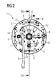
- FIG. 2 shows an end view of a Teigteilhuntumbles 2 with the outer end portion 4 and a support device fixed thereto 5.
- the Teigteilzigzi 2 has a hub 7, which can be connected to a (not shown) shaft to make the Teigteiltalkumble 2 rotationally movable.
- a fixed shaft with bearings may be provided on the Teigteiltalkong 2.
- the Teigteilzigzigza 2 is formed so that four Portioniersegmente 8 can be mounted.
- four locking levers 10 are provided, of which in this view the uppermost in the open position and the further in the closed position.
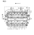
- FIG. 3 shows a sectional view according to FIG. 2 , Parallel to the hub 7, around which the Teigteilzigumble 2 rotates, an axial direction A is defined. Orthogonal to the axial direction A, a radial direction R is defined. Furthermore, a locking direction V is defined.
- Portioning segments 8 are arranged around the Teigteilhunt ashamed 2 around and include a measuring piston 13.
- a plurality of volumetric flasks 11 are fixed with Kolbenfixierettin 15.
- the volumetric flasks 11 can be rigidly fixed in a specific position or can be moved back and forth in the radial direction R with a defined design.
- the volumetric flasks 11 form chamber chambers 16 measuring chambers, wherein the volume of the measuring chambers is variably adjustable by a differently definable positioning of the volumetric flask.
- Each portioning segment 8 has an in FIG. 3 closer to designated main body 8a and an outer peripheral body 8b, within which the Portionierö réelleen 9 are arranged.
- the shape of the portioning segment 8, in particular of the outer peripheral body 8b, is slightly conical.
- the surface of the portioning segment 8 corresponds to the lateral surface of a cone.
- the longitudinal edges 38 of the outer peripheral body 8b are not parallel to each other, that is, they form, seen in two dimensions, a trapezoid with the end edges of the outer peripheral body 8b.
- the wall segments 3 are formed so that the outer peripheral region of the Teigteiltalkarris 2 with mounted wall segments 3 and Portioniersegmenten 8, apart from the Portionierö réelleen 9, forms a closed surface.
- the longitudinal edges 39 of two, one the Portioniersegment 8 receiving space forming, wall segments 3 are also not arranged parallel to each other and form a trapezoid, which is oriented so that the Portioniersegment can be inserted between the two wall segments 3 fitting.
- the portioning and active device 1 may comprise a knitting device 44 known per se.
- the knitting device 44 can be positioned so that a portioning segment 8 located at twelve o'clock position, that is to say in the operative position, is arranged directly adjacent to the knitting device 44.
- the volumetric flasks 11 are first of all brought into such a position that the dough pieces located in the measuring chambers are moved outwards and thus come into contact with a kneading tool 44a of the knitting device 44.
- the movement of the volumetric flask 11 may be determined, for example, by a corresponding design of a control curve 41 to be described later.
- the knitting tool 44 a is set in operative motion and the dough pieces which are in touching contact with the knitting tool 44a are knitted.
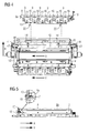
- FIG. 4 shows the Teigteilhuntconstrua 2 as in FIG. 3 in a partially exploded view.
- the upper Portioniersegment 8 is shown in a pre-installation situation.
- the arrangement and attachment of the Portioniersegments on Teigteiltalkong 2 is described below by way of example for a Portioniersegment 8, but may be performed for all on Teigteiltalkarri 2 so.
- the segment carrier 12 has a traverse 42 which projects beyond at least one end section 43 via an outer end region 4 of the portioning device 1.
- a cam roller 40 is arranged, which cooperates with a relative to the segment carrier 12 rotationally fixed control cam 41. If the segment carrier 12 is rotated about its axis of rotation, the end portion 43 is forcibly guided in the control cam 41.
- the traverse 42 is movably mounted within the segment carrier 12 in the radial direction R, so that the positive guidance of the end portion 43 in the control cam 41 has a well-defined movement curve of the traverse 42 in the radial direction R result.
- the cross member 42 describes a precisely defined movement in the radial direction R as a function of the formation of the control cam 41.
- the measuring pistons 11 are therefore forcibly driven back and forth within the measuring chamber. This makes it possible that dough in the measuring chamber in cooperation with an effecting device not only portioned but also can be favorably knitted.
- the portioning segment can therefore be mounted on the segment carrier 12, wherein at the same time the measuring piston strip 13 can be coupled to the drive of the measuring piston strip 13 or the measuring piston 11.
- FIG. 5 in synopsis with FIG. 3 shows that the Portioniersegmente 8, the main body 8A, which includes the chamber walls 16, and the outer peripheral body 8B.
- the portioning segment 8 with main body 8A, outer peripheral body 8B, volumetric flask 11 and measuring piston 13 can be mounted as a whole on the Teigteilzigong 2.
- fastening elements 14 are provided on a segment carrier 12.
- the locking lever 10 is provided in order to set or lock the portioning segment 8 on the Teigteilzigzigza 2, the locking lever 10 is provided.
- FIG. 6 shows a sectional view of the Teigteilzigumbles 2 according to FIG. 1 .
- the Teigteilzigzi 2 has wall segments 3 and Portioniersegmente 8.
- the enlarged detail shows that the segment carrier 12 has a support shoulder 24.
- the support shoulder 24 is provided with second receiving openings 22.
- the second receiving openings 22 may be keyhole-shaped.
- the portioning segment 8 further comprises a fixing portion 8C, to which a spring pin 21 attached, for example, spring-clamped, is.
- the spring pin 21 has at its free end a head which has a larger or wider diameter than the bolt body itself.
- a slide strip 23 is arranged which provides sliding and connecting surfaces on which the portioning segment 8 can slide into an end or operating position or out of the end or operating position.
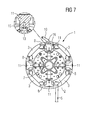
- FIG. 7 shows a sectional view of the Teigteilhuntarris 2 after FIG. 1 , in which measuring chambers are recognizable.
- the measuring chambers are bounded laterally by chamber walls 16 and in the radial direction R by the volumetric flask 11.
- the enlarged detail shows a Kolbenfixierelement 15 for fixing and / or positioning of the volumetric flask 11 on the measuring piston 13.
- FIG. 8 shows the portioning segment 8 is in this view in a position above a recess formed between two wall segments 3 of Teigteiltalkarris 2.
- the Portioniersegment 8 has end walls 27 which are connected to the outer end regions. 4 of Teigteiltalkarris 2 form a compact and closed surface with the state of the portioning segment 1 installed.
- the portioning segment 8 is mounted in the recess by being moved in a first installation step in the radial direction R to the Teigteilhuntanii 2 until the Portioniersegment 8 rests in particular with its main body 8A on the segment carrier 12.
- a sliding strip 23 may be provided between base body 8a and segment carrier 12.
- FIG. 9 and FIG. 10 in this case show the fixing means by means of which the portioning segment 8 can be fixed to the segment carrier 12 or the traverse 42.
- Fastening elements 14 for example spring bolts with a shank 14 a and with a defined head 14 b, are provided on the cross member 42 and the main body 8 a of the portioning segment 8.
- the fastening elements 14 are provided in such a way that they can be brought into the keyhole-shaped second receiving openings 22 in the radial direction R when the portioning segment 8 is moved.
- a front stop 30 and a rear stop 29 are provided which stop a movement of the portioning segment 8 in the locking direction V.
- First receiving openings 17 are provided in the stops 29, 30, in which locking pins 18 oriented in the locking direction V can be received when the portioning segment 8 is moved towards the stops 29, 30.
- the slide strip 23 is attached to the portioning segment 8 and can thus slide on the support shoulder 24.
- a recess 28 is provided in the support shoulder 24, within which at least the head of the fastening element 14 is movable back and forth.
- the recess 28 is formed as a free cut, wherein the fastening element 14 protrudes with its shaft 14a through the second receiving opening 22 and the head 14b of the fastening element 14 can be moved within the recess.
- the portioning segment 8 can be releasably clamped by means of the fastening element 14 on the support shoulder 24, wherein the head 14b rests on a side of the support shoulder 24 facing away from the portioning segment 8.
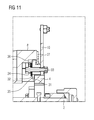
- FIG. 11 shows the locking lever 10 with its locking mechanism, wherein the Portioniersegment 8 is positioned in the locking position on Teigteilschreibla 2.
- the locking lever 10 is rotatably connected to a tightening bolt 33, which in turn rotatably connected to a first locking portion 35 and a second locking portion 36 forming sleeve.
- a tightening bolt 33 which in turn rotatably connected to a first locking portion 35 and a second locking portion 36 forming sleeve.
- the first and the second locking portions 35, 36 are rotated relative to a tightening shoulder 34 provided on an outer end region 4, so that the portioning segment 8 and the dough compartment support 2 are firmly connected to one another in a clamping manner.
- the locking lever 10 is connected via the suit shoulder 34 and a spring element 31 with the first and second latch portion 35, 36, so that acting on the locking mechanism shocks are damped.
- FIG. 12 shows a side view of a Portioniersegments 8 with a measuring piston 13.
- the measuring piston 11 are connected with Kolbenfixier electroden 15 with the measuring piston 13.
- the measuring piston strip 13 also has second receiving openings 22, which are keyhole-shaped and are oriented on the measuring piston 13, that in the second receiving opening 22 projecting and provided on the crossbar 42 of the segment support 12 fasteners 14 (not shown) during a movement of the portioning segment 8 slide in the locking direction V and set with the measuring piston 13 of the Portioniersegments 8 on the cross member 42 by clamping and positive locking.
- the portioning segment 8 can be locked by moving the locking lever 10.
- FIG. 13 shows a sectional view of the in FIG. 11 Portioning segment 8 shown.
- the slide bar 23 is screwed to the outer peripheral body 8b.
- Fasteners 14 are provided on the outer peripheral body 8b and protrude with a free end beyond the slide bar 23 so that each head and a portion of the shank of the fastener 14 are exposed.
- the second receiving opening 22 shows a constriction, in which the free shaft portion of the fastening element 14 can slide, wherein the length of the free shaft portion and the head 14 b of the fastener 14 is so matched to the dimensions of the second receiving opening 22 that the head 14 b of the fastener 14th can rest on a clamping surface of the measuring piston strip and this clamps on the cross member 42 segment carrier 12.
- FIG. 14 shows a perspective view of the Portioniersegments 8. Along a longitudinal side of the portioning segment 8 a plurality of fasteners 14 are arranged so that they are oriented in a mounting situation in the direction of a segment carrier 12 out.
- the measuring piston strip 13 has a plurality of second receiving openings 22, which are oriented in an installation situation in the direction of fastening elements 14 provided on the cross member 42 of a segment carrier 12.
- the portioning segment 8 is conically shaped so that one of the end faces 27 is less long than the other. In other words, the portioning segment 8 is less wide at one end than at the opposite end.
- the Portioniersegment 8 is inserted in an installation with the less wide end face 27 ahead in the locking direction V until the locking position is reached. Thus, a positive connection with the adjacent wall segments 3 can be achieved.
- FIG. 15 shows a sectional view of a portioning segment 8.1 with measuring piston strip according to an alternative embodiment. Further shows FIG. 18 a sectional view of a Teigteilhuntlinis 2 with the Portioniersegment 8.1 in dismantled state.
- FIG. 15 shows a sectional view of a portioning segment 8.1 with measuring piston strip according to an alternative embodiment. Further shows FIG. 18 a sectional view of a Teigteilhuntlinis 2 with the Portioniersegment 8.1 in dismantled state.
- the various embodiments described may be combined.
- FIG. 15 is, in contrast to the previously described embodiments, the locking lever 10.1 provided on the Teigteilhuntmoi 2.
- the locking lever 10.1 can push a locking bolt 58 in the locking direction V and bring into contact with a provided on the Portioniersegment 8 locking surface 59, so that the movement of the Portioniersegment 8 against the locking direction V is prevented.
- the portioning segment 8 is thus fixed to the Teigteilschreibmoi 2.
- FIG. 15 shows a portioning 8.1, which has a locking member 51, which are elongated mounted on the measuring piston 13.1.
- the locking element 51 may be formed in one piece from a metal sheet with a U-shaped profile, wherein a first tab 51a and a second tab 51b are provided.
- the locking element 51 is screwed to the bottom of the U-shaped profile on the measuring piston 13.1 and arranged such that the U-shaped profile, the cross member 42 engages when the Portioniersegment 8.1 moves in the radial direction R in its intended operating position and is locked there.
- the first tab 51a and the second tab 51b are bent from the U-shaped profile, that the U-shaped profile is at least partially funnel-shaped.
- portioning segment 8.1 is simplified, since the U-shaped profile even with inaccurate initial positioning of the portioning segment 8.1 by the fitter cross member 42 surrounds and the portioning segment 8.1 itself positioned by means of the locking member 51 relative to the cross member 42.
- the locking member 51 also has locking receptacle 52, which are formed as a slot and extend in the installed state of the portioning segment 8.1 in the locking direction V.
- Traverse bolts 56 which each extend transversely to the locking receptacles 52, are arranged on the cross member 42.
- the crossbars 56 are positioned on the crossbar 42 that in a further movement of the portioning 8.1 in the axial direction A from the intermediate mounting position in a locking position, the locking member 51 slides along the truss pin 56 so that the truss bolts are received in the Arretierfactn 52 and set the Portioniersegement 8.1 at least in the radial direction R.
- a transmission of the movement of the cross member 42 in and against the radial direction R is also secured, so that the measuring piston 13.1 can be moved by the cross member 42 in both directions.
- FIG. 16 shows an integrally formed on the Teigteiltalkumble 2 or fixed support 53 on which the Portioniersegment 8.1 is supported with its attachment portion 8c.1.
- a resilient pressure piece 54 is fixed, for example screwed.
- the portioning segment 8.1 may have a suitable number of pressure pieces 54, the function of which will be illustrated below by way of example.
- the portioning 8.1 segment has at its attachment portion 8c.1 on a mounting shoulder 50, which may for example also be screwed to the mounting portion 8c.1.
- the resilient pressure piece 54 is secured to the support 52 so that it can exert a compressive force in the radial direction R to the inside.
- the fastening shoulder 50 Upon movement of the portioning segment 8.1 from an intermediate installation position into a locking position in the locking direction V, the fastening shoulder 50 is moved under the resilient pressure piece 54 such that the pressure piece 54 exerts a fixing pressure on the fastening shoulder and thus clamps the portioning segment 8.1 in its locking position.
- the attachment section 8c.1 optionally has a cutout 55 into which a section, For example, a screw head, the resilient pressure piece 55 can be added. In this way, the portioning 8.1 segment in the radial direction R and against the radial direction R is fixed and held against the locking direction at least by a defined clamping force.
Landscapes
- Life Sciences & Earth Sciences (AREA)
- Engineering & Computer Science (AREA)
- Food Science & Technology (AREA)
- Manufacturing And Processing Devices For Dough (AREA)
- Knitting Machines (AREA)
Applications Claiming Priority (1)
| Application Number | Priority Date | Filing Date | Title |
|---|---|---|---|
| DE102012106861.5A DE102012106861A1 (de) | 2012-07-27 | 2012-07-27 | Portionier- und Wirkeinrichtung mit auswechselbarem Portioniersegment |
Publications (3)
| Publication Number | Publication Date |
|---|---|
| EP2689663A2 true EP2689663A2 (fr) | 2014-01-29 |
| EP2689663A3 EP2689663A3 (fr) | 2014-04-30 |
| EP2689663B1 EP2689663B1 (fr) | 2018-02-14 |
Family
ID=48793938
Family Applications (1)
| Application Number | Title | Priority Date | Filing Date |
|---|---|---|---|
| EP13176517.4A Active EP2689663B1 (fr) | 2012-07-27 | 2013-07-15 | Dispositif de portionnement et de travail avec segment de positionnement interchangeable |
Country Status (2)
| Country | Link |
|---|---|
| EP (1) | EP2689663B1 (fr) |
| DE (1) | DE102012106861A1 (fr) |
Cited By (6)
| Publication number | Priority date | Publication date | Assignee | Title |
|---|---|---|---|---|
| US20130301376A1 (en) * | 2010-04-16 | 2013-11-14 | Konig Maschinen Gesellschaft M.B.H. | Portioning and kneading drum |
| DE202016105111U1 (de) | 2016-09-14 | 2016-10-14 | Fortuna Maschinenbau Holding Ag | Teigwirkvorrichtung und Teigbearbeitungsvorrichtung |
| WO2017042107A1 (fr) * | 2015-09-08 | 2017-03-16 | Wp Kemper Gmbh | Diviseuse de boulangerie |
| DE102016117294A1 (de) | 2016-09-14 | 2018-03-15 | Fortuna Maschinenbau Holding Ag | Teigwirkvorrichtung, Teigbearbeitungsvorrichtung, und Verfahren zum Betreiben einer Teigbearbeitungsvorrichtung |
| WO2018064697A1 (fr) * | 2016-10-07 | 2018-04-12 | König Maschinen Gesellschaft M.B.H. | Tambour diviseur |
| WO2026003085A1 (fr) * | 2024-06-26 | 2026-01-02 | Kaak Groep B.V. | Appareil et procédé de traitement de pâte |
Families Citing this family (1)
| Publication number | Priority date | Publication date | Assignee | Title |
|---|---|---|---|---|
| DE102016120042B4 (de) * | 2016-10-20 | 2021-04-29 | Fritsch Bakery Technologies GmbH & Co. KG | Vorrichtung zum, insbesondere kontinuierlichen, gravimetrischen Dosieren und Portionieren einzelner Teigportionen aus einer Teigmasse |
Citations (3)
| Publication number | Priority date | Publication date | Assignee | Title |
|---|---|---|---|---|
| DE2438316C2 (de) | 1974-08-09 | 1984-11-08 | Herbert Schröder | Maschine zum teilen und wirken von teigstuecken |
| DE102006018626A1 (de) | 2006-04-21 | 2007-10-25 | KB Systems, Inc., Bangor | Portioniereinheit |
| WO2011128351A1 (fr) | 2010-04-16 | 2011-10-20 | König Maschinen Gesellschaft M.B.H. | Tambour diviseur et pétrisseur |
-
2012
- 2012-07-27 DE DE102012106861.5A patent/DE102012106861A1/de not_active Withdrawn
-
2013
- 2013-07-15 EP EP13176517.4A patent/EP2689663B1/fr active Active
Patent Citations (3)
| Publication number | Priority date | Publication date | Assignee | Title |
|---|---|---|---|---|
| DE2438316C2 (de) | 1974-08-09 | 1984-11-08 | Herbert Schröder | Maschine zum teilen und wirken von teigstuecken |
| DE102006018626A1 (de) | 2006-04-21 | 2007-10-25 | KB Systems, Inc., Bangor | Portioniereinheit |
| WO2011128351A1 (fr) | 2010-04-16 | 2011-10-20 | König Maschinen Gesellschaft M.B.H. | Tambour diviseur et pétrisseur |
Cited By (7)
| Publication number | Priority date | Publication date | Assignee | Title |
|---|---|---|---|---|
| US20130301376A1 (en) * | 2010-04-16 | 2013-11-14 | Konig Maschinen Gesellschaft M.B.H. | Portioning and kneading drum |
| WO2017042107A1 (fr) * | 2015-09-08 | 2017-03-16 | Wp Kemper Gmbh | Diviseuse de boulangerie |
| DE202016105111U1 (de) | 2016-09-14 | 2016-10-14 | Fortuna Maschinenbau Holding Ag | Teigwirkvorrichtung und Teigbearbeitungsvorrichtung |
| DE102016117294A1 (de) | 2016-09-14 | 2018-03-15 | Fortuna Maschinenbau Holding Ag | Teigwirkvorrichtung, Teigbearbeitungsvorrichtung, und Verfahren zum Betreiben einer Teigbearbeitungsvorrichtung |
| WO2018064697A1 (fr) * | 2016-10-07 | 2018-04-12 | König Maschinen Gesellschaft M.B.H. | Tambour diviseur |
| AT519209A1 (de) * | 2016-10-07 | 2018-04-15 | Koenig Maschinen Gmbh | Teiltrommel |
| WO2026003085A1 (fr) * | 2024-06-26 | 2026-01-02 | Kaak Groep B.V. | Appareil et procédé de traitement de pâte |
Also Published As
| Publication number | Publication date |
|---|---|
| DE102012106861A1 (de) | 2014-01-30 |
| EP2689663B1 (fr) | 2018-02-14 |
| EP2689663A3 (fr) | 2014-04-30 |
Similar Documents
| Publication | Publication Date | Title |
|---|---|---|
| EP2689663B1 (fr) | Dispositif de portionnement et de travail avec segment de positionnement interchangeable | |
| DE69325396T2 (de) | Sicherungsring für entfernplattenzusammensetzung | |
| EP2756893B1 (fr) | Appareil de traitement des matériaux, notamment une machine de déformage | |
| DE1950759C3 (de) | Chirurgisches Instrument | |
| DE69011076T2 (de) | Vorsatz für ein Werkzeug zum Installieren von Gewindeeinsätzen. | |
| EP0121826A2 (fr) | Outil de découpage et de cintrage | |
| EP3256807A1 (fr) | Pistolet avec bloc de verrouillage | |
| EP1974866B1 (fr) | Dispositif de blocage de broche d'un marteau perforateur et burineur | |
| EP2497365B1 (fr) | Dispositif de verrouillage pour le verrouillage et le déverrouillage d'un élément intérieur installé dans une chambre de séparation de pâte d'un support de chambre de séparation de pâte d'une machine de séparation de pâte et procédé de monter ledit dispositif de verrouillage | |
| EP3470147B1 (fr) | Appareil de poinçonnage hydraulique | |
| DE69907311T2 (de) | Axial entkuppelndes Schloss für ein Schlossmechanismus eines Personenkraftwagens | |
| EP2555887A1 (fr) | Unité outil d'une machine de pétrissage rotatif | |
| WO2008106944A2 (fr) | Dispositif de fixation d'un poinçon de presse, et procédé de fixation d'un poinçon dans une presse | |
| EP3976319B1 (fr) | Dispositif de montage et procédé pour monter des composants | |
| AT519209A1 (de) | Teiltrommel | |
| EP0717666B1 (fr) | Porte-brosse reglable en continu | |
| DE102010007682A1 (de) | Gerät zum Betätigen von Zahnkopfschrauben | |
| DE3018633A1 (de) | Elektrobohrhammer mit abschaltbarem bohrantrieb | |
| DE3806026C1 (fr) | ||
| DE2726500C3 (de) | Handwerkzeug, insbesondere für drehantreibbare Werkzeugeinsätze | |
| EP3235984B1 (fr) | Ferrure de fenêtre, son procédé de fabrication et fenêtre correspondante | |
| DE4447772C2 (de) | Schubriegelschloß | |
| DE102019114564A1 (de) | Montagevorrichtung und Verfahren zum Montieren von Bauteilen | |
| EP4487957A1 (fr) | Dispositif de pipetage et procédé d'assemblage d'un dispositif de pipetage | |
| DE20015641U1 (de) | Schraubendreher für Knochenschrauben |
Legal Events
| Date | Code | Title | Description |
|---|---|---|---|
| PUAI | Public reference made under article 153(3) epc to a published international application that has entered the european phase |
Free format text: ORIGINAL CODE: 0009012 |
|
| AK | Designated contracting states |
Kind code of ref document: A2 Designated state(s): AL AT BE BG CH CY CZ DE DK EE ES FI FR GB GR HR HU IE IS IT LI LT LU LV MC MK MT NL NO PL PT RO RS SE SI SK SM TR |
|
| AX | Request for extension of the european patent |
Extension state: BA ME |
|
| PUAL | Search report despatched |
Free format text: ORIGINAL CODE: 0009013 |
|
| AK | Designated contracting states |
Kind code of ref document: A3 Designated state(s): AL AT BE BG CH CY CZ DE DK EE ES FI FR GB GR HR HU IE IS IT LI LT LU LV MC MK MT NL NO PL PT RO RS SE SI SK SM TR |
|
| AX | Request for extension of the european patent |
Extension state: BA ME |
|
| RIC1 | Information provided on ipc code assigned before grant |
Ipc: A21C 7/00 20060101ALI20140324BHEP Ipc: A21C 5/04 20060101AFI20140324BHEP |
|
| 17P | Request for examination filed |
Effective date: 20141028 |
|
| RBV | Designated contracting states (corrected) |
Designated state(s): AL AT BE BG CH CY CZ DE DK EE ES FI FR GB GR HR HU IE IS IT LI LT LU LV MC MK MT NL NO PL PT RO RS SE SI SK SM TR |
|
| GRAP | Despatch of communication of intention to grant a patent |
Free format text: ORIGINAL CODE: EPIDOSNIGR1 |
|
| STAA | Information on the status of an ep patent application or granted ep patent |
Free format text: STATUS: GRANT OF PATENT IS INTENDED |
|
| INTG | Intention to grant announced |
Effective date: 20170328 |
|
| GRAS | Grant fee paid |
Free format text: ORIGINAL CODE: EPIDOSNIGR3 |
|
| RIN1 | Information on inventor provided before grant (corrected) |
Inventor name: SCHMUDERMAYER, HERBERT |
|
| GRAA | (expected) grant |
Free format text: ORIGINAL CODE: 0009210 |
|
| STAA | Information on the status of an ep patent application or granted ep patent |
Free format text: STATUS: THE PATENT HAS BEEN GRANTED |
|
| AK | Designated contracting states |
Kind code of ref document: B1 Designated state(s): AL AT BE BG CH CY CZ DE DK EE ES FI FR GB GR HR HU IE IS IT LI LT LU LV MC MK MT NL NO PL PT RO RS SE SI SK SM TR |
|
| REG | Reference to a national code |
Ref country code: GB Ref legal event code: FG4D Free format text: NOT ENGLISH |
|
| REG | Reference to a national code |
Ref country code: CH Ref legal event code: EP |
|
| REG | Reference to a national code |
Ref country code: IE Ref legal event code: FG4D Free format text: LANGUAGE OF EP DOCUMENT: GERMAN |
|
| REG | Reference to a national code |
Ref country code: DE Ref legal event code: R096 Ref document number: 502013009400 Country of ref document: DE Ref country code: AT Ref legal event code: REF Ref document number: 969278 Country of ref document: AT Kind code of ref document: T Effective date: 20180315 |
|
| REG | Reference to a national code |
Ref country code: CH Ref legal event code: NV Representative=s name: TROESCH SCHEIDEGGER WERNER AG, CH |
|
| REG | Reference to a national code |
Ref country code: NL Ref legal event code: MP Effective date: 20180214 |
|
| PG25 | Lapsed in a contracting state [announced via postgrant information from national office to epo] |
Ref country code: ES Free format text: LAPSE BECAUSE OF FAILURE TO SUBMIT A TRANSLATION OF THE DESCRIPTION OR TO PAY THE FEE WITHIN THE PRESCRIBED TIME-LIMIT Effective date: 20180214 Ref country code: NL Free format text: LAPSE BECAUSE OF FAILURE TO SUBMIT A TRANSLATION OF THE DESCRIPTION OR TO PAY THE FEE WITHIN THE PRESCRIBED TIME-LIMIT Effective date: 20180214 Ref country code: CY Free format text: LAPSE BECAUSE OF FAILURE TO SUBMIT A TRANSLATION OF THE DESCRIPTION OR TO PAY THE FEE WITHIN THE PRESCRIBED TIME-LIMIT Effective date: 20180214 Ref country code: LT Free format text: LAPSE BECAUSE OF FAILURE TO SUBMIT A TRANSLATION OF THE DESCRIPTION OR TO PAY THE FEE WITHIN THE PRESCRIBED TIME-LIMIT Effective date: 20180214 Ref country code: FI Free format text: LAPSE BECAUSE OF FAILURE TO SUBMIT A TRANSLATION OF THE DESCRIPTION OR TO PAY THE FEE WITHIN THE PRESCRIBED TIME-LIMIT Effective date: 20180214 Ref country code: HR Free format text: LAPSE BECAUSE OF FAILURE TO SUBMIT A TRANSLATION OF THE DESCRIPTION OR TO PAY THE FEE WITHIN THE PRESCRIBED TIME-LIMIT Effective date: 20180214 Ref country code: NO Free format text: LAPSE BECAUSE OF FAILURE TO SUBMIT A TRANSLATION OF THE DESCRIPTION OR TO PAY THE FEE WITHIN THE PRESCRIBED TIME-LIMIT Effective date: 20180514 |
|
| PG25 | Lapsed in a contracting state [announced via postgrant information from national office to epo] |
Ref country code: BG Free format text: LAPSE BECAUSE OF FAILURE TO SUBMIT A TRANSLATION OF THE DESCRIPTION OR TO PAY THE FEE WITHIN THE PRESCRIBED TIME-LIMIT Effective date: 20180514 Ref country code: RS Free format text: LAPSE BECAUSE OF FAILURE TO SUBMIT A TRANSLATION OF THE DESCRIPTION OR TO PAY THE FEE WITHIN THE PRESCRIBED TIME-LIMIT Effective date: 20180214 Ref country code: GR Free format text: LAPSE BECAUSE OF FAILURE TO SUBMIT A TRANSLATION OF THE DESCRIPTION OR TO PAY THE FEE WITHIN THE PRESCRIBED TIME-LIMIT Effective date: 20180515 Ref country code: SE Free format text: LAPSE BECAUSE OF FAILURE TO SUBMIT A TRANSLATION OF THE DESCRIPTION OR TO PAY THE FEE WITHIN THE PRESCRIBED TIME-LIMIT Effective date: 20180214 Ref country code: LV Free format text: LAPSE BECAUSE OF FAILURE TO SUBMIT A TRANSLATION OF THE DESCRIPTION OR TO PAY THE FEE WITHIN THE PRESCRIBED TIME-LIMIT Effective date: 20180214 |
|
| PG25 | Lapsed in a contracting state [announced via postgrant information from national office to epo] |
Ref country code: MT Free format text: LAPSE BECAUSE OF FAILURE TO SUBMIT A TRANSLATION OF THE DESCRIPTION OR TO PAY THE FEE WITHIN THE PRESCRIBED TIME-LIMIT Effective date: 20180214 |
|
| PG25 | Lapsed in a contracting state [announced via postgrant information from national office to epo] |
Ref country code: RO Free format text: LAPSE BECAUSE OF FAILURE TO SUBMIT A TRANSLATION OF THE DESCRIPTION OR TO PAY THE FEE WITHIN THE PRESCRIBED TIME-LIMIT Effective date: 20180214 Ref country code: IT Free format text: LAPSE BECAUSE OF FAILURE TO SUBMIT A TRANSLATION OF THE DESCRIPTION OR TO PAY THE FEE WITHIN THE PRESCRIBED TIME-LIMIT Effective date: 20180214 Ref country code: PL Free format text: LAPSE BECAUSE OF FAILURE TO SUBMIT A TRANSLATION OF THE DESCRIPTION OR TO PAY THE FEE WITHIN THE PRESCRIBED TIME-LIMIT Effective date: 20180214 Ref country code: AL Free format text: LAPSE BECAUSE OF FAILURE TO SUBMIT A TRANSLATION OF THE DESCRIPTION OR TO PAY THE FEE WITHIN THE PRESCRIBED TIME-LIMIT Effective date: 20180214 Ref country code: EE Free format text: LAPSE BECAUSE OF FAILURE TO SUBMIT A TRANSLATION OF THE DESCRIPTION OR TO PAY THE FEE WITHIN THE PRESCRIBED TIME-LIMIT Effective date: 20180214 |
|
| REG | Reference to a national code |
Ref country code: DE Ref legal event code: R097 Ref document number: 502013009400 Country of ref document: DE |
|
| PG25 | Lapsed in a contracting state [announced via postgrant information from national office to epo] |
Ref country code: SM Free format text: LAPSE BECAUSE OF FAILURE TO SUBMIT A TRANSLATION OF THE DESCRIPTION OR TO PAY THE FEE WITHIN THE PRESCRIBED TIME-LIMIT Effective date: 20180214 Ref country code: DK Free format text: LAPSE BECAUSE OF FAILURE TO SUBMIT A TRANSLATION OF THE DESCRIPTION OR TO PAY THE FEE WITHIN THE PRESCRIBED TIME-LIMIT Effective date: 20180214 Ref country code: CZ Free format text: LAPSE BECAUSE OF FAILURE TO SUBMIT A TRANSLATION OF THE DESCRIPTION OR TO PAY THE FEE WITHIN THE PRESCRIBED TIME-LIMIT Effective date: 20180214 Ref country code: SK Free format text: LAPSE BECAUSE OF FAILURE TO SUBMIT A TRANSLATION OF THE DESCRIPTION OR TO PAY THE FEE WITHIN THE PRESCRIBED TIME-LIMIT Effective date: 20180214 |
|
| PLBE | No opposition filed within time limit |
Free format text: ORIGINAL CODE: 0009261 |
|
| STAA | Information on the status of an ep patent application or granted ep patent |
Free format text: STATUS: NO OPPOSITION FILED WITHIN TIME LIMIT |
|
| 26N | No opposition filed |
Effective date: 20181115 |
|
| PG25 | Lapsed in a contracting state [announced via postgrant information from national office to epo] |
Ref country code: SI Free format text: LAPSE BECAUSE OF FAILURE TO SUBMIT A TRANSLATION OF THE DESCRIPTION OR TO PAY THE FEE WITHIN THE PRESCRIBED TIME-LIMIT Effective date: 20180214 |
|
| REG | Reference to a national code |
Ref country code: CH Ref legal event code: PL |
|
| REG | Reference to a national code |
Ref country code: DE Ref legal event code: R082 Ref document number: 502013009400 Country of ref document: DE Representative=s name: MEISSNER BOLTE PATENTANWAELTE RECHTSANWAELTE P, DE Ref country code: DE Ref legal event code: R081 Ref document number: 502013009400 Country of ref document: DE Owner name: FORTUNA MASCHINEN GMBH, DE Free format text: FORMER OWNER: FORTUNA MASCHINENBAU HOLDING AG, 96231 BAD STAFFELSTEIN, DE |
|
| GBPC | Gb: european patent ceased through non-payment of renewal fee |
Effective date: 20180715 |
|
| PG25 | Lapsed in a contracting state [announced via postgrant information from national office to epo] |
Ref country code: LU Free format text: LAPSE BECAUSE OF NON-PAYMENT OF DUE FEES Effective date: 20180715 Ref country code: MC Free format text: LAPSE BECAUSE OF FAILURE TO SUBMIT A TRANSLATION OF THE DESCRIPTION OR TO PAY THE FEE WITHIN THE PRESCRIBED TIME-LIMIT Effective date: 20180214 |
|
| REG | Reference to a national code |
Ref country code: BE Ref legal event code: MM Effective date: 20180731 |
|
| REG | Reference to a national code |
Ref country code: IE Ref legal event code: MM4A |
|
| PG25 | Lapsed in a contracting state [announced via postgrant information from national office to epo] |
Ref country code: IE Free format text: LAPSE BECAUSE OF NON-PAYMENT OF DUE FEES Effective date: 20180715 Ref country code: GB Free format text: LAPSE BECAUSE OF NON-PAYMENT OF DUE FEES Effective date: 20180715 Ref country code: CH Free format text: LAPSE BECAUSE OF NON-PAYMENT OF DUE FEES Effective date: 20180731 Ref country code: LI Free format text: LAPSE BECAUSE OF NON-PAYMENT OF DUE FEES Effective date: 20180731 Ref country code: FR Free format text: LAPSE BECAUSE OF NON-PAYMENT OF DUE FEES Effective date: 20180731 |
|
| REG | Reference to a national code |
Ref country code: CH Ref legal event code: AECN Free format text: DAS PATENT WURDE AUFGRUND DES WEITERBEHANDLUNGSANTRAGS VOM 16.04.2019 REAKTIVIERT. |
|
| PG25 | Lapsed in a contracting state [announced via postgrant information from national office to epo] |
Ref country code: BE Free format text: LAPSE BECAUSE OF NON-PAYMENT OF DUE FEES Effective date: 20180731 |
|
| REG | Reference to a national code |
Ref country code: CH Ref legal event code: PUE Owner name: FORTUNA MASCHINEN GMBH, DE Free format text: FORMER OWNER: FORTUNA MASCHINENBAU HOLDING AG, DE |
|
| REG | Reference to a national code |
Ref country code: AT Ref legal event code: PC Ref document number: 969278 Country of ref document: AT Kind code of ref document: T Owner name: FORTUNA MASCHINEN GMBH, DE Effective date: 20190521 |
|
| PG25 | Lapsed in a contracting state [announced via postgrant information from national office to epo] |
Ref country code: LI Free format text: LAPSE BECAUSE OF NON-PAYMENT OF DUE FEES Effective date: 20180731 Ref country code: CH Free format text: LAPSE BECAUSE OF NON-PAYMENT OF DUE FEES Effective date: 20180731 |
|
| PGRI | Patent reinstated in contracting state [announced from national office to epo] |
Ref country code: CH Effective date: 20190417 Ref country code: LI Effective date: 20190417 |
|
| PG25 | Lapsed in a contracting state [announced via postgrant information from national office to epo] |
Ref country code: TR Free format text: LAPSE BECAUSE OF FAILURE TO SUBMIT A TRANSLATION OF THE DESCRIPTION OR TO PAY THE FEE WITHIN THE PRESCRIBED TIME-LIMIT Effective date: 20180214 |
|
| PG25 | Lapsed in a contracting state [announced via postgrant information from national office to epo] |
Ref country code: PT Free format text: LAPSE BECAUSE OF FAILURE TO SUBMIT A TRANSLATION OF THE DESCRIPTION OR TO PAY THE FEE WITHIN THE PRESCRIBED TIME-LIMIT Effective date: 20180214 Ref country code: HU Free format text: LAPSE BECAUSE OF FAILURE TO SUBMIT A TRANSLATION OF THE DESCRIPTION OR TO PAY THE FEE WITHIN THE PRESCRIBED TIME-LIMIT; INVALID AB INITIO Effective date: 20130715 |
|
| PG25 | Lapsed in a contracting state [announced via postgrant information from national office to epo] |
Ref country code: MK Free format text: LAPSE BECAUSE OF NON-PAYMENT OF DUE FEES Effective date: 20180214 |
|
| PG25 | Lapsed in a contracting state [announced via postgrant information from national office to epo] |
Ref country code: IS Free format text: LAPSE BECAUSE OF FAILURE TO SUBMIT A TRANSLATION OF THE DESCRIPTION OR TO PAY THE FEE WITHIN THE PRESCRIBED TIME-LIMIT Effective date: 20180614 |
|
| PGFP | Annual fee paid to national office [announced via postgrant information from national office to epo] |
Ref country code: DE Payment date: 20231212 Year of fee payment: 11 Ref country code: CH Payment date: 20231222 Year of fee payment: 11 Ref country code: AT Payment date: 20231213 Year of fee payment: 11 |
|
| REG | Reference to a national code |
Ref country code: DE Ref legal event code: R119 Ref document number: 502013009400 Country of ref document: DE |
|
| REG | Reference to a national code |
Ref country code: CH Ref legal event code: PL |
|
| REG | Reference to a national code |
Ref country code: AT Ref legal event code: MM01 Ref document number: 969278 Country of ref document: AT Kind code of ref document: T Effective date: 20240715 |
|
| PG25 | Lapsed in a contracting state [announced via postgrant information from national office to epo] |
Ref country code: DE Free format text: LAPSE BECAUSE OF NON-PAYMENT OF DUE FEES Effective date: 20250201 |
|
| PG25 | Lapsed in a contracting state [announced via postgrant information from national office to epo] |
Ref country code: AT Free format text: LAPSE BECAUSE OF NON-PAYMENT OF DUE FEES Effective date: 20240715 Ref country code: CH Free format text: LAPSE BECAUSE OF NON-PAYMENT OF DUE FEES Effective date: 20240731 |