EP2689943B1 - Stabilisator für Fahrzeuge - Google Patents
Stabilisator für Fahrzeuge Download PDFInfo
- Publication number
- EP2689943B1 EP2689943B1 EP12382305.6A EP12382305A EP2689943B1 EP 2689943 B1 EP2689943 B1 EP 2689943B1 EP 12382305 A EP12382305 A EP 12382305A EP 2689943 B1 EP2689943 B1 EP 2689943B1
- Authority
- EP
- European Patent Office
- Prior art keywords
- stabilizer
- stabilizer according
- metal
- vehicle
- parts
- Prior art date
- Legal status (The legal status is an assumption and is not a legal conclusion. Google has not performed a legal analysis and makes no representation as to the accuracy of the status listed.)
- Not-in-force
Links
- 239000003381 stabilizer Substances 0.000 title claims description 85
- 229910052751 metal Inorganic materials 0.000 claims description 59
- 239000002184 metal Substances 0.000 claims description 59
- 239000000725 suspension Substances 0.000 claims description 14
- 239000000463 material Substances 0.000 claims description 4
- 238000005304 joining Methods 0.000 claims description 2
- 230000008901 benefit Effects 0.000 description 5
- 239000002861 polymer material Substances 0.000 description 5
- 239000006096 absorbing agent Substances 0.000 description 4
- 238000000576 coating method Methods 0.000 description 4
- 230000007797 corrosion Effects 0.000 description 4
- 238000005260 corrosion Methods 0.000 description 4
- 238000002347 injection Methods 0.000 description 4
- 239000007924 injection Substances 0.000 description 4
- 238000000034 method Methods 0.000 description 4
- 229920000642 polymer Polymers 0.000 description 4
- 230000035939 shock Effects 0.000 description 4
- 229910052782 aluminium Inorganic materials 0.000 description 3
- XAGFODPZIPBFFR-UHFFFAOYSA-N aluminium Chemical compound [Al] XAGFODPZIPBFFR-UHFFFAOYSA-N 0.000 description 3
- 239000000428 dust Substances 0.000 description 3
- 230000008569 process Effects 0.000 description 3
- 238000005303 weighing Methods 0.000 description 3
- 229910000831 Steel Inorganic materials 0.000 description 2
- 239000011248 coating agent Substances 0.000 description 2
- 230000000295 complement effect Effects 0.000 description 2
- 238000007906 compression Methods 0.000 description 2
- 230000008878 coupling Effects 0.000 description 2
- 238000010168 coupling process Methods 0.000 description 2
- 238000005859 coupling reaction Methods 0.000 description 2
- 239000010959 steel Substances 0.000 description 2
- 238000003466 welding Methods 0.000 description 2
- 230000006835 compression Effects 0.000 description 1
- 230000001419 dependent effect Effects 0.000 description 1
- 230000009467 reduction Effects 0.000 description 1
- 230000003014 reinforcing effect Effects 0.000 description 1
- 238000000926 separation method Methods 0.000 description 1
- 239000000243 solution Substances 0.000 description 1
- 238000005728 strengthening Methods 0.000 description 1
- 230000007704 transition Effects 0.000 description 1
- 239000003981 vehicle Substances 0.000 description 1
Images





Classifications
-
- B—PERFORMING OPERATIONS; TRANSPORTING
- B60—VEHICLES IN GENERAL
- B60G—VEHICLE SUSPENSION ARRANGEMENTS
- B60G21/00—Interconnection systems for two or more resiliently-suspended wheels, e.g. for stabilising a vehicle body with respect to acceleration, deceleration or centrifugal forces
- B60G21/005—Interconnection systems for two or more resiliently-suspended wheels, e.g. for stabilising a vehicle body with respect to acceleration, deceleration or centrifugal forces transversally
-
- B—PERFORMING OPERATIONS; TRANSPORTING
- B60—VEHICLES IN GENERAL
- B60G—VEHICLE SUSPENSION ARRANGEMENTS
- B60G21/00—Interconnection systems for two or more resiliently-suspended wheels, e.g. for stabilising a vehicle body with respect to acceleration, deceleration or centrifugal forces
- B60G21/02—Interconnection systems for two or more resiliently-suspended wheels, e.g. for stabilising a vehicle body with respect to acceleration, deceleration or centrifugal forces permanently interconnected
- B60G21/04—Interconnection systems for two or more resiliently-suspended wheels, e.g. for stabilising a vehicle body with respect to acceleration, deceleration or centrifugal forces permanently interconnected mechanically
- B60G21/05—Interconnection systems for two or more resiliently-suspended wheels, e.g. for stabilising a vehicle body with respect to acceleration, deceleration or centrifugal forces permanently interconnected mechanically between wheels on the same axle but on different sides of the vehicle, i.e. the left and right wheel suspensions being interconnected
- B60G21/055—Stabiliser bars
- B60G21/0551—Mounting means therefor
-
- B—PERFORMING OPERATIONS; TRANSPORTING
- B60—VEHICLES IN GENERAL
- B60G—VEHICLE SUSPENSION ARRANGEMENTS
- B60G2204/00—Indexing codes related to suspensions per se or to auxiliary parts
- B60G2204/10—Mounting of suspension elements
- B60G2204/12—Mounting of springs or dampers
- B60G2204/122—Mounting of torsion springs
- B60G2204/1224—End mounts of stabiliser on wheel suspension
-
- B—PERFORMING OPERATIONS; TRANSPORTING
- B60—VEHICLES IN GENERAL
- B60G—VEHICLE SUSPENSION ARRANGEMENTS
- B60G2206/00—Indexing codes related to the manufacturing of suspensions: constructional features, the materials used, procedures or tools
- B60G2206/01—Constructional features of suspension elements, e.g. arms, dampers, springs
- B60G2206/10—Constructional features of arms
- B60G2206/11—Constructional features of arms the arm being a radius or track or torque or steering rod or stabiliser end link
Definitions
- the present invention relates to a stabilizer for vehicle suspension that can be applied in the in the area of the component industry for the automotive vehicle industry.
- Suspension systems for automotive vehicles comprise stabilizers that are arranged between the vehicle chassis and the suspension of each wheel. These stabilizers are usually formed by a cylindrical element which incorporates respective housings at its ends for assembling joints, typically ball or elastic joints.
- the stabilizer is a part which joins the stabilizer bar with the suspension of the wheel.
- Stabilizers belong to the kinematic chain usually formed by the stabilizer bar, stabilizer, suspension, and vehicle chassis.
- the stabilizer is the element responsible for transmitting the stresses generated by the stabilizer bar to the suspension of the wheel, and vice versa, generating a moment in the vehicle chassis that is contrary to the vehicle's roll moment, achieving greater lateral rigidity of the vehicle.
- the function of the stabilizer is to transmit the stresses generated by the stabilizer bar to the suspension of the wheel, and vice versa.
- This element consists of two articulations attached by means of a longitudinal body.
- the articulations can be ball joints or elastic joints.
- One of the articulations is in turn attached to the stabilizer or torsion bar and the other articulation is attached to the vehicle's shock absorber, also being able to be anchored to any other element of the suspension instead of to the shock absorber, for example to a suspension arm.
- the stabilizer is made up of a usually metal or polymeric body with two kinematic centers at its ends which are the center of rotation of the articulations located at said ends. These articulations can be either ball or elastic joints.
- an intermediate part is arranged between the ball joint and the body referred to as a seat, the function of which is to assure the positioning of the ball joint in the kinematic center, allow transferring stresses from, the ball joint to the body and allow the rotation of the ball joint with respect to the body.
- the seat is integrally attached to the body, so there was relative movement between the ball joint and the remaining components described up until now.
- the ball joint has the function of generating three rotational degrees of freedom and attaching the assembly of the stabilizer to the stabilizer bar or to the shock absorber of the automotive vehicle.
- a third function which is assuring the leak-tightness inside the articulation. This latter function also exists in the body of the stabilizer, because it is in these two components where the dust seal or bellows is anchored by means of the rings.
- the articulation is integrally attached to the body of the stabilizer at one end and at the other end to the stabilizer bar or to the shock absorber of the automotive vehicle.
- plastic stabilizers which are characterized by weighing less and being more economical; however these plastic stabilizers require a larger volume to have a rigidity equivalent to those mentioned above.
- the present invention relates to a stabilizer defined in claim 1.
- the stabilizer of the invention is a longitudinal element with two ball joints at the ends.
- This element has two kinematic points at its ends which are the centers of articulation.
- the line joining the two kinematic centers is called "longitudinal axis". It should be known that the longitudinal axis coincides with the main axis of inertia in the intermediate sections of the body to thereby homogenously distribute the traction-compression loads throughout the entire section.
- the present invention focuses on the body which is responsible for physically attaching both articulations in a manner that is resistant so as to withstand the loads applied in the ball joints.
- a polymeric body with a metal frame is proposed to reach a compromise between both variables.
- Said frame is partially or completely coated with the polymer, and the frame will consist of one or several metal parts.
- the axes of the articulations positioned at the ends of the body can be parallel to or form an angle with one another.
- the area corresponding to the spherical joints is where the contact between metal parts for assuring the correct positioning of both metal parts, which are assembled opposing one another, takes place. They form the metal frame once they are positioned.
- the ball joint is introduced in the seat and the assembly is positioned such that the kinematic center of the spherical joint coincides with the longitudinal axis of inertia of the part.
- the metal frame together with the ball joint and seat assembly are overmolded once the entire assembly is positioned such that the frame is completely embedded.
- the geometry of the section of the central area of the body can be H- or I-shaped, which is divided into two flanges and a web. It is also contemplated that the section of the central area of the body is square, circular or has any geometry that progressively transitions from one to another.
- the advantages of this invention with respect to a polymeric body are that the volume is reduced maintaining resistance and rigidity is increased maintaining volume.
- the advantages with respect to a metal body are that weight is reduced maintaining resistance.
- the frame is completely internal or partially external and that it is formed two metal parts.
- the frame depicted in the drawings consists of two equal metal parts opposing one another and coated with a plastic body that is overmolded entirely on the frame.
- the stabilizer object of the invention seeks to obtain a plastic stabilizer internally comprising a metal body or frame on which a polymer is overmolded.
- the invention is an optimal solution given that an intermediate design between a stabilizer with a metal body which weighs more and a stabilizer with a polymeric body which has a larger volume is achieved. It should further be pointed out that compared with an aluminum stabilizer in the same weight and volume conditions, the cost is lower in the case of the invention.
- the stabilizer of the invention comprises a metal frame or body formed by two metal parts. Each of the parts has two holes or elongated holes and two tabs or flaps. The flow of polymer material injected into the frame is facilitated through the holes. Once the polymer material is overmolded on the metal frame, a portion of that polymer material is housed in the central sector between the holes of both metal parts acting like a clamp and assuring that both sheets move integrally with one another.
- the main features of the invention are the improved weight feature, trying to minimize this parameter.
- the metal parts of the frame allow greatly improving the mechanical characteristics of the part, increasing its rigidity. If this design is compared with conventional designs of the current state of the art, the following applies: Compared to stabilizers having a metal body, the stabilizer of the invention weighs less, has greater corrosion resistance and surface coatings to protect the body are not necessary, i.e., weight is reduced maintaining resistance.
- the fundamental advantage is the rigidity and price, i.e., costs are reduced maintaining weight and volume.
- the invention takes up much less volume for a similar weight.
- the mechanical characteristics are better in the case of the stabilizer of the invention, in summary, volume is reduced maintaining resistance, and rigidity is increased maintaining volume.
- Incorporating the tabs in the central area of the metal part has the function of strengthening said central area.
- the rigidity of the body can thus be varied, being able to modify the collapsing area of the part at will.
- the methods for producing the invention include overmolding the entire part all at once; overmolding the part in two halves, the head plus half the body and the other head plus the other half in a second step; or overmolding the two heads at the same time and the central portion of the body in a second phase.
- Another option is to produce a single head, the other head in another injection and the body in a third injection.
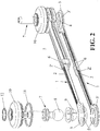
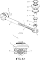
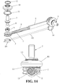
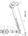
- the stabilizer for vehicle suspension proposed by the invention comprises a longitudinal body having two ends (3) and a central sector (2), having a hole (4) at each end (3) wherein there is housed a ball joint (7) or articulation element.
- the longitudinal body is formed by a metal frame embedded in polymer material.
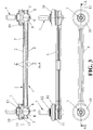
- the metal frame is in turn made up of two identical metal parts (1) which are arranged opposite one another and kept attached by means of an overmolded plastic body (5) preventing the separation of the parts (1).
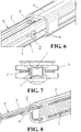
- Each part (1) also comprises at least one central hole (2'), though preferably it has two, located in the central sector (2), where the central sector (2) of the parts (1) is hollow, allowing the passage of the material of the overmolded body (5) to fill the inside of the central sectors (2) of the opposing parts (1).
- Each part (1) of the frame comprises two tabs (6) in the central sector (2) which are opposing when the two parts (1) are positioned, such that the two tabs (6) in each part (1) are located in opposition on each side and facing the open side, which allows contacting with the tabs (6) of the complementary part (1) that is arranged opposite to obtain the stabilizer, prior to injecting the overmolded body (5).
- the inner supports or rims (3') comprised in the ends (3) of the metal parts (1) are also in contact in said opposing position, being at the same level as the tabs (6), whereby achieving greater stability of the stabilizer and greater ease in obtaining it because clearances and movement of the metal parts (1) while injecting the overmolded body (5) are prevented.
- the stabilizer also comprises a seat (9) or a housing element in correspondence with each ball joint (7) having a spherical inner surface suitable for housing the spherical portion (8) of the ball joint (7).
- the central sector (2) of the parts (1) is slender and the holes (4) of the ends are circular, being concentric to the outer profile of the ends (3) which is also mostly circular.
- the axes of the two holes (4) of the ends (3) are also positioned perpendicular to the longitudinal axis (13) of the straight sector (2) of each part (1), which is symmetrical with respect to the longitudinal axis and is substantially planar.
- the stabilizer comprises at least one dust seal (10) or leak-tight element located at one end (3) suitable for protecting the spherical element (8) of the ball joint (7), with the corresponding rings (11,12) or elements for fixing it.
- each metal part (1) has a plurality of holes so that when the polymer is overmolded the attachment between the two metal parts (1) is more robust. Moment of inertia in that transverse area is lost due to the perforation of the metal part. To compensate for this phenomenon, it is contemplated that each metal part (1) has central tabs (6) in that area to prevent this loss, although the arrangement of tabs (6) in the central portion (2) of each of the metal parts (1) forming the frame is contemplated independently of the holes. The purpose of these tabs (6) is to weld both metal parts (1) in that central area (2) to facilitate the assembly and make the stabilizer more robust.
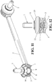
- the orientation of the axes of the holes (4) of the ends (3) of the stabilizer are oriented with respect to one another between 0° and 90°. Due to the rotation occurring in the metal frame, it is contemplated that the section of the stabilizer is circular, instead of the preferred section of the invention in which the geometry of the section is H- or I-shaped, which simplifies the injection process.
- the stabilizer comprises a plastic tube (15) introduced between both metal parts (1) is contemplated.
- the inclusion of the tube (15) improves the injection process in addition to saving injected material.
- the tube (15) must be closed at its ends.
- the stabilizer comprises two plastic rings (14) bracing the articulations (7), being externally located at the end (3) of each metal part (1).
- the introduction of the rings (14) facilitates the assembly of the two metal parts (1) with one another.
- the tube (15) and the two rings (14) are attached forming a sub-assembly.
Landscapes
- Engineering & Computer Science (AREA)
- Mechanical Engineering (AREA)
- Vehicle Body Suspensions (AREA)
- Pivots And Pivotal Connections (AREA)
Claims (13)
- Stabilisator für Fahrzeugaufhängung, umfassend:- einen polymeren Längskörper mit einem Metallrahmen, der zwei Enden (3) und einen mittleren Sektor (2) aufweist, mit einem Loch (4) an jedem Ende (3), wobei darin ein Kugelgelenk (7) aufgenommen ist,dadurch gekennzeichnet, dass der Rahmen aus zwei Metallteilen (1) mit einem offenen Querschnitt gebildet ist, die einander gegenüber liegend an ihren offenen Seiten angeordnet sind, wobei der mittlere Sektor (2) jedes Teils (1) zwei Streifen (6) aufweist, die entgegengesetzt auf jeder Seite angeordnet und der offenen Seite zugewandt sind, und die Enden (3) Ränder (3') aufweisen, so dass die zwei gegenüber liegenden Teile (1) auf den Streifen (6) und auf den Rändern (3') zur Anlage kommen und in einem überformten Körper (5) eingebettet sind, der sie von außen bedeckt und den durch die zwei gegenüber liegenden Metallteile (1) gebildeten Innenraum ausfüllt.
- Stabilisator nach Anspruch 1, wobei jeder Teil (1) mindestens eine in dem mittleren Sektor (2) angeordnete mittlere Öffnung (2') umfasst, die mit Kunststoff des überforderten Körpers (5) ausgefüllt werden kann, was das mechanische Verhalten der Baugruppe verbessert.
- Stabilisator nach einem der vorhergehenden Ansprüche, wobei der mittlere Sektor (2) der Teile (1) schlank ist und die Löcher (4) der Enden kreisförmig sind, die konzentrisch zum Außenprofil der Enden (3) sind, das auch meistens kreisförmig ist.
- Stabilisator nach Anspruch 3, wobei die Achsen der zwei Löcher (4) der Enden (3) senkrecht zur Längsachse (13) des geraden Sektors (2) jedes Teils (1) angeordnet sind.
- Stabilisator nach Anspruch 4, wobei jeder Teil (1) symmetrisch bezüglich der Längsachse ist.
- Stabilisator nach einem der vorhergehenden Ansprüche, wobei die Teile (1) im Wesentlichen eben sind und durch Pressformen erhalten werden können.
- Stabilisator nach einem der Ansprüche 1 bis 4 oder 6, wobei die Ausrichtung der Achsen der Löcher (4) der Enden (3) des Stabilisators im Verhältnis zueinander zwischen 0° und 90° ausgerichtet sind.
- Stabilisator nach Anspruch 7, wobei der Querschnitt des Stabilisators kreisförmig ist.
- Stabilisator nach einem der vorhergehenden Ansprüche, umfassend ein Kunststoffrohr (15), das zwischen beiden Metallteilen (1) eingeführt wird, wobei jedes Ende des Rohrs (15) an einem Kunststoffring (14) befestigt ist, der das Ende (3) jedes Metallteils (1) spannt.
- Stabilisator nach einem der vorhergehenden Ansprüche, der mindestens eine Klemme (16) enthält, die die Enden der Metallteile (1) verbindet.
- Aufhängungssystem, das eine Stabilisator nach einem der Ansprüche 1 bis 10 enthält.
- Fahrzeug, das einen Stabilisator nach einem der Ansprüche 1 bis 10 umfasst.
- Fahrzeug nach Anspruch 12, wobei der Stabilisator ein Kugelgelenk (7), das mit einem Rad des Fahrzeugs verbunden ist, und ein Kugelgelenk (7), das an einem Rahmen des Fahrzeugs gelenkig angebracht ist, aufweist.
Priority Applications (5)
| Application Number | Priority Date | Filing Date | Title |
|---|---|---|---|
| ES12382305(6)T ES2677820T3 (es) | 2012-07-27 | 2012-07-27 | Estabilizador para vehículos |
| EP12382305.6A EP2689943B1 (de) | 2012-07-27 | 2012-07-27 | Stabilisator für Fahrzeuge |
| MX2013008597A MX339221B (es) | 2012-07-27 | 2013-07-24 | Estabilizador para suspension de vehiculos. |
| CN201310394517.9A CN103707735B (zh) | 2012-07-27 | 2013-07-25 | 用于车辆悬架的稳定器 |
| US13/953,657 US8870202B2 (en) | 2012-07-27 | 2013-07-29 | Stabilizer for vehicle suspension |
Applications Claiming Priority (1)
| Application Number | Priority Date | Filing Date | Title |
|---|---|---|---|
| EP12382305.6A EP2689943B1 (de) | 2012-07-27 | 2012-07-27 | Stabilisator für Fahrzeuge |
Publications (2)
| Publication Number | Publication Date |
|---|---|
| EP2689943A1 EP2689943A1 (de) | 2014-01-29 |
| EP2689943B1 true EP2689943B1 (de) | 2018-06-06 |
Family
ID=46970175
Family Applications (1)
| Application Number | Title | Priority Date | Filing Date |
|---|---|---|---|
| EP12382305.6A Not-in-force EP2689943B1 (de) | 2012-07-27 | 2012-07-27 | Stabilisator für Fahrzeuge |
Country Status (5)
| Country | Link |
|---|---|
| US (1) | US8870202B2 (de) |
| EP (1) | EP2689943B1 (de) |
| CN (1) | CN103707735B (de) |
| ES (1) | ES2677820T3 (de) |
| MX (1) | MX339221B (de) |
Families Citing this family (18)
| Publication number | Priority date | Publication date | Assignee | Title |
|---|---|---|---|---|
| EP2759423B1 (de) * | 2013-01-28 | 2015-04-22 | Gestamp Umformtechnik GmbH | Querlenker aus faserverstärktem Kunststoff für eine Radaufhängung eines Fahrzeuges |
| DE102014214827A1 (de) * | 2014-07-29 | 2016-02-04 | Zf Friedrichshafen Ag | Lenker sowie Verfahren zu dessen Herstellung |
| US9381949B2 (en) * | 2014-10-15 | 2016-07-05 | Toyota Motor Engineering & Manufacturing North America, Inc. | Vehicles having a cross-vehicle stabilizing structure |
| US9260138B1 (en) | 2014-10-21 | 2016-02-16 | Toyota Motor Engineering & Manufacturing North America, Inc. | Vehicles having a cross-vehicle stabilizing structure |
| US20160280037A1 (en) * | 2015-03-23 | 2016-09-29 | Toyota Motor Engineering & Manufacturing North America, Inc. | Stabilizer link |
| CN105459749A (zh) * | 2015-12-11 | 2016-04-06 | 北汽福田汽车股份有限公司 | 车辆及其减振器 |
| JP6335986B2 (ja) * | 2016-08-25 | 2018-05-30 | 日本発條株式会社 | スタビリンク |
| CA171209S (en) * | 2016-10-24 | 2017-05-18 | Mevotech Lp | Stabilizer link |
| EP3330112A1 (de) * | 2016-12-02 | 2018-06-06 | Engineering Developments for Automotive Industry, S.L. | Stabilisator für eine fahrzeugaufhängung |
| DE102017204464A1 (de) * | 2017-03-17 | 2018-09-20 | Bayerische Motoren Werke Aktiengesellschaft | Fahrwerkskomponente für ein Kraftfahrzeug und Verfahren zum Herstellen einer Fahrwerkskomponente |
| JP6832206B2 (ja) * | 2017-03-29 | 2021-02-24 | 日本発條株式会社 | ボールジョイント、及びこれを用いたスタビリンク |
| DE102017207164A1 (de) * | 2017-04-28 | 2018-10-31 | Zf Friedrichshafen Ag | Achsstrebe und Verfahren zur Herstellung einer Achsstrebe |
| CN109955667A (zh) * | 2017-12-26 | 2019-07-02 | 汽车工业工程发展公司 | 用于车辆悬架的稳定器 |
| DE102018219102B4 (de) * | 2018-11-08 | 2025-04-30 | Audi Ag | Stabilisator für ein Kraftfahrzeug |
| CN110667736B (zh) * | 2019-10-11 | 2020-07-21 | 湖北工业大学 | 一种复杂地形自适应弹簧平衡结构 |
| USD1029882S1 (en) * | 2020-01-23 | 2024-06-04 | SpeedyRacing, LLC | Motor vehicle suspension stabilizer link |
| RU203168U1 (ru) * | 2020-12-18 | 2021-03-24 | Общество с ограниченной ответственностью «Белебеевский завод «Автокомплект» | Стойка стабилизатора поперечной устойчивости автомобиля |
| CN116181783A (zh) * | 2023-01-18 | 2023-05-30 | 博戈橡胶塑料(株洲)有限公司 | 一种提高轻量化推力杆抗扭和抗偏转性能的方法及推力杆 |
Family Cites Families (13)
| Publication number | Priority date | Publication date | Assignee | Title |
|---|---|---|---|---|
| US1817529A (en) * | 1930-09-02 | 1931-08-04 | O & S Bearing Company | Method of forming a permanent connecting link |
| DE3619003A1 (de) * | 1986-06-05 | 1987-12-10 | Trw Ehrenreich Gmbh | Kugelgelenk |
| US5165306A (en) * | 1990-10-04 | 1992-11-24 | Maclean-Fogg Company | Vehicle stabilizer bar end link |
| DE4441219C2 (de) * | 1994-11-19 | 2001-12-06 | Zf Lemfoerder Metallwaren Ag | Pendelstütze für das Einsetzen von die Lagerstellen bildenden Lagerhüben für die gelenkige Verbindung von Fahrwerksteilen in Kraftfahrzeugen |
| US5885688A (en) * | 1996-12-26 | 1999-03-23 | The Pullman Company | Steel reinforced filled polymer torque rod |
| FR2835024B1 (fr) * | 2002-01-18 | 2004-07-02 | Cf Gomma Spa | Bras, ou bielle, de liaison et son procede de fabrication |
| DE10341629B4 (de) * | 2003-09-10 | 2007-04-12 | Groz-Beckert Kg | Vibrationsarmes Fachbildesystem |
| US20070069496A1 (en) * | 2005-09-27 | 2007-03-29 | Rinehart Ronald A | Torsion beam suspension member |
| DE102006002749A1 (de) * | 2006-01-20 | 2007-09-20 | Dr.Ing.H.C. F. Porsche Ag | Lagerelement |
| CN101279402A (zh) * | 2007-04-04 | 2008-10-08 | 山下橡胶株式会社 | 连杆的制法 |
| DE102008002524A1 (de) * | 2008-06-19 | 2009-12-24 | Zf Friedrichshafen Ag | Stabilisator für ein Nutzfahrzeug |
| DE102009031846A1 (de) * | 2009-07-03 | 2011-01-05 | GM Global Technology Operations, Inc., Detroit | Hinterachse vom Verbundlenkerachstyp für Kraftfahrzeug |
| KR101180942B1 (ko) * | 2009-12-04 | 2012-09-07 | 현대자동차주식회사 | 서스펜션 암 |
-
2012
- 2012-07-27 EP EP12382305.6A patent/EP2689943B1/de not_active Not-in-force
- 2012-07-27 ES ES12382305(6)T patent/ES2677820T3/es active Active
-
2013
- 2013-07-24 MX MX2013008597A patent/MX339221B/es active IP Right Grant
- 2013-07-25 CN CN201310394517.9A patent/CN103707735B/zh not_active Expired - Fee Related
- 2013-07-29 US US13/953,657 patent/US8870202B2/en active Active
Non-Patent Citations (1)
| Title |
|---|
| None * |
Also Published As
| Publication number | Publication date |
|---|---|
| MX2013008597A (es) | 2014-01-27 |
| CN103707735B (zh) | 2017-04-12 |
| CN103707735A (zh) | 2014-04-09 |
| US8870202B2 (en) | 2014-10-28 |
| ES2677820T3 (es) | 2018-08-07 |
| EP2689943A1 (de) | 2014-01-29 |
| US20140035249A1 (en) | 2014-02-06 |
| MX339221B (es) | 2016-05-17 |
Similar Documents
| Publication | Publication Date | Title |
|---|---|---|
| EP2689943A1 (de) | Stabilisator für Fahrzeuge | |
| EP3398796B1 (de) | Hybrid-fahrwerkslenker | |
| JP5923154B2 (ja) | リンクアーム部材 | |
| CN108688430B (zh) | 用于汽车悬架的稳定连杆 | |
| US20090033142A1 (en) | Powered motor vehicle rear axle of a twist-beam axle type | |
| KR101972245B1 (ko) | 완충기 | |
| RU2465151C2 (ru) | Рычаг подвески транспортного средства | |
| KR20100134086A (ko) | 비틀림 슬립을 갖는 굴곡된 부싱 | |
| CN204955998U (zh) | 车辆扭梁结构 | |
| KR20130120452A (ko) | 하이브리드 크로스 액시스 볼 조인트 부싱 | |
| US20030141757A1 (en) | Flexible axle for motor vehicle with improved antiroll device | |
| US20020171221A1 (en) | Robust, low mass stabilizer bar link assembly | |
| JP2009511348A (ja) | スタビライザバー | |
| US9150079B2 (en) | Coupled torsion beam axle type suspension system | |
| US20180154732A1 (en) | Stabilizer for a vehicle suspension | |
| US9302706B2 (en) | Articulated connection for transferring a steering movement onto a vehicle wheel | |
| KR200487124Y1 (ko) | 차량용 스테빌라이저 | |
| US12188515B2 (en) | Ball joint, suspension arm comprising same, and manufacturing method thereof | |
| KR20110062009A (ko) | 차량용 부시장착구조 | |
| JP4701947B2 (ja) | 操舵輪用ストラット式サスペンション | |
| KR102406141B1 (ko) | 커플드 토션 빔 액슬 타입 현가장치의 차체 마운팅 구조 | |
| EP3421275A1 (de) | Stabilisatorverbindung für eine fahrzeugaufhängung |
Legal Events
| Date | Code | Title | Description |
|---|---|---|---|
| PUAI | Public reference made under article 153(3) epc to a published international application that has entered the european phase |
Free format text: ORIGINAL CODE: 0009012 |
|
| AK | Designated contracting states |
Kind code of ref document: A1 Designated state(s): AL AT BE BG CH CY CZ DE DK EE ES FI FR GB GR HR HU IE IS IT LI LT LU LV MC MK MT NL NO PL PT RO RS SE SI SK SM TR |
|
| AX | Request for extension of the european patent |
Extension state: BA ME |
|
| 17P | Request for examination filed |
Effective date: 20140331 |
|
| RBV | Designated contracting states (corrected) |
Designated state(s): AL AT BE BG CH CY CZ DE DK EE ES FI FR GB GR HR HU IE IS IT LI LT LU LV MC MK MT NL NO PL PT RO RS SE SI SK SM TR |
|
| 17Q | First examination report despatched |
Effective date: 20160714 |
|
| STAA | Information on the status of an ep patent application or granted ep patent |
Free format text: STATUS: EXAMINATION IS IN PROGRESS |
|
| GRAP | Despatch of communication of intention to grant a patent |
Free format text: ORIGINAL CODE: EPIDOSNIGR1 |
|
| STAA | Information on the status of an ep patent application or granted ep patent |
Free format text: STATUS: GRANT OF PATENT IS INTENDED |
|
| RAP1 | Party data changed (applicant data changed or rights of an application transferred) |
Owner name: ENGINEERING DEVELOPMENTS FOR AUTOMOTIVE INDUSTRY, |
|
| INTG | Intention to grant announced |
Effective date: 20180326 |
|
| GRAS | Grant fee paid |
Free format text: ORIGINAL CODE: EPIDOSNIGR3 |
|
| GRAA | (expected) grant |
Free format text: ORIGINAL CODE: 0009210 |
|
| STAA | Information on the status of an ep patent application or granted ep patent |
Free format text: STATUS: THE PATENT HAS BEEN GRANTED |
|
| AK | Designated contracting states |
Kind code of ref document: B1 Designated state(s): AL AT BE BG CH CY CZ DE DK EE ES FI FR GB GR HR HU IE IS IT LI LT LU LV MC MK MT NL NO PL PT RO RS SE SI SK SM TR |
|
| REG | Reference to a national code |
Ref country code: GB Ref legal event code: FG4D |
|
| REG | Reference to a national code |
Ref country code: CH Ref legal event code: EP Ref country code: AT Ref legal event code: REF Ref document number: 1005677 Country of ref document: AT Kind code of ref document: T Effective date: 20180615 |
|
| REG | Reference to a national code |
Ref country code: IE Ref legal event code: FG4D |
|
| REG | Reference to a national code |
Ref country code: DE Ref legal event code: R096 Ref document number: 602012047133 Country of ref document: DE |
|
| REG | Reference to a national code |
Ref country code: FR Ref legal event code: PLFP Year of fee payment: 7 |
|
| REG | Reference to a national code |
Ref country code: ES Ref legal event code: FG2A Ref document number: 2677820 Country of ref document: ES Kind code of ref document: T3 Effective date: 20180807 |
|
| REG | Reference to a national code |
Ref country code: NL Ref legal event code: MP Effective date: 20180606 |
|
| REG | Reference to a national code |
Ref country code: LT Ref legal event code: MG4D |
|
| PG25 | Lapsed in a contracting state [announced via postgrant information from national office to epo] |
Ref country code: NO Free format text: LAPSE BECAUSE OF FAILURE TO SUBMIT A TRANSLATION OF THE DESCRIPTION OR TO PAY THE FEE WITHIN THE PRESCRIBED TIME-LIMIT Effective date: 20180906 Ref country code: FI Free format text: LAPSE BECAUSE OF FAILURE TO SUBMIT A TRANSLATION OF THE DESCRIPTION OR TO PAY THE FEE WITHIN THE PRESCRIBED TIME-LIMIT Effective date: 20180606 Ref country code: CY Free format text: LAPSE BECAUSE OF FAILURE TO SUBMIT A TRANSLATION OF THE DESCRIPTION OR TO PAY THE FEE WITHIN THE PRESCRIBED TIME-LIMIT Effective date: 20180606 Ref country code: LT Free format text: LAPSE BECAUSE OF FAILURE TO SUBMIT A TRANSLATION OF THE DESCRIPTION OR TO PAY THE FEE WITHIN THE PRESCRIBED TIME-LIMIT Effective date: 20180606 Ref country code: SE Free format text: LAPSE BECAUSE OF FAILURE TO SUBMIT A TRANSLATION OF THE DESCRIPTION OR TO PAY THE FEE WITHIN THE PRESCRIBED TIME-LIMIT Effective date: 20180606 Ref country code: BG Free format text: LAPSE BECAUSE OF FAILURE TO SUBMIT A TRANSLATION OF THE DESCRIPTION OR TO PAY THE FEE WITHIN THE PRESCRIBED TIME-LIMIT Effective date: 20180906 |
|
| PG25 | Lapsed in a contracting state [announced via postgrant information from national office to epo] |
Ref country code: LV Free format text: LAPSE BECAUSE OF FAILURE TO SUBMIT A TRANSLATION OF THE DESCRIPTION OR TO PAY THE FEE WITHIN THE PRESCRIBED TIME-LIMIT Effective date: 20180606 Ref country code: RS Free format text: LAPSE BECAUSE OF FAILURE TO SUBMIT A TRANSLATION OF THE DESCRIPTION OR TO PAY THE FEE WITHIN THE PRESCRIBED TIME-LIMIT Effective date: 20180606 Ref country code: GR Free format text: LAPSE BECAUSE OF FAILURE TO SUBMIT A TRANSLATION OF THE DESCRIPTION OR TO PAY THE FEE WITHIN THE PRESCRIBED TIME-LIMIT Effective date: 20180907 Ref country code: HR Free format text: LAPSE BECAUSE OF FAILURE TO SUBMIT A TRANSLATION OF THE DESCRIPTION OR TO PAY THE FEE WITHIN THE PRESCRIBED TIME-LIMIT Effective date: 20180606 |
|
| REG | Reference to a national code |
Ref country code: AT Ref legal event code: MK05 Ref document number: 1005677 Country of ref document: AT Kind code of ref document: T Effective date: 20180606 |
|
| PG25 | Lapsed in a contracting state [announced via postgrant information from national office to epo] |
Ref country code: NL Free format text: LAPSE BECAUSE OF FAILURE TO SUBMIT A TRANSLATION OF THE DESCRIPTION OR TO PAY THE FEE WITHIN THE PRESCRIBED TIME-LIMIT Effective date: 20180606 |
|
| PG25 | Lapsed in a contracting state [announced via postgrant information from national office to epo] |
Ref country code: IS Free format text: LAPSE BECAUSE OF FAILURE TO SUBMIT A TRANSLATION OF THE DESCRIPTION OR TO PAY THE FEE WITHIN THE PRESCRIBED TIME-LIMIT Effective date: 20181006 Ref country code: AT Free format text: LAPSE BECAUSE OF FAILURE TO SUBMIT A TRANSLATION OF THE DESCRIPTION OR TO PAY THE FEE WITHIN THE PRESCRIBED TIME-LIMIT Effective date: 20180606 Ref country code: EE Free format text: LAPSE BECAUSE OF FAILURE TO SUBMIT A TRANSLATION OF THE DESCRIPTION OR TO PAY THE FEE WITHIN THE PRESCRIBED TIME-LIMIT Effective date: 20180606 Ref country code: PL Free format text: LAPSE BECAUSE OF FAILURE TO SUBMIT A TRANSLATION OF THE DESCRIPTION OR TO PAY THE FEE WITHIN THE PRESCRIBED TIME-LIMIT Effective date: 20180606 Ref country code: SK Free format text: LAPSE BECAUSE OF FAILURE TO SUBMIT A TRANSLATION OF THE DESCRIPTION OR TO PAY THE FEE WITHIN THE PRESCRIBED TIME-LIMIT Effective date: 20180606 Ref country code: CZ Free format text: LAPSE BECAUSE OF FAILURE TO SUBMIT A TRANSLATION OF THE DESCRIPTION OR TO PAY THE FEE WITHIN THE PRESCRIBED TIME-LIMIT Effective date: 20180606 Ref country code: RO Free format text: LAPSE BECAUSE OF FAILURE TO SUBMIT A TRANSLATION OF THE DESCRIPTION OR TO PAY THE FEE WITHIN THE PRESCRIBED TIME-LIMIT Effective date: 20180606 |
|
| PG25 | Lapsed in a contracting state [announced via postgrant information from national office to epo] |
Ref country code: SM Free format text: LAPSE BECAUSE OF FAILURE TO SUBMIT A TRANSLATION OF THE DESCRIPTION OR TO PAY THE FEE WITHIN THE PRESCRIBED TIME-LIMIT Effective date: 20180606 |
|
| REG | Reference to a national code |
Ref country code: CH Ref legal event code: PL |
|
| REG | Reference to a national code |
Ref country code: DE Ref legal event code: R097 Ref document number: 602012047133 Country of ref document: DE |
|
| PG25 | Lapsed in a contracting state [announced via postgrant information from national office to epo] |
Ref country code: LU Free format text: LAPSE BECAUSE OF NON-PAYMENT OF DUE FEES Effective date: 20180727 Ref country code: MC Free format text: LAPSE BECAUSE OF FAILURE TO SUBMIT A TRANSLATION OF THE DESCRIPTION OR TO PAY THE FEE WITHIN THE PRESCRIBED TIME-LIMIT Effective date: 20180606 |
|
| PLBE | No opposition filed within time limit |
Free format text: ORIGINAL CODE: 0009261 |
|
| STAA | Information on the status of an ep patent application or granted ep patent |
Free format text: STATUS: NO OPPOSITION FILED WITHIN TIME LIMIT |
|
| PG25 | Lapsed in a contracting state [announced via postgrant information from national office to epo] |
Ref country code: LI Free format text: LAPSE BECAUSE OF NON-PAYMENT OF DUE FEES Effective date: 20180731 Ref country code: CH Free format text: LAPSE BECAUSE OF NON-PAYMENT OF DUE FEES Effective date: 20180731 |
|
| REG | Reference to a national code |
Ref country code: IE Ref legal event code: MM4A |
|
| 26N | No opposition filed |
Effective date: 20190307 |
|
| PG25 | Lapsed in a contracting state [announced via postgrant information from national office to epo] |
Ref country code: SI Free format text: LAPSE BECAUSE OF FAILURE TO SUBMIT A TRANSLATION OF THE DESCRIPTION OR TO PAY THE FEE WITHIN THE PRESCRIBED TIME-LIMIT Effective date: 20180606 Ref country code: DK Free format text: LAPSE BECAUSE OF FAILURE TO SUBMIT A TRANSLATION OF THE DESCRIPTION OR TO PAY THE FEE WITHIN THE PRESCRIBED TIME-LIMIT Effective date: 20180606 |
|
| PG25 | Lapsed in a contracting state [announced via postgrant information from national office to epo] |
Ref country code: IE Free format text: LAPSE BECAUSE OF NON-PAYMENT OF DUE FEES Effective date: 20180727 |
|
| PG25 | Lapsed in a contracting state [announced via postgrant information from national office to epo] |
Ref country code: AL Free format text: LAPSE BECAUSE OF FAILURE TO SUBMIT A TRANSLATION OF THE DESCRIPTION OR TO PAY THE FEE WITHIN THE PRESCRIBED TIME-LIMIT Effective date: 20180606 |
|
| PG25 | Lapsed in a contracting state [announced via postgrant information from national office to epo] |
Ref country code: MT Free format text: LAPSE BECAUSE OF NON-PAYMENT OF DUE FEES Effective date: 20180727 |
|
| PG25 | Lapsed in a contracting state [announced via postgrant information from national office to epo] |
Ref country code: TR Free format text: LAPSE BECAUSE OF FAILURE TO SUBMIT A TRANSLATION OF THE DESCRIPTION OR TO PAY THE FEE WITHIN THE PRESCRIBED TIME-LIMIT Effective date: 20180606 |
|
| PG25 | Lapsed in a contracting state [announced via postgrant information from national office to epo] |
Ref country code: PT Free format text: LAPSE BECAUSE OF FAILURE TO SUBMIT A TRANSLATION OF THE DESCRIPTION OR TO PAY THE FEE WITHIN THE PRESCRIBED TIME-LIMIT Effective date: 20180606 Ref country code: HU Free format text: LAPSE BECAUSE OF FAILURE TO SUBMIT A TRANSLATION OF THE DESCRIPTION OR TO PAY THE FEE WITHIN THE PRESCRIBED TIME-LIMIT; INVALID AB INITIO Effective date: 20120727 |
|
| PG25 | Lapsed in a contracting state [announced via postgrant information from national office to epo] |
Ref country code: MK Free format text: LAPSE BECAUSE OF NON-PAYMENT OF DUE FEES Effective date: 20180606 |
|
| PGFP | Annual fee paid to national office [announced via postgrant information from national office to epo] |
Ref country code: IT Payment date: 20220707 Year of fee payment: 11 Ref country code: ES Payment date: 20220804 Year of fee payment: 11 |
|
| PGFP | Annual fee paid to national office [announced via postgrant information from national office to epo] |
Ref country code: FR Payment date: 20220728 Year of fee payment: 11 Ref country code: BE Payment date: 20220722 Year of fee payment: 11 |
|
| PGFP | Annual fee paid to national office [announced via postgrant information from national office to epo] |
Ref country code: GB Payment date: 20230721 Year of fee payment: 12 |
|
| PGFP | Annual fee paid to national office [announced via postgrant information from national office to epo] |
Ref country code: DE Payment date: 20230728 Year of fee payment: 12 |
|
| REG | Reference to a national code |
Ref country code: BE Ref legal event code: MM Effective date: 20230731 |
|
| PG25 | Lapsed in a contracting state [announced via postgrant information from national office to epo] |
Ref country code: FR Free format text: LAPSE BECAUSE OF NON-PAYMENT OF DUE FEES Effective date: 20230731 Ref country code: BE Free format text: LAPSE BECAUSE OF NON-PAYMENT OF DUE FEES Effective date: 20230731 |
|
| PG25 | Lapsed in a contracting state [announced via postgrant information from national office to epo] |
Ref country code: IT Free format text: LAPSE BECAUSE OF NON-PAYMENT OF DUE FEES Effective date: 20230727 |
|
| REG | Reference to a national code |
Ref country code: ES Ref legal event code: FD2A Effective date: 20240830 |
|
| PG25 | Lapsed in a contracting state [announced via postgrant information from national office to epo] |
Ref country code: ES Free format text: LAPSE BECAUSE OF NON-PAYMENT OF DUE FEES Effective date: 20230728 |
|
| PG25 | Lapsed in a contracting state [announced via postgrant information from national office to epo] |
Ref country code: ES Free format text: LAPSE BECAUSE OF NON-PAYMENT OF DUE FEES Effective date: 20230728 |
|
| REG | Reference to a national code |
Ref country code: DE Ref legal event code: R119 Ref document number: 602012047133 Country of ref document: DE |
|
| GBPC | Gb: european patent ceased through non-payment of renewal fee |
Effective date: 20240727 |
|
| PG25 | Lapsed in a contracting state [announced via postgrant information from national office to epo] |
Ref country code: DE Free format text: LAPSE BECAUSE OF NON-PAYMENT OF DUE FEES Effective date: 20250201 |
|
| PG25 | Lapsed in a contracting state [announced via postgrant information from national office to epo] |
Ref country code: GB Free format text: LAPSE BECAUSE OF NON-PAYMENT OF DUE FEES Effective date: 20240727 |