EP2689970A1 - Circuit pour commander un consommatuer inductif avec circuit de roue libre - Google Patents
Circuit pour commander un consommatuer inductif avec circuit de roue libre Download PDFInfo
- Publication number
- EP2689970A1 EP2689970A1 EP13173677.9A EP13173677A EP2689970A1 EP 2689970 A1 EP2689970 A1 EP 2689970A1 EP 13173677 A EP13173677 A EP 13173677A EP 2689970 A1 EP2689970 A1 EP 2689970A1
- Authority
- EP
- European Patent Office
- Prior art keywords
- switch
- load
- circuit arrangement
- diode
- capacitor
- Prior art date
- Legal status (The legal status is an assumption and is not a legal conclusion. Google has not performed a legal analysis and makes no representation as to the accuracy of the status listed.)
- Withdrawn
Links
Images

Classifications
-
- H—ELECTRICITY
- H02—GENERATION; CONVERSION OR DISTRIBUTION OF ELECTRIC POWER
- H02H—EMERGENCY PROTECTIVE CIRCUIT ARRANGEMENTS
- H02H9/00—Emergency protective circuit arrangements for limiting excess current or voltage without disconnection
- H02H9/04—Emergency protective circuit arrangements for limiting excess current or voltage without disconnection responsive to excess voltage
- H02H9/045—Emergency protective circuit arrangements for limiting excess current or voltage without disconnection responsive to excess voltage adapted to a particular application and not provided for elsewhere
- H02H9/047—Free-wheeling circuits
-
- H—ELECTRICITY
- H01—ELECTRIC ELEMENTS
- H01F—MAGNETS; INDUCTANCES; TRANSFORMERS; SELECTION OF MATERIALS FOR THEIR MAGNETIC PROPERTIES
- H01F7/00—Magnets
- H01F7/06—Electromagnets; Actuators including electromagnets
- H01F7/08—Electromagnets; Actuators including electromagnets with armatures
- H01F7/18—Circuit arrangements for obtaining desired operating characteristics, e.g. for slow operation, for sequential energisation of windings, for high-speed energisation of windings
- H01F7/1805—Circuit arrangements for holding the operation of electromagnets or for holding the armature in attracted position with reduced energising current
- H01F7/1811—Circuit arrangements for holding the operation of electromagnets or for holding the armature in attracted position with reduced energising current demagnetising upon switching off, removing residual magnetism
Definitions
- the invention relates to a circuit arrangement, in particular for the operation of one or more inductive consumers.
- the DE 10 2011 011 295 A1 discloses a circuit for operating one or more inductive loads, in which the control of a second controllable switching element via an operating voltage, wherein a Zener diode is connected in series between the operating voltage and a control input of the second switching element.
- the local term "LOAD" is to be understood as an electrical load or electrical load. This may be, for example, the exciter coil of a starter motor, a solenoid valve for activating a differential lock or an automatic transmission.
- the symbols in the drawings are common symbols of electrical engineering.
- freewheeling diodes are often used to reduce the energy stored in the inductance after switching off and thus to achieve a so-called demagnetization.
- a freewheeling diode serves to protect a mechanical or electronic switch from an overvoltage that is generated when switching off a switched from him inductive DC load.
- a semiconductor diode is connected in parallel with the inductive DC load to be switched so that it is stressed by a supply voltage in the reverse direction. After the supply voltage has been switched off, the self-induction, for example of the coil, ensures that the current initially continues to flow in the original direction. Without the arrangement of the freewheeling diode switching off the supply voltage leads to a voltage spike, which adds to the operating voltage and can damage or destroy the switching path.
- the voltage spike is limited to the forward voltage of the semiconductor diode, which is about 0.7 V in a silicon diode, thereby providing effective overvoltage protection.
- the current flows through the semiconductor diode and the energy of the magnetic field is largely in the ohmic resistance of the coil and converted to a small part in the semiconductor diode into heat.
- Free-wheeling diodes are particularly important when the inductive load is operated in a pulse-width-modulated manner (PWM operation).
- PWM operation a freewheeling average current proportional to the duty cycle of on / off time can be set in the load.
- Typical inductive loads are for example solenoid valves, which are used in motor vehicles, especially in commercial vehicles.
- the inductive load is bipolar connected to the control unit (ECU), such as the motor vehicle, in addition to the electromagnetic advantages in PWM operation, in the case of a break in the power supply in the ground branch no parasitic current can flow to the load.
- ECU control unit
- the invention has the object to improve a circuit arrangement such that An unwanted activation, in particular an inductive load is reliably avoided even with technical defects.
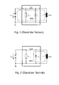
- Fig. 1 is the regular current flow I L shown with two-pole load connection. If the load is connected to a control unit with two poles, the reverse current I L flows back through the control unit. The dashed line illustrates the current flow.
- FIG. 2 To Fig. 2 is the current flow I L in the freewheel with a two-pole load connection represented by the dashed line.
- the energy stored in the inductive load is dissipated via a freewheeling path, demagnetized.
- the current loop that forms is correspondingly small.
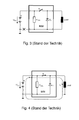
- Fig. 3 is a Masseabriss in two-pole load connection through the large cross shown lower left. This means that, for example, due to a technical defect, a ground cable no longer forms any contact between the circuit arrangement and the negative pole of the battery in the motor vehicle. In the case of a two-pole load connection, the current flow is interrupted in the event of a ground fault.
- Fig. 4 is the regular current flow I L at one-pole load connection represented by the dashed line. If the load is connected to the control unit with a single pole, the reverse current flows via the system ground to the negative terminal of the battery.
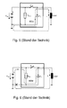
- Fig. 5 To Fig. 5 is the current flow I L freewheeling in unipolar load connection represented by the dashed line.
- the switch S 1 When opening the switch S 1 , the energy stored in the inductive load via the freewheeling path is reduced (demagnetized). In the case of a single-pole load connection, the current loop that forms is correspondingly large.
- Fig. 6 is the current flow I L during mass split at one-pole load connection represented by the dashed line.
- this certain parasitic current flows via the control unit (ECU) and the freewheeling diode D 1 to the load and system ground.
- the forming current is dependent on the internal resistance R ECU of the control unit and can activate the connected load unintentionally.
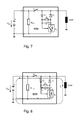
- the Fig. 7 shows a circuit arrangement according to the invention with dynamic freewheeling.
- a load connected to the control unit can be activated unintentionally via its freewheel device, such as a single diode.
- the circuit arrangement shown here prevents this.
- a forward-biased diode is connected in series with a capacitor C 1 , which has a resistance R 1 connected in parallel.
- a further switch S 2 is provided in addition to the switch S 1 , which is bridged with a diode which is likewise connected in the forward direction.
- Fig. 8 is the regular current flow I L at one-pole load connection with dynamic freewheel represented by the dashed line.
- the capacitor C 1 When activating the load, the capacitor C 1 is simultaneously charged by a further current flow I C , as the dotted line illustrates.
- FIG. 9 the current flow I L in the dynamic freewheel with a one-pole load connection is shown by the dashed line.
- the freewheel is only activated until the capacitor C 1 is discharged through the resistor R 1 , as the dotted line shows.
- the dimensioning of C 1 and R 1 is chosen so that the corresponding time constant, which is formed from C 1 * R 1 , is greater than the time constant representing the inductive load with L L / R L.
- Fig. 10 the operating situation during mass break is shown with a one-pole load connection with dynamic freewheel. After the capacitor C 1 is discharged, the switch S 2 opens and the current flow is interrupted. In the case of a Masseabrisses no unwanted current can flow to the load.
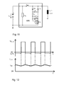
- FIG. 11 is a possible circuit design shown with dynamic freewheel.
- a switch S 2 a conventional N-channel MOS-Fet transistor can be used.
- a zener diode ZD 1 is used to limit the gate voltage, which typically may not exceed 20V.
- the freewheeling diode D 1 and the switch S 2 must be selected so that they can carry the impressed current into the connected load during the freewheeling (Demagnetleitersphase).
- the time constant t charge for charging the capacitor C 1 must be less than the minimum duty cycle of the switch S 1 . This is also called a "minimum duty cycle”.
- the time constant t discharge must be greater than the time constant given by the inductive load, ie: (R 1 + R 2 ) * C 1 > L L / R L.
- the so-called PWM operation the inductive load, flows in it a triangular current I load whose mean value l avg is proportional to the pulse width.
- I load whose mean value l avg is proportional to the pulse width.
- the freewheeling branch is to be designed in such a way that, on the one hand, the inductive load connected in a single pole can be operated with PWM, and on the other hand, if there is a possible disconnection of the ground line of the control unit, no unwanted current flows to the load.
- Such a circuit arrangement is preferably used in a motor vehicle for controlling inductive loads, in particular for controlling solenoid valves of a differential lock or an automatic transmission.
Landscapes
- Physics & Mathematics (AREA)
- Electromagnetism (AREA)
- Engineering & Computer Science (AREA)
- Power Engineering (AREA)
- Electronic Switches (AREA)
Applications Claiming Priority (2)
| Application Number | Priority Date | Filing Date | Title |
|---|---|---|---|
| DE102012013362 | 2012-07-08 | ||
| DE102012109011.4A DE102012109011A1 (de) | 2012-07-08 | 2012-09-25 | Schaltungsanordnung |
Publications (1)
| Publication Number | Publication Date |
|---|---|
| EP2689970A1 true EP2689970A1 (fr) | 2014-01-29 |
Family
ID=48746283
Family Applications (1)
| Application Number | Title | Priority Date | Filing Date |
|---|---|---|---|
| EP13173677.9A Withdrawn EP2689970A1 (fr) | 2012-07-08 | 2013-06-25 | Circuit pour commander un consommatuer inductif avec circuit de roue libre |
Country Status (2)
| Country | Link |
|---|---|
| EP (1) | EP2689970A1 (fr) |
| DE (1) | DE102012109011A1 (fr) |
Families Citing this family (2)
| Publication number | Priority date | Publication date | Assignee | Title |
|---|---|---|---|---|
| US8917135B2 (en) * | 2013-05-14 | 2014-12-23 | Infineon Technologies Austria Ag | Circuit with a plurality of diodes and method for controlling such a circuit |
| DE102018203887B4 (de) * | 2018-03-14 | 2022-05-25 | Bayerische Motoren Werke Aktiengesellschaft | Steuergerät für ein Mehrspannungsbordnetz eines Fahrzeugs und Mehrspannungsbordnetz |
Citations (3)
| Publication number | Priority date | Publication date | Assignee | Title |
|---|---|---|---|---|
| DE19806311A1 (de) * | 1998-02-16 | 1999-08-26 | Siemens Ag | Vorrichtung zum Schalten induktiver Verbraucher |
| WO2005055387A1 (fr) * | 2003-12-01 | 2005-06-16 | Siemens Aktiengesellschaft | Ensemble circuit et procede de commande d'un consommateur inductif |
| DE102011011295A1 (de) | 2011-02-15 | 2012-08-16 | Hella Kgaa Hueck & Co. | Stromversorgungsanordnung für ohmsch-induktiven Verbraucher |
-
2012
- 2012-09-25 DE DE102012109011.4A patent/DE102012109011A1/de not_active Ceased
-
2013
- 2013-06-25 EP EP13173677.9A patent/EP2689970A1/fr not_active Withdrawn
Patent Citations (4)
| Publication number | Priority date | Publication date | Assignee | Title |
|---|---|---|---|---|
| DE19806311A1 (de) * | 1998-02-16 | 1999-08-26 | Siemens Ag | Vorrichtung zum Schalten induktiver Verbraucher |
| WO2005055387A1 (fr) * | 2003-12-01 | 2005-06-16 | Siemens Aktiengesellschaft | Ensemble circuit et procede de commande d'un consommateur inductif |
| DE10356089B4 (de) | 2003-12-01 | 2005-11-03 | Siemens Ag | Schaltungsanordnung und Verfahren zum Steuern eines induktiven Verbrauchers |
| DE102011011295A1 (de) | 2011-02-15 | 2012-08-16 | Hella Kgaa Hueck & Co. | Stromversorgungsanordnung für ohmsch-induktiven Verbraucher |
Also Published As
| Publication number | Publication date |
|---|---|
| DE102012109011A1 (de) | 2014-01-09 |
Similar Documents
| Publication | Publication Date | Title |
|---|---|---|
| DE102016102417B4 (de) | Schutzschaltung für ein Photovoltaik (PV)-Modul, Verfahren zum Betrieb der Schutzschaltung und Photovoltaik (PV)-Anlage mit einer derartigen Schutzschaltung | |
| DE102016216331B3 (de) | Trennvorrichtung zur Stromunterbrechung, Schutzschalter mit einem Sensor und einer Trennvorrichtung sowie Verfahren zum Betrieb einer Trennvorrichtung | |
| DE102013208968B4 (de) | Kraftfahrzeugbordnetz mit aktivem Brückengleichrichter und Überspannungsschutz bei Lastabwurf, Gleichrichteranordnung, zugehöriges Betriebsverfahren und Mittel zu dessen Implementierung | |
| EP2711248B1 (fr) | Réseau de bord bitension avec protection contre les surtensions | |
| DE102013016960A1 (de) | Abschalten einer Wechselrichtereinheit und Betriebsverfahren | |
| WO2013127550A1 (fr) | Dispositif et procédé de protection d'un circuit électrique de véhicule et circuit électrique correspondant | |
| EP3221943B1 (fr) | Circuit de protection contre les surtensions et/ou les surintensités | |
| DE4134495A1 (de) | Steuereinrichtung fuer elektrische motoren in fahrzeugen | |
| DE102019204155B3 (de) | Fahrzeugelektroniksteuereinrichtung | |
| DE102018213130A1 (de) | Elektrisches Bordnetz und Kraftfahrzeug mit einem solchen Bordnetz | |
| WO2023011768A1 (fr) | Unité de disjoncteur | |
| DE102014200503A1 (de) | Verfahren zum Betreiben eines aktiven Gleichrichters, Schaltungsanordnung und Computerprogramm | |
| DE102007041784B4 (de) | Schaltungsanordnung zum Schalten einer induktiven Last | |
| DE102019210926A1 (de) | Verfahren und Steuergerät zum Kurzschließen von zumindest zwei Phasen einer elektrischen Maschine eines Fahrzeugs | |
| EP2689970A1 (fr) | Circuit pour commander un consommatuer inductif avec circuit de roue libre | |
| DE102014016239A1 (de) | Gleichspannungswandler für ein Kraftfahrzeug und Verfahren zum Betreiben eines derartigen Gleichspannungswandlers | |
| DE102012216185A1 (de) | Begrenzerschaltung für einen Halbleitertransistor und Verfahren zum Begrenzen der Spannung über einen Halbleitertransistor | |
| DE102012209774B4 (de) | Steuergerät zur Versorgung einer Last in einem Kraftfahrzeug mit einer Spannung und Schaltungsanordnung mit einem solchen Steuergerät | |
| WO2016074833A1 (fr) | Dispositif filtrant à commande active | |
| DE102013222841A1 (de) | Stromregler für eine induktive Last in einem Fahrzeug | |
| DE102009045132A1 (de) | Vorrichtung zum Schalten eines Verbrauchers | |
| DE102014221714A1 (de) | Überspannungsschutz für Kraftfahrzeugbordnetz bei Lastabwurf | |
| DE102007053405A1 (de) | Integrierte Schaltungsanordnung zum Schalten einer oder mehrerer induktiver Lasten | |
| DE102009053653A1 (de) | Schaltungsanordnung für eine Spannungsbegrenzungsschaltung zum Schutz eines Steuergeräts vor Überspannungen | |
| DE102011011295A1 (de) | Stromversorgungsanordnung für ohmsch-induktiven Verbraucher |
Legal Events
| Date | Code | Title | Description |
|---|---|---|---|
| PUAI | Public reference made under article 153(3) epc to a published international application that has entered the european phase |
Free format text: ORIGINAL CODE: 0009012 |
|
| AK | Designated contracting states |
Kind code of ref document: A1 Designated state(s): AL AT BE BG CH CY CZ DE DK EE ES FI FR GB GR HR HU IE IS IT LI LT LU LV MC MK MT NL NO PL PT RO RS SE SI SK SM TR |
|
| AX | Request for extension of the european patent |
Extension state: BA ME |
|
| 17P | Request for examination filed |
Effective date: 20140729 |
|
| RAP1 | Party data changed (applicant data changed or rights of an application transferred) |
Owner name: CONTINENTAL AUTOMOTIVE GMBH |
|
| RBV | Designated contracting states (corrected) |
Designated state(s): AL AT BE BG CH CY CZ DE DK EE ES FI FR GB GR HR HU IE IS IT LI LT LU LV MC MK MT NL NO PL PT RO RS SE SI SK SM TR |
|
| RIN1 | Information on inventor provided before grant (corrected) |
Inventor name: ZIMMER, MANFRED |
|
| STAA | Information on the status of an ep patent application or granted ep patent |
Free format text: STATUS: REQUEST FOR EXAMINATION WAS MADE |
|
| STAA | Information on the status of an ep patent application or granted ep patent |
Free format text: STATUS: THE APPLICATION IS DEEMED TO BE WITHDRAWN |
|
| 18D | Application deemed to be withdrawn |
Effective date: 20200103 |