EP2690216A1 - Système de production d'une bande de cellulose à partir d'une suspension aqueuse de fibres de cellulose - Google Patents
Système de production d'une bande de cellulose à partir d'une suspension aqueuse de fibres de cellulose Download PDFInfo
- Publication number
- EP2690216A1 EP2690216A1 EP13003626.2A EP13003626A EP2690216A1 EP 2690216 A1 EP2690216 A1 EP 2690216A1 EP 13003626 A EP13003626 A EP 13003626A EP 2690216 A1 EP2690216 A1 EP 2690216A1
- Authority
- EP
- European Patent Office
- Prior art keywords
- section
- water
- mixer
- fibers
- cellulose fibers
- Prior art date
- Legal status (The legal status is an assumption and is not a legal conclusion. Google has not performed a legal analysis and makes no representation as to the accuracy of the status listed.)
- Granted
Links
- 229920003043 Cellulose fiber Polymers 0.000 title claims abstract description 32
- 229920002678 cellulose Polymers 0.000 title claims abstract description 24
- 239000001913 cellulose Substances 0.000 title claims abstract description 24
- 239000000725 suspension Substances 0.000 title description 20
- XLYOFNOQVPJJNP-UHFFFAOYSA-N water Substances O XLYOFNOQVPJJNP-UHFFFAOYSA-N 0.000 claims abstract description 73
- 239000000835 fiber Substances 0.000 claims abstract description 58
- 239000002002 slurry Substances 0.000 claims abstract description 48
- 238000002156 mixing Methods 0.000 claims abstract description 46
- 238000010790 dilution Methods 0.000 claims abstract description 42
- 239000012895 dilution Substances 0.000 claims abstract description 42
- 239000007900 aqueous suspension Substances 0.000 claims abstract description 22
- 239000000126 substance Substances 0.000 claims abstract description 18
- 239000000654 additive Substances 0.000 claims abstract description 16
- 239000012530 fluid Substances 0.000 claims abstract description 16
- 238000005276 aerator Methods 0.000 claims description 6
- 230000003068 static effect Effects 0.000 claims description 6
- 230000003247 decreasing effect Effects 0.000 claims 2
- 238000005187 foaming Methods 0.000 claims 1
- 238000011144 upstream manufacturing Methods 0.000 claims 1
- 239000000123 paper Substances 0.000 description 36
- 238000004519 manufacturing process Methods 0.000 description 21
- 230000015572 biosynthetic process Effects 0.000 description 16
- 239000003643 water by type Substances 0.000 description 12
- 239000000203 mixture Substances 0.000 description 10
- 239000000463 material Substances 0.000 description 7
- 239000010410 layer Substances 0.000 description 6
- 239000007787 solid Substances 0.000 description 6
- 238000009825 accumulation Methods 0.000 description 5
- 239000013043 chemical agent Substances 0.000 description 5
- 230000009467 reduction Effects 0.000 description 5
- 239000000975 dye Substances 0.000 description 4
- 239000006260 foam Substances 0.000 description 4
- 238000000034 method Methods 0.000 description 4
- 229920005989 resin Polymers 0.000 description 4
- 239000011347 resin Substances 0.000 description 4
- 230000008901 benefit Effects 0.000 description 3
- 238000010586 diagram Methods 0.000 description 3
- 238000001035 drying Methods 0.000 description 3
- 239000002356 single layer Substances 0.000 description 3
- 238000007792 addition Methods 0.000 description 2
- 239000002518 antifoaming agent Substances 0.000 description 2
- 230000008859 change Effects 0.000 description 2
- 238000010276 construction Methods 0.000 description 2
- 238000012986 modification Methods 0.000 description 2
- 230000004048 modification Effects 0.000 description 2
- 238000002360 preparation method Methods 0.000 description 2
- 230000007704 transition Effects 0.000 description 2
- 239000003795 chemical substances by application Substances 0.000 description 1
- 238000004140 cleaning Methods 0.000 description 1
- 150000001875 compounds Chemical class 0.000 description 1
- 230000006835 compression Effects 0.000 description 1
- 238000007906 compression Methods 0.000 description 1
- 238000011109 contamination Methods 0.000 description 1
- 230000001419 dependent effect Effects 0.000 description 1
- 238000011161 development Methods 0.000 description 1
- 230000000694 effects Effects 0.000 description 1
- 230000005484 gravity Effects 0.000 description 1
- 238000010438 heat treatment Methods 0.000 description 1
- 239000008240 homogeneous mixture Substances 0.000 description 1
- 239000012535 impurity Substances 0.000 description 1
- 238000012423 maintenance Methods 0.000 description 1
- 230000014759 maintenance of location Effects 0.000 description 1
- 210000000056 organ Anatomy 0.000 description 1
- 230000002093 peripheral effect Effects 0.000 description 1
- 238000012545 processing Methods 0.000 description 1
- 230000010349 pulsation Effects 0.000 description 1
- 238000005086 pumping Methods 0.000 description 1
- 230000000717 retained effect Effects 0.000 description 1
- 238000000926 separation method Methods 0.000 description 1
- 239000011343 solid material Substances 0.000 description 1
- 238000012546 transfer Methods 0.000 description 1
- 238000004804 winding Methods 0.000 description 1
Images




Classifications
-
- D—TEXTILES; PAPER
- D21—PAPER-MAKING; PRODUCTION OF CELLULOSE
- D21B—FIBROUS RAW MATERIALS OR THEIR MECHANICAL TREATMENT
- D21B1/00—Fibrous raw materials or their mechanical treatment
- D21B1/04—Fibrous raw materials or their mechanical treatment by dividing raw materials into small particles, e.g. fibres
- D21B1/12—Fibrous raw materials or their mechanical treatment by dividing raw materials into small particles, e.g. fibres by wet methods, by the use of steam
- D21B1/30—Defibrating by other means
- D21B1/34—Kneading or mixing; Pulpers
- D21B1/342—Mixing apparatus
-
- D—TEXTILES; PAPER
- D21—PAPER-MAKING; PRODUCTION OF CELLULOSE
- D21F—PAPER-MAKING MACHINES; METHODS OF PRODUCING PAPER THEREON
- D21F1/00—Wet end of machines for making continuous webs of paper
- D21F1/08—Regulating consistency
-
- D—TEXTILES; PAPER
- D21—PAPER-MAKING; PRODUCTION OF CELLULOSE
- D21F—PAPER-MAKING MACHINES; METHODS OF PRODUCING PAPER THEREON
- D21F1/00—Wet end of machines for making continuous webs of paper
- D21F1/66—Pulp catching, de-watering, or recovering; Re-use of pulp-water
Definitions
- the present invention concerns the production of a web or sheet of cellulose material, in particular paper, such as (but not exclusively) tissue paper, or the like, with a wet system, ie, starting from an aqueous suspension of cellulosic fibers. More particularly the invention relates to innovations concerning the mixing of the fibers in suspension and the dilution of the mixture for the production of the cellulose web.
- the production of paper using the traditional wet systems provides for the formation of an aqueous suspension of cellulosic fibers, with possible further additives, such as dyes, wet-resistant resins or the like, and the supply of this suspension on a forming wire.
- the suspension includes a weight percentage of solid material very low, typically between 0.1 and 1.2%, depending on the type of paper to be produced.
- Through drainage, suction, compression and/or heating systems the water content is gradually reduced until a web of cellulosic fibers between them cohesive is obtained, which can be further processed, for example, wound to form rolls intended for subsequent processing for the production of articles intended for consumption.
- the suspension of cellulosic fibers in water is fed to the forming wire through a so called headbox.
- the headbox is supplied with a very high flow of suspension, from which is extracted a large amount of water that, drained in the area of web formation, is made to recirculate, to dilute a slurry of cellulosic fibers containing a relatively high amount, of the order of 2.5-4% by weight, of cellulosic fibers in water.
- the entire cycle of production involves the use of a high number of plant components, such as mixing tanks and collection systems, systems for dilution of the mixture with the water from the drainage area associated with the forming wire, machinery for varying the quality of the fibers, and so on.
- plant components such as mixing tanks and collection systems, systems for dilution of the mixture with the water from the drainage area associated with the forming wire, machinery for varying the quality of the fibers, and so on.
- EP-A-0969142 discloses a system configured to reduce the amount of water in circulation, for the purposes indicated above. According to the content of this publication, it is in particular eliminated a collection tank of the raw water, i.e. the water coming from the zone of formation of the cellulose web, extracted from the aqueous suspension of cellulosic fibers after it has been dispensed from the headbox on the forming wire.
- This known system provides for the replacement of the collection and accumulation tank of the raw water, i.e. the water coming from the zone of formation of the cellulose web or sheet, with a simple tube or pipe which feeds the raw water to a centrifugal pump for recirculation, commonly called fan pump.
- a centrifugal pump for recirculation commonly called fan pump.
- In the tube one or more mixtures of cellulosic fibers with a higher concentration of solid coming from, for example, a preparation tank and/or from the headbox, are mixed to the main flow of raw water.
- This plant and the corresponding method for the production of paper does not solve efficiently the problem of the amount of fiber circulating in the plant, which always remains very high due to the presence of many plant components wherein takes the accumulation and stationing of aqueous slurries of fibers cellulosic takes place.
- the plant is generally designated by 200.
- the plant comprises a paper machine 201.
- Such a machine may have different configurations depending on the type of paper to be produced.
- the paper machine 201 includes a headbox 203, a first forming wire 205, a felt 206 and a Yankee cylinder 207.
- Said machine may also have a different configuration; for example, it may have a twin wire or a flat board, with one or more forming wires, a conveying wire and one or more cylinders for drying the paper.
- the reference numeral 210 designates a section of mixing of the aqueous slurry of cellulosic fibers.
- the section 210 comprises a first mixing tank 211 with a stirrer and a second feeding tank 213for feeding the machine, also equipped with a stirrer.
- In the mixing tank are conveyed the mixing suspensions of long fibers, short fibers, scraps, recovered fibers, chemical additives or other.
- the stirrer homogenizes the mixture which is then extracted from the bottom of the mixing tank 211 and raised by a pump 215 for feeding the machine tank 213.
- the dilution section 219 includes an air eliminator 221 which reduces the air content in the raw water coming from the area of web formation in paper machine 201. From the air eliminator 221 the raw water flows in a settling channel of calm 223 and is collected in a collecting tank 225.
- a centrifugal pump 227 (fan pump), a flow of water is sucked and mixed, along a duct 229, with the aqueous slurry of cellulosic fibers for example from a constant level tank231, to which said mixture is conveyed by a pump 233 from the machine tank 213, and with the mixture of recirculation of the headbox.
- the ratio between the flow of water from the collecting tank 225 and the flow of slurry from the constant level tank 231 is set so as to obtain a suspension of cellulosic fibers that to be fed to the headbox 203 with the desired percentage of solid matter.
- a plant for producing a cellulose web or sheet from an aqueous suspension of cellulose fibers comprising:
- Said mixing section comprises a mixer with a vertically extending tubular body, into which at least two feed pipes of flows of water and fibers and/or water and chemical additives lead tangentially.
- the flows introduced by said at least two feed pipes are mixed with each other in said tubular body thanks to the descending and tangential movement, without the need of static or dynamic agitators.
- the tubular body is in fluid connection with an underlying tank machine, i.e. a tank or container collecting the slurry obtained by the mixing that takes place in the mixer and in the underlying pipe connecting the mixer and the tank.
- the machine tank is advantageously provided with at least a mechanical mixer, for example having vertical or horizontal axis, and is in fluid connection with the dilution section.
- the plant then presents lower volumes compared to a traditional system, and therefore in the event of emptying of the system to change the product or in the case of transition between a type of production and another, there will be lower losses of fibers, chemical compounds and water.
- the total volume of the mixer and the machine tank is substantially less than the volume of the two tanks normally used in series in conventional plants for the mixing of the slurry.
- the different configuration also allows considerable energy savings, since it is entirely eliminated one of the agitators of the two tanks present in traditional plants.
- the mixing that takes place in the mixer and the transfer of the slurry in the next machine tank does not require rotating bodies, such as stirrers or impellers of pumps.
- the mixer can be advantageously connected to the machine tank below through a curved connection pipe preferably having a multiple curvature, i.e. two or more curves connected in series with each other.
- the mixer has an empty interior volume, for example cylindrical, or conical or partly cylindrical and partly conical, delimited by substantially smooth walls, free of baffles, fins, diverters or other static mixing elements.
- the mixing of the flows that enter the mixer is obtained thanks to the tangential or substantially tangential orientation of the flows.
- tangential it is meant an orientation in which the flow is inclined, preferably of about 90° with respect to the axis of the tubular body, and is arranged in proximity of the peripheral wall of the tubular body of the mixer.
- the mixer has at least two supply conduits.
- the two supply conduits can be used to enter a flow of an aqueous suspension of fibers and a flow containing agents or chemical additives.
- the two conduits can be used to feed two flows of two different aqueous suspensions of fibers, for example containing long fibers and short fibers, respectively.
- the mixer has more than two supply conduits, so as to be able to feed, for example two or more aqueous suspensions of cellulosic fibers of different types, and a flow containing chemical agents, such as dyes, wet-resistant resins or other.
- the tubular body of the mixer comprises a cylindrical cavity having a substantially circular cross section and substantially vertical axis, in correspondence of which are connected tangentially the said conduits for supplying the flows.
- the cylindrical cavity is inferiorly connected to a hollow truncated cone, with a cross section reducing downwards and inferiorly defining an outlet opening towards the underlying machine tank.
- the hollow truncated cone constitutes an extension of the cylindrical cavity and a junction onto an underlying pipe connecting it with the machine tank advantageously lying at a lower level with respect to the mixer.
- the dilution section may comprise a settling channel for the water coming from the paper machine.
- the settling channel can be advantageously provided with an anti-foam plate in a first zone of the settling channel, in order to retain the foams that forms on the surface of the recirculation water coming from the paper machine. This avoids any recirculation of said foams.
- the dilution section comprises at least one tube, extending from top to bottom, with an input connected to the settling channel, and an output, connected to a pump that feeds the aqueous suspension of cellulosic fibers from the dilution section to the headbox of the paper machine.
- a duct feeding the slurry aqueous cellulosic fibers coming from said mixing section.
- it is also foreseen to enter a recirculation pipe for the water coming from the headbox.
- the headbox may be of the simple layer or multiple layers type, for example, double-layer, depending on the type of web or sheet cellulose material that the plant must produce.
- the headbox is of the multiple layers type, there are advantageously provided pipes for water supply and dilution of the suspension in a number corresponding to the number of layers of the headbox.
- the pipe is in fluid connection with the bottom of the settling channel and extends downwards from the bottom of the settling channel.
- the system provides, in the dilution section, at least one air eliminator to remove air from the flow of raw waters coming from the paper machine , before they are placed in the settling channel.
- the air eliminator may for example comprise an outer wall and an inner wall defining an intermediate volume between them, said inner wall being pervious and in fluid connection with a substantially tangential water inlet and an air vent.
- Fig.1 shows a block diagram of the plant according to an embodiment of the invention.
- the plant is generally designated by 1.
- the reference number 2 indicates the paper machine for the production of a cellulose ply, such as a web of tissue paper.
- the paper machine 2 may have various configurations, depending on the type of cellulose sheet or web to be produced.
- Fig.1 is schematically shown a paper machine 2 for the production of a web of tissue paper, but it should be understood that the invention can be implemented also in plants for the production of other types of cellulose sheets or webs, including the cardboard.
- the structure and configuration of the paper machine and the components downstream of it, in particular the drying system, will be implemented depending on the nature or type of the finished product.
- the paper machine 2 includes a formation zone, where there is a headbox 3.
- a headbox 3 Through the headbox an aqueous suspension of cellulose fibers is fed in a formation zone, defined between a forming wire 5 and a conveying felt 7, closed on driving rollers appropriately arranged to define two closed paths.
- the conveying felt 7 is driven around a formation drum 9. Due to the centrifugal force, most of the water of the aqueous suspension fed from the headbox 3 is ejected from the formation zone through a collection channel 11, from which the water is returned in the circuit.
- the felt 7 follows a supply path of the cellulose web up to a drying body, such as a Yankee cylinder 13.
- a drying body such as a Yankee cylinder 13.
- the web is removed from the felt 7 and transferred to the cylindrical surface of the Yankee cylinder 13 to be dried.
- the dried web is removed from the Yankee cylinder and is made to advance towards further winding elements, not shown.
- the plant 1 also comprises a section 15 for mixing with each other one or more aqueous slurries of different types of cellulose fibers and possibly with chemical additives, such as dyes, wet-resistant resins, or other additives.
- chemical additives such as dyes, wet-resistant resins, or other additives.
- the mixing section 15 are fed at least two distinct flows, at least one of which is a suspension of cellulose fibers and the other can be a suspension of fibers different from those of the first flow, or a flow containing one or more chemical agents .
- more suspensions of different fibers are mixed with each other and with a flow of water containing one or more chemical agents.
- the section 15 for mixing the aqueous slurry of cellulose fibers comprises, as main elements, a mixer and a machine tank or accumulation tank, described below in greater detail.
- the reference numeral 17 indicates a dilution section, wherein the water coming from the zone of formation of the cellulose web in the paper machine 2 (the so-called "raw waters” of the plant), is mixed with the mixture coming from the section 15 for mixing the aqueous slurry of cellulose fibers, to obtain an aqueous suspension of cellulose fibers with the desired solid content, which is fed to the headbox 3.
- the section dilution 17 includes a de-aerator or air eliminator, a settling channel and a dilution tube, which will be described in greater detail below.
- the reference numeral 19 indicates a pump for feeding the slurry from the machine or accumulation tank of the section 15 for mixing the aqueous slurry of cellulose fibers to section dilution 17.
- the reference numeral 21 indicates the connection line between the sections 15 and 17. From the dilution section 17 the aqueous suspension is pumped through a centrifugal pump (fan pump) 99 along a line 23 and through a strainer 25. From the latter, the suspension is supplied to the headbox 3 of the paper machine 2.
- the plant 1 comprises also a tank 27 which collects the overflow water from the settling channel of the dilution section 1, the scraps of the strainer 25 and the water drained from the felt 7 of the paper machine 2. Through a pump 29, the water containing fibers and impurities is fed to a clarifier (not shown in the drawings).
- Figures 2 to 5 show in greater detail the main components of the section 15 for mixing the aqueous slurry.
- the reference numeral 51 indicates a mixer in which are conveyed at least two flows, at least one of which contains cellulose fibers and the other contains cellulose fibers of a different type, or one or more chemical agents. In some cases, the mixer 51 receives more than two flows. In the illustrated example, the mixer 51 can be supplied with four streams of water containing fibers of varying length, from separate conduits and/or chemical agents. With 52, 53, 55 and 57 are indicated four different supply conduits. These conduits may be used for example to feed respectively: long fibers, short fibers, fibers coming from scraps produced by the paper machine 2 that produces the cellulose web or sheet and/or fibers recovered from the clarifier.
- one or more conduits can be used to possibly feed further chemical substances, such as dyes, wet-resistant resins or other.
- the number of ducts disclosed is intended solely as an example and is not limitative. In other configurations, the number of conduits may be greater or lesser than in the example illustrated here.
- the mixer 51 comprises a tubular body 61 which has two overlapping portions, indicated with 61A and 61B respectively.
- the upper portion 61A has a substantially cylindrical shape whose cross section is preferably circular.
- the lower portion 61B has a trunk-conical shape tapering downwards.
- the tubular body 61 of the mixer 51 is joined to a connecting duct towards the machine tank 65 of the section 15 for mixing the aqueous slurry of cellulose fibers.
- the machine tank 65 is placed at a lower level compared to the output of the mixer 51.
- the interior of the tubular body 61 is advantageously free of dynamic (eg. rotary) and static (i.e. consisting of diaphragms, walls or baffles fixed inside the tubular volume) agitators.
- static i.e. consisting of diaphragms, walls or baffles fixed inside the tubular volume
- agitators Inside the cylindrical cavity defined by the upper portion 61A of the tubular body 61 of the mixer 51 there are the outputs of the connections 52A, 53A, 55A and 57A of the ducts 52, 53, 55, 57 that feed the fibers and/or chemical additives, with a substantially tangential orientation, as shown by the section of Fig.5 .
- the tubular body 61 is connected with the underlying machine or accumulation tank be means of a connecting duct 63.
- an agitator 67 driven, for example, by an electric motor 69.
- Said agitator may have a vertical or horizontal rotation axis. According to the example shown in the drawings, said agitator has a vertical axis A-A and comprises a rotor that is indicated by the reference numeral 70 in Fig.2 .
- the connecting duct 63 has a curvilinear shape.
- the connecting duct comprises a first curve 63A, a second curve 63B and a third curve 63C.
- the first curve 63A connects a first substantially vertical connecting portion 63D of the duct 63 to a first substantially horizontal portion 63E.
- the curve 63B connects the first substantially horizontal portion 63D to a second substantially horizontal portion 63F
- the curve 63C connects the second substantially horizontal portion 63F to a second substantially vertical section 63G of the connecting duct 63.
- the mixer 51 together with its discharge duct 63 allows the formation of a homogeneous mixture of different cellulose fibers and any chemical additives combining and mixing multiple flows from various areas of the slurry preparation, without the need of a double tank as normally required in conventional plants (see Fig.15 ).
- the internal volume of the mixer 51 is substantially less than the internal volume of the tanks normally used for this purpose.
- the machine tank 65 placed under the mixer 51 and in fluid connection with it through the connecting duct 63, can present a smaller volume compared to the volume of the machine tanks normally used in conventional plants. Since the mixer 51 is located in a position above the machine tank 65, there is no need of pumping organ between the mixer 51 and the machine tank 65 contrary to what happens in conventional plants ( Fig. 15 ).
- the mixing tank used in a traditional plant of 100 tons per day of tissue paper may for example have a volume variable from 30 to 60 m 3 .
- the internal volume of the mixer 51 can be of the order of 0.2 -0.5 m 3 and therefore much smaller than the volume of the traditional mixing tank. Consequently, there is a considerable saving in terms of volume slurry present in the plant.
- the machine tank 65 can have a volume comprised, for example between 6 and 20 m 3 , substantially smaller than the volume of the machine tank of a traditional plant, that in equal daily production can be exemplified in the order of 30-40 m 3 .
- the system described here allows a substantial economy in terms of the volume of slurry, and in terms of power consumption in the slurry mixing section.
- Figs 6 to 9 show the main components of the section 17 of dilution of the slurry with the raw waters, that is the slurry coming from the mixing section 15, fed by pump 19 along line 21, and the recirculation flow of the headbox with water coming from the paper machine 2.
- the dilution section 17 is configured to supply a double layer headbox 3.
- a configuration for the supply of the aqueous suspension of cellulose fibers to a single-layer headbox is illustrated, and will be described below.
- the raw waters coming from the area of formation of the cellulose web, extracted through the forming wire 5, are conveyed towards the dilution section 17 via a conduit 83 (see also Fig.1 ) that enters the water in an air eliminator or de-aerator 85.
- the air eliminator can be omitted, although it is particularly advantageous in plants capable of higher performances.
- the de-aerator reduces the amount of air contained in the raw waters coming from the zone of formation of the cellulose web or sheet.
- the air eliminator 85 comprises an outer body delimited by a substantially cylindrical wall 85A, which surrounds a cavity, inside which is placed a pervious cylindrical wall 85B, provided with slotted openings 87, only some of which are illustrated by way of example in Fig. 14 .
- the water coming from the zone of formation of the cellulose web enters through the conduit 83 into the volume defined by the substantially cylindrical pervious wall 85B with a substantially tangential flow.
- the water, having a greater density, tends by effect of the centrifugal force to exit the interior volume defined by the wall pervious 85B through the openings 87 and is collected in the annular volume formed between the outer wall 85A and the pervious inner wall 85B.
- the air entrained by the water tends to separate from the water and exits through a vent conduit 89.
- This settling channel 91 may have a rectangular section of limited height compared to its width. In it, it is established a slow flow of the raw waters.
- the settling channel 91 there is a further separation of the air carried by the water, before the water is discharged in two exhaust pipes 93A, 93B arranged in a substantially symmetrical way and protruding from the settling channel 91 downwards, to feed water to two centrifugal pumps (fan pumps).
- the two pipes 93A, 93B each have preferably a vertical falling portion, an intermediate curve and a substantially horizontal portion, at the end of which is placed a respective connection 95A, 95B that is substantially frusto-conical, or anyway tapered, to gradually reduce the cross section of flow and convey the flow of water coming from the settling 91 to the respective centrifugal pumps 99A, 99B (fan pumps) driven in rotation by respective motors 101 A and 101 B.
- the pumps 99A, 99B push the flow through the strainer 25 (see . Fig.1 ).
- there are two pumps 99A, 99B there are also two pipes 23 (23A, 23B) and two strainers 25 (25A and 25B).
- the water coming from the settling channel 91 is added with the slurry coming from the said mixing section.
- This mixture is fed through ducts that are indicated overall by 21 in Fig 1 and that in the case of a double layer headbox configuration splits into two ducts 21A, 21B, each associated with the respective pipe 93A, 93B.
- Fig.8 shows a section along the midline of the terminal portion of one of the ducts 93A, 93B in the junction zone of the respective duct 21A or 21B that feeds the cellulose slurry.
- each tube 93A, 93B is also connected with a further duct 22A, 22B which feeds a flow of recirculated water directly from the headbox 3.
- this connection is indicated schematically as a single conduit 22 between the headbox 3 and the dilution section 17.
- a so-called constant level tank as shown in Fig 15 .
- Such a constant level tank has been omitted in Fig 1 , but could be provided as a component interposed between the mixing section 15 and dilution section 17.
- each conduit 21A, 21B, 22A, 22B is grafted to the tube 93A, 93B without extending inside.
- the mixing between the flow of raw waters descendants along the tube 93A, 93B and the aqueous slurry of cellulosic fibers fed through the duct 21A, 21B, 22A, 22B occurs due to the difference in speed between the two flows, without the aid of static mixing elements, so that in the centrifugal pump 99A, 99B and in the delivery duct 23 (23A, 23B) is injected a substantially homogeneous flow forming the aqueous suspension of cellulose fibers to be fed to the headbox.
- the suspension may comprise a mixture of long and short fibers prepared from the mixer 51, with the possible presence of chemical additives added along the path followed by the slurry, and preferably in the mixer 51, as described above.
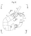
- Figs. 10 to 12 show the dilution section 17 in a configuration designed to supply a plant with a single-layer headbox. Equal numbers indicate parts identical or equivalent to those already described with reference to the embodiment of Figs 7, 8 and 9 . The difference between the two configurations lies in that in the second embodiment the dilution section 17 provides for a single descending tube 93 which is connected to the settling channel 91 for conveying the flow of raw waters to a centrifugal pump 99 (not shown in Figs. 10 to 12 for simplicity of representation) through a joint 95.
- the reference number 83 is still used to designate the pipe which feeds the raw waters from the area of formation of the paper to a possible air eliminator 85 connected to a vent 89 for the evacuation of air entrained by the raw waters coming from the forming wire.
- the air eliminator can be realized as disclosed with reference to Fig.14 .
- the section in Fig.13 shows the shape of the settling channel 91 the height of which is indicated with H and the width constituting the water passageway is indicated with L.
- 91A denotes an anti-foam plate, which retains the foam that forms on the free surface of the water discharged from the air eliminator 85, to prevent its entry into the settling channel 91, and make sure that within the tube 93 is supplied water as much as possible free of air bubbles and foam.
- the settling channel 91 has a curvilinear shape in plan, to increase the length of the path followed by the water between the first air eliminator 85 and the connection with the pipe 93 below. Along this path, the air that has not been separated from the water into the air eliminator 85 goes back on the water surface due to the air/water difference in density.
Landscapes
- Engineering & Computer Science (AREA)
- Life Sciences & Earth Sciences (AREA)
- Wood Science & Technology (AREA)
- Mechanical Engineering (AREA)
- Paper (AREA)
Priority Applications (1)
| Application Number | Priority Date | Filing Date | Title |
|---|---|---|---|
| PL13003626T PL2690216T3 (pl) | 2012-07-25 | 2013-07-18 | System do wytwarzania wstęgi celulozowej z zawiesiny wodnej włókien celulozowych |
Applications Claiming Priority (1)
| Application Number | Priority Date | Filing Date | Title |
|---|---|---|---|
| IT000154A ITFI20120154A1 (it) | 2012-07-25 | 2012-07-25 | Impianto per la produzione di materiale cellulosico tramite una sospensione acquosa di fibre |
Publications (2)
| Publication Number | Publication Date |
|---|---|
| EP2690216A1 true EP2690216A1 (fr) | 2014-01-29 |
| EP2690216B1 EP2690216B1 (fr) | 2016-02-10 |
Family
ID=46939767
Family Applications (1)
| Application Number | Title | Priority Date | Filing Date |
|---|---|---|---|
| EP13003626.2A Not-in-force EP2690216B1 (fr) | 2012-07-25 | 2013-07-18 | Système de production d'une bande de cellulose à partir d'une suspension aqueuse de fibres de cellulose |
Country Status (3)
| Country | Link |
|---|---|
| EP (1) | EP2690216B1 (fr) |
| IT (1) | ITFI20120154A1 (fr) |
| PL (1) | PL2690216T3 (fr) |
Cited By (1)
| Publication number | Priority date | Publication date | Assignee | Title |
|---|---|---|---|---|
| EP4477301A1 (fr) | 2023-06-09 | 2024-12-18 | Valmet Technologies Oy | Procédé de mélange de stock et système de mélange de stock |
Citations (5)
| Publication number | Priority date | Publication date | Assignee | Title |
|---|---|---|---|---|
| EP0969142A2 (fr) | 1998-06-29 | 2000-01-05 | Voith Sulzer Papiertechnik Patent GmbH | Procédé et dispositif pour mélanger des suspensions de pâte à papier |
| EP1126077A2 (fr) * | 2000-02-09 | 2001-08-22 | Voith Paper Patent GmbH | Procédé et dispositif pour la préparation de la pâte |
| DE102006008760A1 (de) * | 2006-02-24 | 2007-09-06 | Voith Patent Gmbh | Anordnung zur Zuführung von Stoffkomponenten in eine Papiermaschine |
| EP1884592A1 (fr) * | 2006-08-02 | 2008-02-06 | Voith Patent GmbH | Procédé destiné à l'introduction d'une suspension fibreuse dans une caisse de tête d'une machine à papier |
| WO2009103853A2 (fr) * | 2008-02-22 | 2009-08-27 | Wetend Technologies Oy | Procédé et dispositif pour le dosage proportionnel de pâte épaisse dans un circuit court d’une machine à bande de fibres |
-
2012
- 2012-07-25 IT IT000154A patent/ITFI20120154A1/it unknown
-
2013
- 2013-07-18 EP EP13003626.2A patent/EP2690216B1/fr not_active Not-in-force
- 2013-07-18 PL PL13003626T patent/PL2690216T3/pl unknown
Patent Citations (5)
| Publication number | Priority date | Publication date | Assignee | Title |
|---|---|---|---|---|
| EP0969142A2 (fr) | 1998-06-29 | 2000-01-05 | Voith Sulzer Papiertechnik Patent GmbH | Procédé et dispositif pour mélanger des suspensions de pâte à papier |
| EP1126077A2 (fr) * | 2000-02-09 | 2001-08-22 | Voith Paper Patent GmbH | Procédé et dispositif pour la préparation de la pâte |
| DE102006008760A1 (de) * | 2006-02-24 | 2007-09-06 | Voith Patent Gmbh | Anordnung zur Zuführung von Stoffkomponenten in eine Papiermaschine |
| EP1884592A1 (fr) * | 2006-08-02 | 2008-02-06 | Voith Patent GmbH | Procédé destiné à l'introduction d'une suspension fibreuse dans une caisse de tête d'une machine à papier |
| WO2009103853A2 (fr) * | 2008-02-22 | 2009-08-27 | Wetend Technologies Oy | Procédé et dispositif pour le dosage proportionnel de pâte épaisse dans un circuit court d’une machine à bande de fibres |
Cited By (2)
| Publication number | Priority date | Publication date | Assignee | Title |
|---|---|---|---|---|
| EP4477301A1 (fr) | 2023-06-09 | 2024-12-18 | Valmet Technologies Oy | Procédé de mélange de stock et système de mélange de stock |
| FI131615B1 (en) * | 2023-06-09 | 2025-08-07 | Valmet Technologies Oy | Stock mixing system |
Also Published As
| Publication number | Publication date |
|---|---|
| PL2690216T3 (pl) | 2016-07-29 |
| EP2690216B1 (fr) | 2016-02-10 |
| CN103572636A (zh) | 2014-02-12 |
| ITFI20120154A1 (it) | 2014-01-26 |
Similar Documents
| Publication | Publication Date | Title |
|---|---|---|
| FI89728C (fi) | Foerfarande och anlaeggning foer cirkulation av processvattnet i en pappersmaskin | |
| US8025772B2 (en) | Method for degassing and supplying a fibrous suspension to a headbox or a filter device and degassing device | |
| CN101435171B (zh) | 利用废渣生产再生纱管原纸的生产方法及其产品 | |
| SE428811B (sv) | Forfarande och anordning for framstellning av en flerskiktad pappersbana | |
| EP1007784B1 (fr) | Utilisation de pompes centrifuges lors de processus de production de bandes non-tisses avec adjonction de mousse | |
| AU667015B2 (en) | Papermaking process and apparatus for use therewith | |
| EP2690216B1 (fr) | Système de production d'une bande de cellulose à partir d'une suspension aqueuse de fibres de cellulose | |
| EP0793750B1 (fr) | Appareil et procede d'epuration d'une suspension fibreuse et procede de production de papier mettant en uvre ces derniers | |
| CN104404809A (zh) | 损纸浆处理装置 | |
| US20120048495A1 (en) | Approach flow system | |
| CN102182091A (zh) | 一种废纸脱墨制浆方法 | |
| JPH02127584A (ja) | ドロップ・レッグなどでの排出を容易にさせ且つその中でパルプを処理する方法及び装置 | |
| EP0466753B1 (fr) | Procede et appareil pour la filtration continue et le deplacement liquide d'une suspension liquide d'une matiere fibreuse ou finement divisee | |
| US6623156B1 (en) | Method for mixing a fluid mass | |
| CN217939447U (zh) | 一种多网过滤机白水回收系统 | |
| CN211645768U (zh) | 一种生产箱纸板的损纸处理系统 | |
| CN103572636B (zh) | 用于由纤维素纤维的水悬浮液生产纤维素幅材的系统 | |
| JP2766734B2 (ja) | 繊維分級装置付の白水回収システム | |
| CN221663272U (zh) | 一种用于纸浆脱水的设备 | |
| CN114875703A (zh) | 一种减少制浆过程中胶黏物的制浆系统及方法 | |
| CN102154895A (zh) | 利用白水回收机进行白水回收的方法 | |
| FI110796B (fi) | Menetelmä ilman poistamiseksi paperikoneen viiravesisäiliöstä ja vastaava viiravesisäiliö | |
| CN220927328U (zh) | 高效型除渣系统 | |
| CN212440092U (zh) | 一种新型淀粉刮刀滤液回收装置 | |
| FI105489B (fi) | Menetelmä ja laitteisto paperimassan esikäsittelemiseksi |
Legal Events
| Date | Code | Title | Description |
|---|---|---|---|
| PUAI | Public reference made under article 153(3) epc to a published international application that has entered the european phase |
Free format text: ORIGINAL CODE: 0009012 |
|
| AK | Designated contracting states |
Kind code of ref document: A1 Designated state(s): AL AT BE BG CH CY CZ DE DK EE ES FI FR GB GR HR HU IE IS IT LI LT LU LV MC MK MT NL NO PL PT RO RS SE SI SK SM TR |
|
| AX | Request for extension of the european patent |
Extension state: BA ME |
|
| 17P | Request for examination filed |
Effective date: 20140722 |
|
| RBV | Designated contracting states (corrected) |
Designated state(s): AL AT BE BG CH CY CZ DE DK EE ES FI FR GB GR HR HU IE IS IT LI LT LU LV MC MK MT NL NO PL PT RO RS SE SI SK SM TR |
|
| GRAP | Despatch of communication of intention to grant a patent |
Free format text: ORIGINAL CODE: EPIDOSNIGR1 |
|
| RIC1 | Information provided on ipc code assigned before grant |
Ipc: D21B 1/34 20060101AFI20150807BHEP Ipc: D21F 1/08 20060101ALI20150807BHEP Ipc: D21F 1/66 20060101ALI20150807BHEP |
|
| GRAJ | Information related to disapproval of communication of intention to grant by the applicant or resumption of examination proceedings by the epo deleted |
Free format text: ORIGINAL CODE: EPIDOSDIGR1 |
|
| GRAP | Despatch of communication of intention to grant a patent |
Free format text: ORIGINAL CODE: EPIDOSNIGR1 |
|
| INTG | Intention to grant announced |
Effective date: 20150915 |
|
| INTG | Intention to grant announced |
Effective date: 20150929 |
|
| GRAS | Grant fee paid |
Free format text: ORIGINAL CODE: EPIDOSNIGR3 |
|
| GRAA | (expected) grant |
Free format text: ORIGINAL CODE: 0009210 |
|
| AK | Designated contracting states |
Kind code of ref document: B1 Designated state(s): AL AT BE BG CH CY CZ DE DK EE ES FI FR GB GR HR HU IE IS IT LI LT LU LV MC MK MT NL NO PL PT RO RS SE SI SK SM TR |
|
| REG | Reference to a national code |
Ref country code: GB Ref legal event code: FG4D |
|
| REG | Reference to a national code |
Ref country code: AT Ref legal event code: REF Ref document number: 774714 Country of ref document: AT Kind code of ref document: T Effective date: 20160215 Ref country code: CH Ref legal event code: EP |
|
| REG | Reference to a national code |
Ref country code: IE Ref legal event code: FG4D |
|
| REG | Reference to a national code |
Ref country code: DE Ref legal event code: R096 Ref document number: 602013004959 Country of ref document: DE |
|
| REG | Reference to a national code |
Ref country code: SE Ref legal event code: TRGR |
|
| REG | Reference to a national code |
Ref country code: LT Ref legal event code: MG4D |
|
| REG | Reference to a national code |
Ref country code: NL Ref legal event code: MP Effective date: 20160210 |
|
| PG25 | Lapsed in a contracting state [announced via postgrant information from national office to epo] |
Ref country code: NO Free format text: LAPSE BECAUSE OF FAILURE TO SUBMIT A TRANSLATION OF THE DESCRIPTION OR TO PAY THE FEE WITHIN THE PRESCRIBED TIME-LIMIT Effective date: 20160510 Ref country code: GR Free format text: LAPSE BECAUSE OF FAILURE TO SUBMIT A TRANSLATION OF THE DESCRIPTION OR TO PAY THE FEE WITHIN THE PRESCRIBED TIME-LIMIT Effective date: 20160511 Ref country code: IT Free format text: LAPSE BECAUSE OF FAILURE TO SUBMIT A TRANSLATION OF THE DESCRIPTION OR TO PAY THE FEE WITHIN THE PRESCRIBED TIME-LIMIT Effective date: 20160210 Ref country code: ES Free format text: LAPSE BECAUSE OF FAILURE TO SUBMIT A TRANSLATION OF THE DESCRIPTION OR TO PAY THE FEE WITHIN THE PRESCRIBED TIME-LIMIT Effective date: 20160210 Ref country code: HR Free format text: LAPSE BECAUSE OF FAILURE TO SUBMIT A TRANSLATION OF THE DESCRIPTION OR TO PAY THE FEE WITHIN THE PRESCRIBED TIME-LIMIT Effective date: 20160210 |
|
| PG25 | Lapsed in a contracting state [announced via postgrant information from national office to epo] |
Ref country code: LT Free format text: LAPSE BECAUSE OF FAILURE TO SUBMIT A TRANSLATION OF THE DESCRIPTION OR TO PAY THE FEE WITHIN THE PRESCRIBED TIME-LIMIT Effective date: 20160210 Ref country code: PT Free format text: LAPSE BECAUSE OF FAILURE TO SUBMIT A TRANSLATION OF THE DESCRIPTION OR TO PAY THE FEE WITHIN THE PRESCRIBED TIME-LIMIT Effective date: 20160613 Ref country code: NL Free format text: LAPSE BECAUSE OF FAILURE TO SUBMIT A TRANSLATION OF THE DESCRIPTION OR TO PAY THE FEE WITHIN THE PRESCRIBED TIME-LIMIT Effective date: 20160210 Ref country code: LV Free format text: LAPSE BECAUSE OF FAILURE TO SUBMIT A TRANSLATION OF THE DESCRIPTION OR TO PAY THE FEE WITHIN THE PRESCRIBED TIME-LIMIT Effective date: 20160210 Ref country code: IS Free format text: LAPSE BECAUSE OF FAILURE TO SUBMIT A TRANSLATION OF THE DESCRIPTION OR TO PAY THE FEE WITHIN THE PRESCRIBED TIME-LIMIT Effective date: 20160610 Ref country code: RS Free format text: LAPSE BECAUSE OF FAILURE TO SUBMIT A TRANSLATION OF THE DESCRIPTION OR TO PAY THE FEE WITHIN THE PRESCRIBED TIME-LIMIT Effective date: 20160210 |
|
| PG25 | Lapsed in a contracting state [announced via postgrant information from national office to epo] |
Ref country code: DK Free format text: LAPSE BECAUSE OF FAILURE TO SUBMIT A TRANSLATION OF THE DESCRIPTION OR TO PAY THE FEE WITHIN THE PRESCRIBED TIME-LIMIT Effective date: 20160210 Ref country code: EE Free format text: LAPSE BECAUSE OF FAILURE TO SUBMIT A TRANSLATION OF THE DESCRIPTION OR TO PAY THE FEE WITHIN THE PRESCRIBED TIME-LIMIT Effective date: 20160210 |
|
| REG | Reference to a national code |
Ref country code: DE Ref legal event code: R097 Ref document number: 602013004959 Country of ref document: DE |
|
| PG25 | Lapsed in a contracting state [announced via postgrant information from national office to epo] |
Ref country code: SK Free format text: LAPSE BECAUSE OF FAILURE TO SUBMIT A TRANSLATION OF THE DESCRIPTION OR TO PAY THE FEE WITHIN THE PRESCRIBED TIME-LIMIT Effective date: 20160210 Ref country code: SM Free format text: LAPSE BECAUSE OF FAILURE TO SUBMIT A TRANSLATION OF THE DESCRIPTION OR TO PAY THE FEE WITHIN THE PRESCRIBED TIME-LIMIT Effective date: 20160210 Ref country code: RO Free format text: LAPSE BECAUSE OF FAILURE TO SUBMIT A TRANSLATION OF THE DESCRIPTION OR TO PAY THE FEE WITHIN THE PRESCRIBED TIME-LIMIT Effective date: 20160210 Ref country code: CZ Free format text: LAPSE BECAUSE OF FAILURE TO SUBMIT A TRANSLATION OF THE DESCRIPTION OR TO PAY THE FEE WITHIN THE PRESCRIBED TIME-LIMIT Effective date: 20160210 |
|
| PLBE | No opposition filed within time limit |
Free format text: ORIGINAL CODE: 0009261 |
|
| STAA | Information on the status of an ep patent application or granted ep patent |
Free format text: STATUS: NO OPPOSITION FILED WITHIN TIME LIMIT |
|
| PG25 | Lapsed in a contracting state [announced via postgrant information from national office to epo] |
Ref country code: BE Free format text: LAPSE BECAUSE OF FAILURE TO SUBMIT A TRANSLATION OF THE DESCRIPTION OR TO PAY THE FEE WITHIN THE PRESCRIBED TIME-LIMIT Effective date: 20160210 |
|
| 26N | No opposition filed |
Effective date: 20161111 |
|
| PG25 | Lapsed in a contracting state [announced via postgrant information from national office to epo] |
Ref country code: SI Free format text: LAPSE BECAUSE OF FAILURE TO SUBMIT A TRANSLATION OF THE DESCRIPTION OR TO PAY THE FEE WITHIN THE PRESCRIBED TIME-LIMIT Effective date: 20160210 Ref country code: BG Free format text: LAPSE BECAUSE OF FAILURE TO SUBMIT A TRANSLATION OF THE DESCRIPTION OR TO PAY THE FEE WITHIN THE PRESCRIBED TIME-LIMIT Effective date: 20160510 |
|
| REG | Reference to a national code |
Ref country code: CH Ref legal event code: PL |
|
| PG25 | Lapsed in a contracting state [announced via postgrant information from national office to epo] |
Ref country code: MC Free format text: LAPSE BECAUSE OF FAILURE TO SUBMIT A TRANSLATION OF THE DESCRIPTION OR TO PAY THE FEE WITHIN THE PRESCRIBED TIME-LIMIT Effective date: 20160210 |
|
| PG25 | Lapsed in a contracting state [announced via postgrant information from national office to epo] |
Ref country code: FR Free format text: LAPSE BECAUSE OF NON-PAYMENT OF DUE FEES Effective date: 20160801 Ref country code: LI Free format text: LAPSE BECAUSE OF NON-PAYMENT OF DUE FEES Effective date: 20160731 Ref country code: CH Free format text: LAPSE BECAUSE OF NON-PAYMENT OF DUE FEES Effective date: 20160731 |
|
| REG | Reference to a national code |
Ref country code: FR Ref legal event code: ST Effective date: 20170331 |
|
| REG | Reference to a national code |
Ref country code: IE Ref legal event code: MM4A |
|
| PG25 | Lapsed in a contracting state [announced via postgrant information from national office to epo] |
Ref country code: IE Free format text: LAPSE BECAUSE OF NON-PAYMENT OF DUE FEES Effective date: 20160718 |
|
| PG25 | Lapsed in a contracting state [announced via postgrant information from national office to epo] |
Ref country code: LU Free format text: LAPSE BECAUSE OF NON-PAYMENT OF DUE FEES Effective date: 20160718 |
|
| GBPC | Gb: european patent ceased through non-payment of renewal fee |
Effective date: 20170718 |
|
| PG25 | Lapsed in a contracting state [announced via postgrant information from national office to epo] |
Ref country code: GB Free format text: LAPSE BECAUSE OF NON-PAYMENT OF DUE FEES Effective date: 20170718 |
|
| PG25 | Lapsed in a contracting state [announced via postgrant information from national office to epo] |
Ref country code: CY Free format text: LAPSE BECAUSE OF FAILURE TO SUBMIT A TRANSLATION OF THE DESCRIPTION OR TO PAY THE FEE WITHIN THE PRESCRIBED TIME-LIMIT Effective date: 20160210 Ref country code: HU Free format text: LAPSE BECAUSE OF FAILURE TO SUBMIT A TRANSLATION OF THE DESCRIPTION OR TO PAY THE FEE WITHIN THE PRESCRIBED TIME-LIMIT; INVALID AB INITIO Effective date: 20130718 |
|
| PG25 | Lapsed in a contracting state [announced via postgrant information from national office to epo] |
Ref country code: TR Free format text: LAPSE BECAUSE OF FAILURE TO SUBMIT A TRANSLATION OF THE DESCRIPTION OR TO PAY THE FEE WITHIN THE PRESCRIBED TIME-LIMIT Effective date: 20160210 Ref country code: MK Free format text: LAPSE BECAUSE OF FAILURE TO SUBMIT A TRANSLATION OF THE DESCRIPTION OR TO PAY THE FEE WITHIN THE PRESCRIBED TIME-LIMIT Effective date: 20160210 Ref country code: MT Free format text: LAPSE BECAUSE OF NON-PAYMENT OF DUE FEES Effective date: 20160731 |
|
| REG | Reference to a national code |
Ref country code: AT Ref legal event code: UEP Ref document number: 774714 Country of ref document: AT Kind code of ref document: T Effective date: 20160210 |
|
| PG25 | Lapsed in a contracting state [announced via postgrant information from national office to epo] |
Ref country code: AL Free format text: LAPSE BECAUSE OF FAILURE TO SUBMIT A TRANSLATION OF THE DESCRIPTION OR TO PAY THE FEE WITHIN THE PRESCRIBED TIME-LIMIT Effective date: 20160210 |
|
| PGFP | Annual fee paid to national office [announced via postgrant information from national office to epo] |
Ref country code: SE Payment date: 20220720 Year of fee payment: 10 Ref country code: FI Payment date: 20220721 Year of fee payment: 10 Ref country code: DE Payment date: 20220720 Year of fee payment: 10 Ref country code: AT Payment date: 20220721 Year of fee payment: 10 |
|
| PGFP | Annual fee paid to national office [announced via postgrant information from national office to epo] |
Ref country code: PL Payment date: 20220711 Year of fee payment: 10 |
|
| REG | Reference to a national code |
Ref country code: DE Ref legal event code: R119 Ref document number: 602013004959 Country of ref document: DE |
|
| REG | Reference to a national code |
Ref country code: SE Ref legal event code: EUG |
|
| REG | Reference to a national code |
Ref country code: AT Ref legal event code: MM01 Ref document number: 774714 Country of ref document: AT Kind code of ref document: T Effective date: 20230718 |
|
| PG25 | Lapsed in a contracting state [announced via postgrant information from national office to epo] |
Ref country code: AT Free format text: LAPSE BECAUSE OF NON-PAYMENT OF DUE FEES Effective date: 20230718 |
|
| PG25 | Lapsed in a contracting state [announced via postgrant information from national office to epo] |
Ref country code: FI Free format text: LAPSE BECAUSE OF NON-PAYMENT OF DUE FEES Effective date: 20230718 Ref country code: DE Free format text: LAPSE BECAUSE OF NON-PAYMENT OF DUE FEES Effective date: 20240201 Ref country code: AT Free format text: LAPSE BECAUSE OF NON-PAYMENT OF DUE FEES Effective date: 20230718 |
|
| PG25 | Lapsed in a contracting state [announced via postgrant information from national office to epo] |
Ref country code: SE Free format text: LAPSE BECAUSE OF NON-PAYMENT OF DUE FEES Effective date: 20230719 |
|
| PG25 | Lapsed in a contracting state [announced via postgrant information from national office to epo] |
Ref country code: PL Free format text: LAPSE BECAUSE OF NON-PAYMENT OF DUE FEES Effective date: 20230718 |
|
| PG25 | Lapsed in a contracting state [announced via postgrant information from national office to epo] |
Ref country code: PL Free format text: LAPSE BECAUSE OF NON-PAYMENT OF DUE FEES Effective date: 20230718 |