EP2690290B1 - Zentrifugalverdichter mit schneckengehäuse - Google Patents
Zentrifugalverdichter mit schneckengehäuse Download PDFInfo
- Publication number
- EP2690290B1 EP2690290B1 EP12763192.7A EP12763192A EP2690290B1 EP 2690290 B1 EP2690290 B1 EP 2690290B1 EP 12763192 A EP12763192 A EP 12763192A EP 2690290 B1 EP2690290 B1 EP 2690290B1
- Authority
- EP
- European Patent Office
- Prior art keywords
- scroll
- fluid
- cross
- velocity
- degrees
- Prior art date
- Legal status (The legal status is an assumption and is not a legal conclusion. Google has not performed a legal analysis and makes no representation as to the accuracy of the status listed.)
- Active
Links
Images



Classifications
-
- F—MECHANICAL ENGINEERING; LIGHTING; HEATING; WEAPONS; BLASTING
- F04—POSITIVE - DISPLACEMENT MACHINES FOR LIQUIDS; PUMPS FOR LIQUIDS OR ELASTIC FLUIDS
- F04D—NON-POSITIVE-DISPLACEMENT PUMPS
- F04D29/00—Details, component parts, or accessories
- F04D29/40—Casings; Connections of working fluid
- F04D29/42—Casings; Connections of working fluid for radial or helico-centrifugal pumps
- F04D29/4206—Casings; Connections of working fluid for radial or helico-centrifugal pumps especially adapted for elastic fluid pumps
-
- F—MECHANICAL ENGINEERING; LIGHTING; HEATING; WEAPONS; BLASTING
- F04—POSITIVE - DISPLACEMENT MACHINES FOR LIQUIDS; PUMPS FOR LIQUIDS OR ELASTIC FLUIDS
- F04D—NON-POSITIVE-DISPLACEMENT PUMPS
- F04D29/00—Details, component parts, or accessories
- F04D29/40—Casings; Connections of working fluid
- F04D29/403—Casings; Connections of working fluid especially adapted for elastic fluid pumps
-
- F—MECHANICAL ENGINEERING; LIGHTING; HEATING; WEAPONS; BLASTING
- F04—POSITIVE - DISPLACEMENT MACHINES FOR LIQUIDS; PUMPS FOR LIQUIDS OR ELASTIC FLUIDS
- F04D—NON-POSITIVE-DISPLACEMENT PUMPS
- F04D29/00—Details, component parts, or accessories
- F04D29/40—Casings; Connections of working fluid
- F04D29/42—Casings; Connections of working fluid for radial or helico-centrifugal pumps
- F04D29/4206—Casings; Connections of working fluid for radial or helico-centrifugal pumps especially adapted for elastic fluid pumps
- F04D29/4226—Fan casings
-
- F—MECHANICAL ENGINEERING; LIGHTING; HEATING; WEAPONS; BLASTING
- F04—POSITIVE - DISPLACEMENT MACHINES FOR LIQUIDS; PUMPS FOR LIQUIDS OR ELASTIC FLUIDS
- F04D—NON-POSITIVE-DISPLACEMENT PUMPS
- F04D29/00—Details, component parts, or accessories
- F04D29/40—Casings; Connections of working fluid
- F04D29/42—Casings; Connections of working fluid for radial or helico-centrifugal pumps
- F04D29/44—Fluid-guiding means, e.g. diffusers
- F04D29/441—Fluid-guiding means, e.g. diffusers especially adapted for elastic fluid pumps
-
- F—MECHANICAL ENGINEERING; LIGHTING; HEATING; WEAPONS; BLASTING
- F04—POSITIVE - DISPLACEMENT MACHINES FOR LIQUIDS; PUMPS FOR LIQUIDS OR ELASTIC FLUIDS
- F04D—NON-POSITIVE-DISPLACEMENT PUMPS
- F04D29/00—Details, component parts, or accessories
- F04D29/66—Combating cavitation, whirls, noise, vibration or the like; Balancing
- F04D29/68—Combating cavitation, whirls, noise, vibration or the like; Balancing by influencing boundary layers
- F04D29/681—Combating cavitation, whirls, noise, vibration or the like; Balancing by influencing boundary layers especially adapted for elastic fluid pumps
-
- F—MECHANICAL ENGINEERING; LIGHTING; HEATING; WEAPONS; BLASTING
- F05—INDEXING SCHEMES RELATING TO ENGINES OR PUMPS IN VARIOUS SUBCLASSES OF CLASSES F01-F04
- F05D—INDEXING SCHEME FOR ASPECTS RELATING TO NON-POSITIVE-DISPLACEMENT MACHINES OR ENGINES, GAS-TURBINES OR JET-PROPULSION PLANTS
- F05D2250/00—Geometry
- F05D2250/50—Inlet or outlet
- F05D2250/52—Outlet
Definitions
- the present invention relates to a centrifugal compressor comprising a scroll portion which constitutes a flow path formed by rotation of a compressor impeller in a spiral shape in an outer peripheral portion of the compressor impeller, and to a scroll shape which enables recovery of static pressure of a fluid (gas) in the scroll portion.
- Centrifugal compressors are required to have high pressure and high efficiency over a wide operating range.
- FIG. 7 shows an enlarged sectional view of a substantial part of an upper half of an axis of a rotary shaft of a compressor impeller in a centrifugal compressor.
- a compressor 1 of a centrifugal compressor mainly comprises a compressor impeller 3 constituted by a rotating hub 31 and a large number of centrifugal vanes 32 attached to an outer circumferential surface of the hub 31, a shaft 2 coupled to a rotary drive source of the compressor impeller 3, and a compressor housing 11 which houses the compressor impeller 3 and the shaft 2 and which forms a flow path of a fluid.
- the compressor housing 11 is provided with a diffuser portion 13 which forms a roughly donut shape on an outer circumferential side of the compressor impeller 3 and which enables recovery of static pressure by decreasing the velocity of fluid that is discharged from the compressor impeller 3, a scroll portion 12 which is formed on an outer circumferential side of the diffuser portion 13 so that a cross-sectional area of the scroll portion 12 spirally increases in a circumferential direction and which collects gas over the entire circumference, and an outlet tube (not shown).
- a diffuser portion 13 which forms a roughly donut shape on an outer circumferential side of the compressor impeller 3 and which enables recovery of static pressure by decreasing the velocity of fluid that is discharged from the compressor impeller 3, a scroll portion 12 which is formed on an outer circumferential side of the diffuser portion 13 so that a cross-sectional area of the scroll portion 12 spirally increases in a circumferential direction and which collects gas over the entire circumference, and an outlet tube (not shown).
- the centrifugal vanes 32 compress a fluid such as a gas or air introduced from an air passageway 15.
- a flow (fluid) of gas or air or the like formed in this manner proceeds from an outer circumferential end of the compressor impeller 3, passes through the diffuser portion 13 and the scroll portion 12, and is sent out from the outlet tube.
- FIG. 8 is a schematic diagram showing an example of the scroll portion 12 in plan view.
- the scroll portion 12 has a constant distribution of a radius R (a centroid P 0 of a cross section of the cross section 12 and an axis L1 of the shaft 2) for positions determined at intervals of 30 degrees in a clockwise direction from a position of 60 degrees, where an end point (360 degrees in FIG. 8 ) of the scroll is set as a 0 base.
- FIG. 9A shows a constant distribution of a radius R, wherein angle positions in a circumferential direction are plotted on a horizontal axis and the radius R from an axis L1 of a rotary shaft of the compressor of the scroll portion 12 to a centroid P of a scroll cross section is plotted on a vertical axis.
- FIG. 9B is a cross-sectional view in which cross sections at respective circumferential positions (at intervals of 30 degrees) of the scroll portion 12 when a position at 60 degrees in a clockwise direction in FIG. 8 is set as a base are laminated on top of each other, and shows a variation of a centroid P 0 of the scroll cross section in a direction of the radius R.
- each cross-sectional area of the scroll portion 12 increases at a constant rate ⁇ in a flowing direction of the fluid in accordance with an amount of inflow of the fluid.
- Fluid velocity in the scroll becomes constant when equilibrium is established between the enlargement rate ⁇ (constant rate) of the cross-sectional area of the scroll portion 12 and a rate of increase of the amount of fluid inflow into the scroll portion 12 from the diffuser portion 13.
- Patent Document 1 discloses conventional art in which a shape of a scroll is varied.
- a first transition portion in which a cross-sectional area of a scroll portion comprising a flow path formed in a spiral shape around a rotary shaft of rotor blades of a turbine which produces power by supplying a fluid gas to the rotor blades gradually decreases while a cross-sectional shape of the scroll portion transitions from a square shape with rounded corners to a circular shape, wherein curvature radii of the corner portions of the first transition portion are essentially set to a same magnitude.
- the technique disclosed enables a sufficient cross-sectional area of the flow path to be secured in each phase and pressure loss of the fluid to be reduced.
- Patent Document 1 is related to a scroll shape of a turbine which produces power by supplying a fluid gas to rotor blades and expanding the fluid gas, and differs from the present application in which a fluid (gas) is compressed with respect to how a fluid flows and in fluid characteristics.
- centrifugal compressors are required to have a high pressure ratio and high efficiency over a wide range.
- JPS60135696 , JP2010216378 and US5624229 each disclose a centrifugal compressor comprising a scroll which forms a flow path of a fluid from a diffuser portion arranged on a downstream-side of the compressor impeller, wherein the cross-sectional area A of a scroll portion and the radius from an axis of the compressor impeller to a centroid of a cross section of the scroll portion both vary over the circumference of the winding of the scroll.
- the velocity of the fluid in the scroll portion can conceivably be decreased by linearly increasing (increasing at a constant ratio) a size of cross sections of the scroll portion.
- a boundary layer between the fluid and a wall surface of the scroll portion increases and prevents sufficient static pressure recovery, and an occurrence of surging results in defects such as a reduction in an operating range and a decline in turbocharging efficiency.
- the present invention has been made in order to solve such problems, and an object of the present invention is to enable a centrifugal compressor to produce high efficiency and high pressure by gradually increasing an enlargement rate in which a cross-sectional area of a scroll portion is enlarged from a tongue portion to an arbitrary angle in a circumferential direction of the scroll portion from an enlargement rate in accordance with an increase in an inflow amount of a fluid flowing through the scroll portion and subsequently reducing the enlargement rate of the cross-sectional area from the arbitrary angle to a winding end of the scroll portion in order to create a portion in which the velocity of the flow of the fluid in the scroll is decreased and a portion in which the velocity of the flow of the fluid in the scroll is increased to ensure sufficient static pressure recovery.
- the present invention provides a centrifugal compressor comprising a scroll which forms a flow path of a fluid such as a gas or air discharged from a diffuser portion arranged on a downstream-side of a compressor impeller of the centrifugal compressor, wherein an enlargement rate of a ratio A/R of a cross-sectional area A of a scroll portion to a radius R from an axis of the compressor impeller to a centroid of a cross section of the scroll portion due to an increase in a scroll angle in a circumferential flow direction, named here-after "cross-sectional area enlargement rate", decreases from a first arbitrary angle to a winding end of the scroll portion.
- the ratio A/R is calculated as a sum of ratios Ai/ri of cross-sectional areas Ai and a constant radius ri when the cross section of the scroll portion is divided into band-like regions with the constant radius ri and the cross-sectional area Ai.
- a highly accurate volumetric flow rate of a fluid is calculated to reduce fluid velocity and recover pressure, and by increasing the fluid velocity near a winding end of the scroll, development of a boundary layer between a wall surface of the scroll portion and the fluid is prevented to reduce losses (decrease flow rate resistance and improve pressure ratio) and stabilize flow.
- the present invention further comprises a velocity decrease region in which the cross-sectional area of the scroll portion from a tongue portion of the scroll portion to a second arbitrary angle in a winding direction of the scroll portion gradually increases in order to decrease a velocity of the fluid and a velocity increase region which decreases a rate of enlargement of the ratio A/R from the second arbitrary angle to a winding end of the scroll portion to below the rate of the velocity decrease region in order to increase the velocity of the fluid.
- the distribution of A/R of the scroll cross section when a distribution of A/R of the scroll cross section is displayed on coordinate axes including a horizontal axis which increases in a rightward direction from the winding start to the winding end of the scroll portion and a vertical axis on which the ratio A/R of the cross-sectional area A to the scroll radius R increases in an upward direction, the distribution of A/R has an upward convex shape.
- the second arbitrary angle is within a range of 300 to 330 degrees in a flowing direction of the fluid in the scroll when the winding end of the scroll is set as a 0 (zero) base.
- the rate of enlargement of the ratio A/R of the scroll portion in a vicinity of the tongue portion is set lower than in the velocity decrease region.
- the region in which the cross-sectional area in the vicinity of the tongue portion is decreased to below the ratio of the velocity decrease region is within approximately 30 to 60 degrees in the scroll direction from the tongue portion.
- a radius of a centroid of the cross section and a radius of a center of the scroll portion are varied while keeping the enlargement ratio of the cross-sectional area of the scroll portion constant in order to decrease the velocity of the fluid flowing through the scroll portion.
- the radius of the centroid of the cross section of the scroll portion and a radius of a center of the scroll portion are kept constant while the enlargement rate of the cross-sectional area is varied in order to decrease the velocity of the fluid flowing through the scroll portion.
- a scroll according to the present invention comprises a fluid flow path constituted by a diffuser portion 13 which forms a roughly donut shape on an outer circumferential side of a compressor impeller 3 and which enables recovery of static pressure by decreasing the velocity of fluid (gas) that is discharged from the compressor impeller 3, a scroll portion 12 which is formed on an outer circumferential side of the diffuser portion 13 so that a cross-sectional area of the scroll portion 12 spirally increases in a winding direction (a flowing direction of the fluid) and which decreases velocity and increases pressure of the fluid, and an outlet tube (not shown).
- centrifugal vanes 32 compress a fluid such as a gas or air introduced from an air passageway 15.
- a flow of the fluid (gas) formed in this manner proceeds from an outer circumferential end of the compressor impeller 3, passes through the diffuser portion 13 and the scroll portion 12, and is sent out from the outlet tube.
- FIGS. 1, 2 , 3A, 3B, and 3C A scroll shape of a centrifugal compressor according to the first embodiment of the present invention will be described with reference to FIGS. 1, 2 , 3A, 3B, and 3C .
- FIG. 1 shows the scroll portion 12 in plan view.
- the scroll shape is roughly circular in a cross section in a radial direction of the scroll portion 12, and an area of the cross section gradually increases in a spiral shape from a position at 60 degrees in the winding direction to an end point Z (360 degrees) of the scroll portion, with the end point Z of the scroll portion is set as a 0 base (hereinafter, it is to be understood that a "cross section of the scroll portion” refers to a cross section in a direction perpendicular to an axis line of an air passageway in the scroll portion 12).
- a tongue portion 5 which is a portion approximately consistent with a winding start position of the scroll portion 12 and which is an end edge of a partition between fluid discharged from the diffuser portion 13 and fluid having flowed through the scroll is arranged near a position at approximately 60 degrees in the winding direction shown in FIG. 1 .
- the scroll portion 12 has a velocity decrease region ⁇ in which a velocity of the fluid is decreased to recover static pressure and a velocity increase region ⁇ in which the velocity of the fluid is increased to stabilize flowage.
- a velocity of a fluid is greater on an inner side than on an outer side in a cross section of each portion of the scroll portion 12.
- a volumetric flow rate Q of the fluid flowing through the scroll portion 12 must take a size (shape) of the cross section and a radius of the scroll into consideration.
- volumetric flow rate Q can be determined using the following equation by dividing a scroll cross section into band-like regions (cross-sectional area Ai) with a constant radius of ri as shown in FIG. 2 according to equation (1).
- V ⁇ i ⁇ ri V ⁇ r is satisfied from equation (1).
- v ⁇ i v ⁇ r r i
- V ⁇ r represents a velocity in an outer circumferential portion of the diffuser 13 of a fluid discharged from the compressor impeller 3 and is constant over the entire outer circumferential portion of the diffuser 13, V ⁇ r can be considered a constant (that is determined upon design).
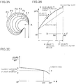
- FIG. 3A is a sectional view displaying cross sections of the scroll portion at respective portions in a winding direction (the flowing direction of the fluid) laminated on top of each other according to the present embodiment.
- FIG. 3A represents a distribution when a cross-sectional area enlargement rate of A/R is varied and laminates cross sections of respective portions ⁇ 1, ⁇ 2, ⁇ 3, ⁇ 4, ⁇ 5, and ⁇ 6 in the circumferential direction of the scroll shown in FIG. 1 .
- Fluid (gas) from the compressor impeller 3 flows into the scroll portion 12 via the diffuser portion 13 over approximately the entire circumference of the scroll portion 12.
- A/R of each cross section of the scroll portion 12 is adjusted by increasing or decreasing a cross-sectional area enlargement rate (d(A/R)/d ⁇ ) associated with an increase in scroll angle and setting a constant enlargement rate based on a conventional scroll design in accordance with an inflow amount of fluid flowing through the scroll portion 12 as a base rate ⁇ (threshold).
- a magnitude of an interval between respective layers represents a magnitude of the area enlargement rate.
- FIG. 3B is a diagram in which ⁇ indicating an angle in the winding direction of the scroll is plotted on a horizontal axis and a ratio of A/R representing a size of a cross sectional area is plotted on a vertical axis, and which shows a fluid velocity characteristic curve E which is a velocity decreasing characteristic of fluid whose velocity decreases and increases as A/R varies.
- FIG. 3C represents A/R of the vertical axis in FIG. 3B as the cross-sectional area enlargement rate (d(A/R)/d ⁇ ) of a cross section.
- a region from ⁇ 1 (60 degrees) to 300 degrees is considered to be a velocity decrease region ⁇ which, in the case of FIG. 1 , ranges from ⁇ 1 to ⁇ 5.
- a cross-sectional area enlargement rate ⁇ of the velocity decrease region ⁇ is set higher than the base rate ⁇ (threshold) that is a constant value depicted by a dashed line in FIG. 3C in order to reduce fluid velocity and recover static pressure.
- a region from 300 degrees to a winding end of the scroll at 360 degrees is considered to be a velocity increase region ⁇ , and a cross-sectional area enlargement rate ⁇ of the velocity decrease region ⁇ is set lower than the cross-sectional area enlargement rate ⁇ in order to increase fluid velocity.
- the cross-sectional area enlargement rate (d(A/R)/d ⁇ ) has a magnitude of ⁇ > ⁇ > ⁇ .
- the velocity of the fluid in the scroll portion 12 decreases as the cross-sectional area increases (based on the description of equation (5)), and by setting the cross-sectional area enlargement rate ⁇ of A/R lower than ⁇ between 300 degrees and 360 degrees (the winding end of the scroll), the velocity of the fluid is increased. Accordingly, as shown in FIG. 3B , the fluid velocity characteristic curve E becomes a velocity decreasing characteristic with an upward convex shape, and a static pressure recovery portion and a velocity increase portion are formed in the scroll portion 12.
- the cross-sectional area enlargement rate (d(A/R)/d ⁇ ) shown in FIG. 3C shows a downward-sloping trend, in the direction toward the right side of the figure, from the winding start to the winding end of the scroll portion.
- a region between scroll angles 60 degrees and 300 degrees in which the cross-sectional area enlargement rate has a greater value than the constant-value base rate ⁇ shown as conventional in FIG. 3C is the velocity decrease region, and a region between 300 degrees and 360 degrees in which the cross-sectional area enlargement rate has a smaller value is the velocity increase region.
- ⁇ 1 (60 degrees) to 300 degrees which define the velocity decrease region ⁇ and 300 degrees to the winding end of the scroll at 360 degrees which define the velocity increase region ⁇ are not limited thereto.
- a portion in which fluid velocity is increased at the winding end portion (360 degrees) of the scroll is set to 30 degrees in order to expand a region in which A/R increases and to maximize static pressure recovery of the fluid.
- a basic shape is the same as that of the first embodiment with the sole exception of the shape of the scroll portion 12 which forms a flow path of a fluid such as gas or air discharged from the diffuser portion 13 that is arranged on a downstream side of the compressor impeller 3 of a centrifugal compressor, only the scroll portion 12 will be described and descriptions of other components will be omitted.
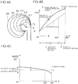
- FIG. 4A is a sectional view displaying cross sections of the scroll portion at respective portions ⁇ 1, ⁇ 2, ⁇ 3, ⁇ 4, ⁇ 5, and ⁇ 6 in a winding direction of the scroll (the flowing direction of the fluid) shown in FIG. 1 laminated on top of each other according to the present embodiment.
- FIG. 4A represents a case where a centroid radius R of A/R is varied, in which ⁇ 1 (60 degrees) to 300 degrees forms a velocity decrease region ⁇ of A/R and 300 degrees to the winding end of the scroll at 360 degrees forms a velocity increase region ⁇ .
- FIG. 4A P 0 represents a centroid of a cross section of each scroll portion 12 and a solid line with a mountain shape represents a variation in positions of the centroid P 0 in each cross section of the scroll portion.
- FIG. 4B is a diagram in which ⁇ indicating an angle in the winding direction of the scroll is plotted on a horizontal axis and A/R is plotted on a vertical axis, and which shows a fluid velocity characteristic curve F in which the fluid velocity decreases as the degree of increase of A/R varies.
- fluid (gas) from the compressor impeller 3 flows into the scroll portion 12 via the diffuser portion 13 over approximately the entire circumference of the scroll portion 12.
- ⁇ 1 (60 degrees) to 300 degrees in which radius increases forms the velocity decrease region ( ⁇ ) which approximately corresponds to a region in which the cross-sectional area enlargement rate is set higher than the base enlargement rate ⁇ .
- the fluid velocity characteristic curve F according to the present embodiment is a curve (an upward-convex curve in FIG. 4B ) representing an increase and a decrease of the velocity of the fluid in the flowing direction of the fluid (winding direction) of the scroll portion 12.
- the centroid radius is reduced in the flowing direction of the fluid between 300 degrees and 360 degrees (the winding end of the scroll) to form a curve representing an increase in velocity of the fluid (in FIG. 4B , the incline of the upward slope becomes less sharp and the cross-sectional area enlargement rate falls below the base enlargement rate ⁇ in FIG. 4C ).
- the entire fluid velocity characteristic curve F becomes a velocity decreasing characteristic with an upward convex shape, and a static pressure recovery portion and a velocity increase portion are formed in the scroll portion 12.
- ⁇ 1 (60 degrees) to 300 degrees which define the velocity decrease region ⁇ (enlargement of A/R) and 300 degrees to the winding end of the scroll at 360 degrees which define the velocity increase region ⁇ are not limited thereto.
- a portion in which fluid velocity is increased at the winding end portion (360 degrees) of the scroll is set to 60 degrees (300 degrees to 360 degrees) in order to expand a region in which A/R is increased to maximize static pressure recovery of the fluid.
- a basic shape is the same as that of the first embodiment with the sole exception of the shape of the scroll portion 12 of a centrifugal compressor which forms a flow path of a fluid such as gas or air discharged from a diffuser portion arranged on a downstream side of a compressor impeller of the centrifugal compressor, only the scroll portion 12 will be described and descriptions of other components will be omitted.
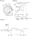
- FIG. 5A is a sectional view displaying cross sections of the scroll portion at respective portions in a winding direction of the scroll (the flowing direction of the fluid) laminated on top of each other according to the present embodiment.
- FIG. 5A shows the lamination of cross sections of respective portions ⁇ 1, ⁇ 2, ⁇ 3, ⁇ 4, ⁇ 5, and ⁇ 6 in the circumferential direction of the scroll shown in FIG. 1 .
- a tongue portion 5 which is a portion approximately consistent with a winding start position of the scroll and which is an end edge of a partition between fluid discharged from the diffuser portion 13 and fluid having flowed through the scroll is arranged near a position at approximately 60 degrees in the flowing direction of the fluid shown in FIG. 1 .
- ⁇ 1 which denotes a cross section of the scroll portion represents a cross-sectional area of the tongue portion 5, wherein a conventional cross-sectional shape is depicted by a dashed line and a cross-sectional shape according to the present application is depicted by a solid line.
- a separation occurs between the tongue portion 5 and the fluid near the tongue portion 5 due to the influence of the tongue portion 5.
- FIG. 5B is a diagram in which an angle ⁇ in the winding direction of the scroll is plotted on a horizontal axis and an area A of A/R is plotted on a vertical axis, and which shows a fluid velocity characteristic curve G in which the fluid velocity decreases as the area A of A/R increases.
- FIG. 5C is a diagram in which cross-sectional area enlargement rate (d(A/R)/d ⁇ ) is plotted on the vertical axis of FIG. 5B .
- a region from about 120 degrees in the winding direction of the scroll to the winding end is the same as that of the first embodiment, and by setting A/R or d(A/R)/d ⁇ higher than a conventional base rate, a velocity decrease region ⁇ is formed and fluid velocity is reduced.
- the cross-sectional area enlargement rate is set lower than that in the region from 120 degrees to 300 degrees to form a velocity increase region ⁇ in which fluid velocity is increased.
- FIG. 5B a region between scroll angles 60 degrees to 120 degrees is represented by a downward-convex graph and a region where the scroll angle is equal to or larger than 120 degrees is represented by an upward-convex graph in a similar manner to FIG. 3B .
- regions from 60 degrees to 120 degrees and from 300 degrees to 360 degrees represent velocity increase regions having values smaller than conventional values and a region from 120 degrees to 300 degrees forms an upward-convex graph in which values are greater than conventional values.
- the numerical values of ⁇ 1 (60 degrees) to 120 degrees which define the first velocity increase region ⁇ of the tongue portion, 120 degrees to 300 degrees which define the velocity decrease region ⁇ , and 300 degrees to the winding end of the scroll at 360 degrees which define a second velocity increase region ⁇ are not limited thereto.
- a basic shape is the same as that of the second embodiment with the sole exception of the shape of the scroll portion 12 of a centrifugal compressor which forms a flow path of a fluid such as gas or air discharged from a diffuser portion arranged on a downstream side of a compressor impeller of the centrifugal compressor, only the scroll portion 12 will be described and descriptions of other components will be omitted.
- FIG. 6A is a sectional view according to the present embodiment which represents a case where a centroid radius R of A/R is varied and which shows cross sections of the scroll portion at respective portions ⁇ 1, ⁇ 2, ⁇ 3, ⁇ 4, ⁇ 5, and ⁇ 6 in a winding direction of the scroll (the flowing direction of the fluid) shown in FIG. 1 laminated on top of each other.
- FIG. 6B is a diagram in which ⁇ indicating an angle in the winding direction of the scroll is plotted on a horizontal axis and a radius R of A/R is plotted on a vertical axis, and which shows a fluid velocity characteristic curve H in accordance with a variation in the radius R of A/R.
- the radius R of a conventional centroid P 0 is constant (dashed line) at respective portions in the winding direction of the scroll.
- ⁇ 1 which denotes a cross section of the scroll portion represents a cross-sectional area of the tongue portion 5, wherein a conventional cross-sectional shape is depicted by a dashed line and a cross-sectional shape according to the present embodiment is depicted by a solid line.
- FIG. 6B a region between scroll angles 60 degrees to 120 degrees is represented by a downward-convex graph and a region where the scroll angle is equal to or larger than 120 degrees is represented by an upward-convex graph in a similar manner to FIG. 3B .
- regions from 60 degrees to 120 degrees and from 300 degrees to 360 degrees represent velocity increase regions having values smaller than conventional values and a region from 120 degrees to 300 degrees forms an upward-convex graph in which values are greater than conventional values.
- FIG. 6B is a diagram in which an angle ⁇ in the winding direction of the scroll (the flowing direction of the fluid) is plotted on a horizontal axis and A/R is plotted on a vertical axis, and which shows a fluid velocity characteristic curve H in which the fluid velocity decreases as the enlargement rate of A/R increases.
- FIG. 6C is a diagram in which cross-sectional area enlargement rate (d(A/R)/d ⁇ ) is plotted on the vertical axis of FIG. 6B .
- the fluid velocity of the portion is increased to resolve the separation between the tongue portion 5 and the fluid.
- Means of reducing the cross-sectional area A between approximately 60 degrees to 120 degrees near the tongue portion 5 include a method of reducing a radially-inner portion of the cross section ⁇ 1 as shown in FIG. 5A .
- a region between approximately 120 degrees in the winding direction of the scroll to the winding end is the same as that according to the second embodiment, wherein by setting the cross-sectional area enlargement rate higher than the base rate ⁇ while increasing the centroid R in the flowing direction of the fluid, a velocity decrease region ⁇ is formed and fluid velocity is reduced.
- a second velocity increase region ⁇ is formed in which the velocity of the fluid is increased.
- the present invention relates to a centrifugal compressor comprising a scroll portion shape which constitutes a flow path formed in a spiral shape in an outer peripheral portion of a compressor impeller due to the rotation of the compressor impeller, and is favorably used in a centrifugal compressor which enables recovery of static pressure in the scroll portion to obtain high compressor performance.
Landscapes
- Engineering & Computer Science (AREA)
- Mechanical Engineering (AREA)
- General Engineering & Computer Science (AREA)
- Structures Of Non-Positive Displacement Pumps (AREA)
Claims (6)
- Ein Zentrifugalkompressor (1), aufweisend eine Schnecke (12), welche einen Flussweg eines Fluids ausbildet, wie zum Beispiel ein Gas oder Luft, welches von einem Diffusorteil (13) ausgestoßen wird, welcher an einer stromabwärtigen Seite des Kompressorlaufrads (3) des Zentrifugalkompressors (1) angeordnet ist,
dadurch gekennzeichnet, dass
ein Vergrößerungsverhältnis eines Verhältnisses A/R einer Querschnittsfläche A eines Schneckenteils (12) zu einem Radius R von einer Achse (2) des Kompressorlaufrads (3) zu einem Schwerpunkt (P0) eines Querschnitts des Schneckenteils (12), aufgrund einer Vergrößerung eines Schneckenwinkels in einer umfänglichen Fluidflussrichtung, sich verringert von einem ersten beliebigen Winkel zu einem Windungsende des Schneckenteils (12). - Zentrifugalkompressor (1) gemäß Anspruch 1, wobei das Verhältnis A/R berechnet wird als eine Summe von Verhältnissen Ai/Ri der Querschnittsflächen Ai und einem konstanten Radius Ri, wenn der Querschnitt des Schneckenteils (12) aufgeteilt wird in bandähnliche Bereiche mit dem konstanten Radius Ri und der Querschnittsfläche Ai.
- Zentrifugalkompressor (1) gemäß Anspruch 1, weiter aufweisend einen Geschwindigkeitsverringerungsbereich (α, γ), bei welchem sich der Querschnittsbereich des Schneckenteils von einem Zungenteil (5) des Schneckenteils (12) zu einem zweiten beliebigen Winkel in einer Windungsrichtung des Schneckenteils fortschreitend vergrößert, um eine Geschwindigkeit des Fluids zu verringern, und einen Geschwindigkeitsvergrößerungsbereich (β, δ), bei welchem sich ein Vergrößerungsverhältnis des Verhältnisses A/R von dem zweiten beliebigen Winkel zu einem Windungsende des Schneckenteils verringert bis unterhalb des Verhältnisses des Geschwindigkeitsverringerungsbereichs, um die Geschwindigkeit des Fluids zu vergrößern.
- Zentrifugalkompressor (1) gemäß einem der Ansprüche 1 bis 3, wobei, wenn eine Verteilung von A/R des Schneckenquerschnitts dargestellt wird auf Koordinatenachsen, beinhaltend eine horizontale Achse, welche sich in einer Richtung nach rechts von dem Windungsbeginn zu dem Windungsende des Schneckenteils vergrößert, und eine vertikale Achse, bei welcher sich das Verhältnis A/R der Querschnittsfläche A zu dem Schneckenradius R vergrößert in einer nach oben gerichteten Richtung, die Verteilung von A/R eine nach oben konvexe Form aufweist.
- Zentrifugalkompressor (1) gemäß Anspruch 3, wobei der zweite beliebige Winkel in einem Bereich von 300 bis 330 Grad in einer Flussrichtung des Fluids in der Schnecke (12) ist, wenn das Windungsende der Schnecke (12) als eine o (Null) Basis eingestellt ist.
- Zentrifugalkompressor gemäß Anspruch 1, wobei das Vergrößerungsverhältnis des Verhältnisses A/R des Schneckenteils sich in einer Nähe des Zungenteils vergrößert in der Flussrichtung des Fluids.
Applications Claiming Priority (2)
| Application Number | Priority Date | Filing Date | Title |
|---|---|---|---|
| JP2011068490A JP5439423B2 (ja) | 2011-03-25 | 2011-03-25 | 遠心圧縮機のスクロール形状 |
| PCT/JP2012/051892 WO2012132528A1 (ja) | 2011-03-25 | 2012-01-27 | 遠心圧縮機のスクロール形状 |
Publications (3)
| Publication Number | Publication Date |
|---|---|
| EP2690290A1 EP2690290A1 (de) | 2014-01-29 |
| EP2690290A4 EP2690290A4 (de) | 2014-12-17 |
| EP2690290B1 true EP2690290B1 (de) | 2018-01-10 |
Family
ID=46930295
Family Applications (1)
| Application Number | Title | Priority Date | Filing Date |
|---|---|---|---|
| EP12763192.7A Active EP2690290B1 (de) | 2011-03-25 | 2012-01-27 | Zentrifugalverdichter mit schneckengehäuse |
Country Status (5)
| Country | Link |
|---|---|
| US (1) | US9366265B2 (de) |
| EP (1) | EP2690290B1 (de) |
| JP (1) | JP5439423B2 (de) |
| CN (1) | CN103443472B (de) |
| WO (1) | WO2012132528A1 (de) |
Families Citing this family (12)
| Publication number | Priority date | Publication date | Assignee | Title |
|---|---|---|---|---|
| WO2017072900A1 (ja) * | 2015-10-29 | 2017-05-04 | 三菱重工業株式会社 | スクロールケーシング及び遠心圧縮機 |
| JP6642711B2 (ja) | 2016-07-01 | 2020-02-12 | 株式会社Ihi | 遠心圧縮機 |
| WO2018003632A1 (ja) | 2016-07-01 | 2018-01-04 | 株式会社Ihi | 遠心圧縮機 |
| CN110234888B (zh) * | 2017-03-28 | 2022-09-27 | 三菱重工发动机和增压器株式会社 | 压缩机的涡旋形状以及增压器 |
| US11073164B2 (en) * | 2017-11-06 | 2021-07-27 | Mitsubishi Heavy Industries Engine & Turbocharger, Ltd. | Centrifugal compressor and turbocharger including the same |
| US11060529B2 (en) | 2017-11-20 | 2021-07-13 | Mitsubishi Heavy Industries Engine & Turbocharger, Ltd. | Centrifugal compressor and turbocharger including the same |
| CN108374792B (zh) * | 2018-01-12 | 2019-09-20 | 清华大学 | 一种采用蜗壳流道截面A/r非线性分布的离心压气机 |
| US11131236B2 (en) * | 2019-03-13 | 2021-09-28 | Garrett Transportation I Inc. | Turbocharger having adjustable-trim centrifugal compressor including divergent-wall diffuser |
| DE112019006986T5 (de) * | 2019-05-24 | 2021-11-25 | Mitsubishi Heavy Industries Engine & Turbocharger, Ltd. | Zentrifugalkompressor und Turbolader |
| DE112019007061T5 (de) * | 2019-05-30 | 2021-12-16 | Mitsubishi Heavy Industries Engine & Turbocharger, Ltd. | Zentrifugalkompressor und turbolader |
| US12031546B2 (en) * | 2020-04-17 | 2024-07-09 | Mitsubishi Heavy Industries Engine & Turbocharger, Ltd. | Scroll casing and centrifugal compressor |
| CN114439773B (zh) * | 2022-01-05 | 2023-07-18 | 东风柳州汽车有限公司 | 一种水泵结构及发动机 |
Family Cites Families (18)
| Publication number | Priority date | Publication date | Assignee | Title |
|---|---|---|---|---|
| US3848040A (en) * | 1969-04-17 | 1974-11-12 | Corning Glass Works | Apparatus and method for forming slii cast bodies with cavities |
| JPS60135696A (ja) * | 1983-12-26 | 1985-07-19 | Hitachi Ltd | 多段圧縮機の水平分割形溶接構造ケ−シング |
| JPH03217699A (ja) * | 1990-01-23 | 1991-09-25 | Nissan Motor Co Ltd | 圧縮機のスクロール構造 |
| CN1059959A (zh) * | 1990-09-15 | 1992-04-01 | 列宁“夫斯基工厂”生产联合公司 | 离心式压缩机 |
| DE4331606C1 (de) * | 1993-09-17 | 1994-10-06 | Gutehoffnungshuette Man | Spiralgehäuse für Turbomaschinen |
| JP3442885B2 (ja) * | 1994-12-20 | 2003-09-02 | 東芝キヤリア株式会社 | 遠心送風機 |
| JP3632789B2 (ja) * | 1995-08-28 | 2005-03-23 | 東陶機器株式会社 | 多翼遠心ファンの設計方法及び多翼遠心ファン |
| JP2001263019A (ja) | 2000-03-22 | 2001-09-26 | Sanshin Ind Co Ltd | エンジン用オイルポンプ駆動構造 |
| JP2003217699A (ja) * | 2002-01-18 | 2003-07-31 | Yazaki Corp | 圧接端子及び配線板 |
| JP4492045B2 (ja) * | 2003-06-13 | 2010-06-30 | 株式会社Ihi | 遠心圧縮機 |
| KR20060035477A (ko) | 2004-10-22 | 2006-04-26 | 엘지전자 주식회사 | 원심팬의 토출구 형성구조 |
| JP4435713B2 (ja) * | 2005-04-21 | 2010-03-24 | 株式会社ケーヒン | 遠心式送風機 |
| JP4952006B2 (ja) * | 2006-03-07 | 2012-06-13 | 株式会社デンソー | 遠心式送風機 |
| JP5110288B2 (ja) | 2008-03-14 | 2012-12-26 | 株式会社Ihi | 過給機 |
| JP2010138752A (ja) * | 2008-12-10 | 2010-06-24 | Toyota Motor Corp | コンプレッサ及びそれを備えた内燃機関のターボチャージャ |
| JP5163904B2 (ja) | 2009-03-11 | 2013-03-13 | 株式会社Ihi | スクロール部構造及び過給機 |
| JP5204016B2 (ja) * | 2009-03-17 | 2013-06-05 | 株式会社神戸製鋼所 | ターボ圧縮機 |
| JP5517914B2 (ja) | 2010-12-27 | 2014-06-11 | 三菱重工業株式会社 | 遠心圧縮機のスクロール構造 |
-
2011
- 2011-03-25 JP JP2011068490A patent/JP5439423B2/ja not_active Expired - Fee Related
-
2012
- 2012-01-27 US US13/978,897 patent/US9366265B2/en not_active Expired - Fee Related
- 2012-01-27 CN CN201280013796.3A patent/CN103443472B/zh active Active
- 2012-01-27 WO PCT/JP2012/051892 patent/WO2012132528A1/ja not_active Ceased
- 2012-01-27 EP EP12763192.7A patent/EP2690290B1/de active Active
Non-Patent Citations (1)
| Title |
|---|
| None * |
Also Published As
| Publication number | Publication date |
|---|---|
| JP5439423B2 (ja) | 2014-03-12 |
| CN103443472A (zh) | 2013-12-11 |
| US20130294903A1 (en) | 2013-11-07 |
| EP2690290A4 (de) | 2014-12-17 |
| CN103443472B (zh) | 2017-05-17 |
| US9366265B2 (en) | 2016-06-14 |
| EP2690290A1 (de) | 2014-01-29 |
| JP2012202323A (ja) | 2012-10-22 |
| WO2012132528A1 (ja) | 2012-10-04 |
Similar Documents
| Publication | Publication Date | Title |
|---|---|---|
| EP2690290B1 (de) | Zentrifugalverdichter mit schneckengehäuse | |
| EP2392830B1 (de) | Laufrad für einen zentrifugalverdichter | |
| JP2012202323A5 (de) | ||
| US8475131B2 (en) | Centrifugal compressor | |
| CN103261702B (zh) | 离心压缩机的涡旋构造 | |
| RU2581686C2 (ru) | Радиальная диффузорная лопатка для центробежных компрессоров | |
| CN101868630B (zh) | 离心压缩机的翼型扩压器 | |
| EP1741935A1 (de) | Radialverdichter und verfahren zur laufradherstellung | |
| US9039374B2 (en) | Turbine rotor | |
| US8317466B2 (en) | Blade structure of gas turbine | |
| JP5517914B2 (ja) | 遠心圧縮機のスクロール構造 | |
| KR20150082562A (ko) | 만곡된 복귀 채널 베인을 갖는 원심 압축기 | |
| JP2011021492A (ja) | インペラおよび回転機械 | |
| KR20110131252A (ko) | 터빈 휠 | |
| JP2016061241A (ja) | 遠心羽根車及び遠心圧縮機 | |
| JP4949882B2 (ja) | 遠心圧縮機のインペラ及び遠心圧縮機 | |
| EP4112944B1 (de) | Laufrad und zentrifugalverdichter | |
| EP3421810B1 (de) | Laufrad für radialverdichter | |
| EP3561311B1 (de) | Verdichterspiralenform und -auflader | |
| JP6876146B2 (ja) | 遠心圧縮機及びこの遠心圧縮機を備えたターボチャージャ | |
| US6273672B1 (en) | Two-phase helical mixed flow impeller with curved fairing | |
| US6382919B1 (en) | Two-phase impeller with curved channel in the meridian plane | |
| US11428240B2 (en) | Centrifugal compressor and turbocharger including the same |
Legal Events
| Date | Code | Title | Description |
|---|---|---|---|
| PUAI | Public reference made under article 153(3) epc to a published international application that has entered the european phase |
Free format text: ORIGINAL CODE: 0009012 |
|
| 17P | Request for examination filed |
Effective date: 20130703 |
|
| AK | Designated contracting states |
Kind code of ref document: A1 Designated state(s): AL AT BE BG CH CY CZ DE DK EE ES FI FR GB GR HR HU IE IS IT LI LT LU LV MC MK MT NL NO PL PT RO RS SE SI SK SM TR |
|
| DAX | Request for extension of the european patent (deleted) | ||
| A4 | Supplementary search report drawn up and despatched |
Effective date: 20141118 |
|
| RIC1 | Information provided on ipc code assigned before grant |
Ipc: F04D 29/42 20060101ALI20141112BHEP Ipc: F04D 29/44 20060101AFI20141112BHEP Ipc: F04D 29/68 20060101ALI20141112BHEP |
|
| GRAP | Despatch of communication of intention to grant a patent |
Free format text: ORIGINAL CODE: EPIDOSNIGR1 |
|
| INTG | Intention to grant announced |
Effective date: 20170920 |
|
| GRAS | Grant fee paid |
Free format text: ORIGINAL CODE: EPIDOSNIGR3 |
|
| GRAA | (expected) grant |
Free format text: ORIGINAL CODE: 0009210 |
|
| AK | Designated contracting states |
Kind code of ref document: B1 Designated state(s): AL AT BE BG CH CY CZ DE DK EE ES FI FR GB GR HR HU IE IS IT LI LT LU LV MC MK MT NL NO PL PT RO RS SE SI SK SM TR |
|
| REG | Reference to a national code |
Ref country code: CH Ref legal event code: EP Ref country code: AT Ref legal event code: REF Ref document number: 962727 Country of ref document: AT Kind code of ref document: T Effective date: 20180115 |
|
| REG | Reference to a national code |
Ref country code: IE Ref legal event code: FG4D |
|
| REG | Reference to a national code |
Ref country code: DE Ref legal event code: R096 Ref document number: 602012041960 Country of ref document: DE |
|
| REG | Reference to a national code |
Ref country code: FR Ref legal event code: PLFP Year of fee payment: 7 |
|
| REG | Reference to a national code |
Ref country code: NL Ref legal event code: FP |
|
| REG | Reference to a national code |
Ref country code: AT Ref legal event code: MK05 Ref document number: 962727 Country of ref document: AT Kind code of ref document: T Effective date: 20180110 |
|
| PG25 | Lapsed in a contracting state [announced via postgrant information from national office to epo] |
Ref country code: NO Free format text: LAPSE BECAUSE OF FAILURE TO SUBMIT A TRANSLATION OF THE DESCRIPTION OR TO PAY THE FEE WITHIN THE PRESCRIBED TIME-LIMIT Effective date: 20180410 Ref country code: FI Free format text: LAPSE BECAUSE OF FAILURE TO SUBMIT A TRANSLATION OF THE DESCRIPTION OR TO PAY THE FEE WITHIN THE PRESCRIBED TIME-LIMIT Effective date: 20180110 Ref country code: CY Free format text: LAPSE BECAUSE OF FAILURE TO SUBMIT A TRANSLATION OF THE DESCRIPTION OR TO PAY THE FEE WITHIN THE PRESCRIBED TIME-LIMIT Effective date: 20180110 Ref country code: ES Free format text: LAPSE BECAUSE OF FAILURE TO SUBMIT A TRANSLATION OF THE DESCRIPTION OR TO PAY THE FEE WITHIN THE PRESCRIBED TIME-LIMIT Effective date: 20180110 Ref country code: LT Free format text: LAPSE BECAUSE OF FAILURE TO SUBMIT A TRANSLATION OF THE DESCRIPTION OR TO PAY THE FEE WITHIN THE PRESCRIBED TIME-LIMIT Effective date: 20180110 Ref country code: HR Free format text: LAPSE BECAUSE OF FAILURE TO SUBMIT A TRANSLATION OF THE DESCRIPTION OR TO PAY THE FEE WITHIN THE PRESCRIBED TIME-LIMIT Effective date: 20180110 |
|
| PG25 | Lapsed in a contracting state [announced via postgrant information from national office to epo] |
Ref country code: GR Free format text: LAPSE BECAUSE OF FAILURE TO SUBMIT A TRANSLATION OF THE DESCRIPTION OR TO PAY THE FEE WITHIN THE PRESCRIBED TIME-LIMIT Effective date: 20180411 Ref country code: BG Free format text: LAPSE BECAUSE OF FAILURE TO SUBMIT A TRANSLATION OF THE DESCRIPTION OR TO PAY THE FEE WITHIN THE PRESCRIBED TIME-LIMIT Effective date: 20180410 Ref country code: RS Free format text: LAPSE BECAUSE OF FAILURE TO SUBMIT A TRANSLATION OF THE DESCRIPTION OR TO PAY THE FEE WITHIN THE PRESCRIBED TIME-LIMIT Effective date: 20180110 Ref country code: AT Free format text: LAPSE BECAUSE OF FAILURE TO SUBMIT A TRANSLATION OF THE DESCRIPTION OR TO PAY THE FEE WITHIN THE PRESCRIBED TIME-LIMIT Effective date: 20180110 Ref country code: LV Free format text: LAPSE BECAUSE OF FAILURE TO SUBMIT A TRANSLATION OF THE DESCRIPTION OR TO PAY THE FEE WITHIN THE PRESCRIBED TIME-LIMIT Effective date: 20180110 Ref country code: SE Free format text: LAPSE BECAUSE OF FAILURE TO SUBMIT A TRANSLATION OF THE DESCRIPTION OR TO PAY THE FEE WITHIN THE PRESCRIBED TIME-LIMIT Effective date: 20180110 Ref country code: IS Free format text: LAPSE BECAUSE OF FAILURE TO SUBMIT A TRANSLATION OF THE DESCRIPTION OR TO PAY THE FEE WITHIN THE PRESCRIBED TIME-LIMIT Effective date: 20180510 Ref country code: PL Free format text: LAPSE BECAUSE OF FAILURE TO SUBMIT A TRANSLATION OF THE DESCRIPTION OR TO PAY THE FEE WITHIN THE PRESCRIBED TIME-LIMIT Effective date: 20180110 |
|
| REG | Reference to a national code |
Ref country code: CH Ref legal event code: PL |
|
| REG | Reference to a national code |
Ref country code: DE Ref legal event code: R097 Ref document number: 602012041960 Country of ref document: DE |
|
| PG25 | Lapsed in a contracting state [announced via postgrant information from national office to epo] |
Ref country code: EE Free format text: LAPSE BECAUSE OF FAILURE TO SUBMIT A TRANSLATION OF THE DESCRIPTION OR TO PAY THE FEE WITHIN THE PRESCRIBED TIME-LIMIT Effective date: 20180110 Ref country code: RO Free format text: LAPSE BECAUSE OF FAILURE TO SUBMIT A TRANSLATION OF THE DESCRIPTION OR TO PAY THE FEE WITHIN THE PRESCRIBED TIME-LIMIT Effective date: 20180110 Ref country code: IT Free format text: LAPSE BECAUSE OF FAILURE TO SUBMIT A TRANSLATION OF THE DESCRIPTION OR TO PAY THE FEE WITHIN THE PRESCRIBED TIME-LIMIT Effective date: 20180110 Ref country code: LU Free format text: LAPSE BECAUSE OF NON-PAYMENT OF DUE FEES Effective date: 20180127 Ref country code: MC Free format text: LAPSE BECAUSE OF FAILURE TO SUBMIT A TRANSLATION OF THE DESCRIPTION OR TO PAY THE FEE WITHIN THE PRESCRIBED TIME-LIMIT Effective date: 20180110 Ref country code: AL Free format text: LAPSE BECAUSE OF FAILURE TO SUBMIT A TRANSLATION OF THE DESCRIPTION OR TO PAY THE FEE WITHIN THE PRESCRIBED TIME-LIMIT Effective date: 20180110 |
|
| REG | Reference to a national code |
Ref country code: IE Ref legal event code: MM4A |
|
| REG | Reference to a national code |
Ref country code: BE Ref legal event code: MM Effective date: 20180131 |
|
| PLBE | No opposition filed within time limit |
Free format text: ORIGINAL CODE: 0009261 |
|
| STAA | Information on the status of an ep patent application or granted ep patent |
Free format text: STATUS: NO OPPOSITION FILED WITHIN TIME LIMIT |
|
| PG25 | Lapsed in a contracting state [announced via postgrant information from national office to epo] |
Ref country code: SK Free format text: LAPSE BECAUSE OF FAILURE TO SUBMIT A TRANSLATION OF THE DESCRIPTION OR TO PAY THE FEE WITHIN THE PRESCRIBED TIME-LIMIT Effective date: 20180110 Ref country code: LI Free format text: LAPSE BECAUSE OF NON-PAYMENT OF DUE FEES Effective date: 20180131 Ref country code: DK Free format text: LAPSE BECAUSE OF FAILURE TO SUBMIT A TRANSLATION OF THE DESCRIPTION OR TO PAY THE FEE WITHIN THE PRESCRIBED TIME-LIMIT Effective date: 20180110 Ref country code: CH Free format text: LAPSE BECAUSE OF NON-PAYMENT OF DUE FEES Effective date: 20180131 Ref country code: SM Free format text: LAPSE BECAUSE OF FAILURE TO SUBMIT A TRANSLATION OF THE DESCRIPTION OR TO PAY THE FEE WITHIN THE PRESCRIBED TIME-LIMIT Effective date: 20180110 Ref country code: BE Free format text: LAPSE BECAUSE OF NON-PAYMENT OF DUE FEES Effective date: 20180131 Ref country code: CZ Free format text: LAPSE BECAUSE OF FAILURE TO SUBMIT A TRANSLATION OF THE DESCRIPTION OR TO PAY THE FEE WITHIN THE PRESCRIBED TIME-LIMIT Effective date: 20180110 |
|
| 26N | No opposition filed |
Effective date: 20181011 |
|
| PG25 | Lapsed in a contracting state [announced via postgrant information from national office to epo] |
Ref country code: IE Free format text: LAPSE BECAUSE OF NON-PAYMENT OF DUE FEES Effective date: 20180127 |
|
| PG25 | Lapsed in a contracting state [announced via postgrant information from national office to epo] |
Ref country code: SI Free format text: LAPSE BECAUSE OF FAILURE TO SUBMIT A TRANSLATION OF THE DESCRIPTION OR TO PAY THE FEE WITHIN THE PRESCRIBED TIME-LIMIT Effective date: 20180110 |
|
| PG25 | Lapsed in a contracting state [announced via postgrant information from national office to epo] |
Ref country code: MT Free format text: LAPSE BECAUSE OF NON-PAYMENT OF DUE FEES Effective date: 20180127 |
|
| PG25 | Lapsed in a contracting state [announced via postgrant information from national office to epo] |
Ref country code: TR Free format text: LAPSE BECAUSE OF FAILURE TO SUBMIT A TRANSLATION OF THE DESCRIPTION OR TO PAY THE FEE WITHIN THE PRESCRIBED TIME-LIMIT Effective date: 20180110 |
|
| PG25 | Lapsed in a contracting state [announced via postgrant information from national office to epo] |
Ref country code: HU Free format text: LAPSE BECAUSE OF FAILURE TO SUBMIT A TRANSLATION OF THE DESCRIPTION OR TO PAY THE FEE WITHIN THE PRESCRIBED TIME-LIMIT; INVALID AB INITIO Effective date: 20120127 Ref country code: PT Free format text: LAPSE BECAUSE OF FAILURE TO SUBMIT A TRANSLATION OF THE DESCRIPTION OR TO PAY THE FEE WITHIN THE PRESCRIBED TIME-LIMIT Effective date: 20180110 |
|
| PG25 | Lapsed in a contracting state [announced via postgrant information from national office to epo] |
Ref country code: MK Free format text: LAPSE BECAUSE OF NON-PAYMENT OF DUE FEES Effective date: 20180110 |
|
| PGFP | Annual fee paid to national office [announced via postgrant information from national office to epo] |
Ref country code: NL Payment date: 20201214 Year of fee payment: 10 |
|
| REG | Reference to a national code |
Ref country code: NL Ref legal event code: MM Effective date: 20220201 |
|
| PG25 | Lapsed in a contracting state [announced via postgrant information from national office to epo] |
Ref country code: NL Free format text: LAPSE BECAUSE OF NON-PAYMENT OF DUE FEES Effective date: 20220201 |
|
| PGFP | Annual fee paid to national office [announced via postgrant information from national office to epo] |
Ref country code: GB Payment date: 20221208 Year of fee payment: 12 Ref country code: FR Payment date: 20221208 Year of fee payment: 12 |
|
| GBPC | Gb: european patent ceased through non-payment of renewal fee |
Effective date: 20240127 |
|
| PG25 | Lapsed in a contracting state [announced via postgrant information from national office to epo] |
Ref country code: GB Free format text: LAPSE BECAUSE OF NON-PAYMENT OF DUE FEES Effective date: 20240127 |
|
| PG25 | Lapsed in a contracting state [announced via postgrant information from national office to epo] |
Ref country code: FR Free format text: LAPSE BECAUSE OF NON-PAYMENT OF DUE FEES Effective date: 20240131 |
|
| PG25 | Lapsed in a contracting state [announced via postgrant information from national office to epo] |
Ref country code: GB Free format text: LAPSE BECAUSE OF NON-PAYMENT OF DUE FEES Effective date: 20240127 Ref country code: FR Free format text: LAPSE BECAUSE OF NON-PAYMENT OF DUE FEES Effective date: 20240131 |
|
| PGFP | Annual fee paid to national office [announced via postgrant information from national office to epo] |
Ref country code: DE Payment date: 20251203 Year of fee payment: 15 |