EP2690476A1 - Dispositif à objectif - Google Patents
Dispositif à objectif Download PDFInfo
- Publication number
- EP2690476A1 EP2690476A1 EP12761516.9A EP12761516A EP2690476A1 EP 2690476 A1 EP2690476 A1 EP 2690476A1 EP 12761516 A EP12761516 A EP 12761516A EP 2690476 A1 EP2690476 A1 EP 2690476A1
- Authority
- EP
- European Patent Office
- Prior art keywords
- lens
- guide shafts
- imaging device
- support holes
- lens apparatus
- Prior art date
- Legal status (The legal status is an assumption and is not a legal conclusion. Google has not performed a legal analysis and makes no representation as to the accuracy of the status listed.)
- Withdrawn
Links
- 238000003384 imaging method Methods 0.000 claims abstract description 34
- 229910052782 aluminium Inorganic materials 0.000 claims description 15
- XAGFODPZIPBFFR-UHFFFAOYSA-N aluminium Chemical group [Al] XAGFODPZIPBFFR-UHFFFAOYSA-N 0.000 claims description 15
- 230000003287 optical effect Effects 0.000 claims description 14
- 230000037431 insertion Effects 0.000 claims description 4
- 238000003780 insertion Methods 0.000 claims description 4
- 239000000463 material Substances 0.000 claims description 4
- 239000004033 plastic Substances 0.000 claims description 4
- 238000005452 bending Methods 0.000 claims description 3
- 230000007246 mechanism Effects 0.000 description 4
- 238000010276 construction Methods 0.000 description 3
- JOYRKODLDBILNP-UHFFFAOYSA-N Ethyl urethane Chemical compound CCOC(N)=O JOYRKODLDBILNP-UHFFFAOYSA-N 0.000 description 1
- 239000004677 Nylon Substances 0.000 description 1
- 229930182556 Polyacetal Natural products 0.000 description 1
- 230000000694 effects Effects 0.000 description 1
- 229910052751 metal Inorganic materials 0.000 description 1
- 239000002184 metal Substances 0.000 description 1
- 229920001778 nylon Polymers 0.000 description 1
- 230000002093 peripheral effect Effects 0.000 description 1
- 229920006324 polyoxymethylene Polymers 0.000 description 1
- 238000005476 soldering Methods 0.000 description 1
Images



Classifications
-
- G—PHYSICS
- G02—OPTICS
- G02B—OPTICAL ELEMENTS, SYSTEMS OR APPARATUS
- G02B7/00—Mountings, adjusting means, or light-tight connections, for optical elements
- G02B7/02—Mountings, adjusting means, or light-tight connections, for optical elements for lenses
- G02B7/04—Mountings, adjusting means, or light-tight connections, for optical elements for lenses with mechanism for focusing or varying magnification
-
- G—PHYSICS
- G02—OPTICS
- G02B—OPTICAL ELEMENTS, SYSTEMS OR APPARATUS
- G02B7/00—Mountings, adjusting means, or light-tight connections, for optical elements
- G02B7/02—Mountings, adjusting means, or light-tight connections, for optical elements for lenses
-
- G—PHYSICS
- G02—OPTICS
- G02B—OPTICAL ELEMENTS, SYSTEMS OR APPARATUS
- G02B7/00—Mountings, adjusting means, or light-tight connections, for optical elements
- G02B7/02—Mountings, adjusting means, or light-tight connections, for optical elements for lenses
- G02B7/021—Mountings, adjusting means, or light-tight connections, for optical elements for lenses for more than one lens
Definitions
- the present invention relates to a lens apparatus in which a lens holder is movable along plural guide shafts.
- a lens apparatus is attached to a camera body in an optical instrument, for example, a camera such as a surveillance camera, broadcast camera and the like.
- movable lenses such as a focus lens, zooming lens and the like are disposed movably in an optical axis direction.
- a known example of moving mechanism for a movable lens includes a lens holder for holding the movable lens, and two guide shafts extending in an optical axis direction for supporting the lens holder movably.
- the lens holder has a guide portion with an axial hole, and an anti-rotation portion of a fork shape, and is received on respectively the guide shafts in a slidable manner.
- the guide portion has a greater length than the anti-rotation portion in order to prevent offsetting.
- the guide portion is received on the discrete guide shafts to enable two adjacent lens holders to come near.
- Patent document 1 discloses the lens apparatus in which a lens housing of a box shape is used and two guide shafts are secured to the lens housing.
- the lens housing has front and rear plates extending perpendicularly to the optical axis. Two quadrilateral holes of a small size are formed in the front plate. Two quadrilateral holes of a large size are formed in the rear plate. Front ends of the two guide shafts are inserted through the quadrilateral holes of the rear plate, and press-fitted in the quadrilateral holes of the front plates. A pad member is fitted in the quadrilateral holes of the rear plate, and presses the rear end of the guide shafts to two side lines of the quadrilateral holes to position the guide shafts.
- Patent Document 1 Japanese Patent Laid-open Publication No. 2010-066713
- the pad member for positioning the guide shafts is inserted in a rear side of an engagement portion of the lens housing by resiliently deforming an engagement projection of an upper end of the pad member. As the pad member is not firmly secured to the lens housing, it is likely that the pad member may drop from the lens housing during transport of the lens apparatus in an individual state before assembly in the camera body.
- An object of the present invention is to provide a lens apparatus in which a pad member is kept from dropping from a lens housing without using a special fixing member.
- a plurality of lens holders for holding lenses, a plurality of guide shafts, a lens housing having front and rear plates, a plurality of first support holes formed in the rear plate, a plurality of second support holes formed in the front plate, a plurality of shaft pad members secured to the first support holes, and an imaging device retaining member.
- the plurality of guide shafts are disposed in parallel with a direction of an optical axis of the lenses, for supporting the lens holders movably.
- the plurality of first support holes have a larger size than the guide shafts.
- the plurality of second support holes are for receiving press-fit of a front end of the guide shafts inserted through the first support holes.
- the plurality of shaft pad members are inserted in respectively the first support holes, for contacting a rear end surface of the guide shafts, and pushing an outer surface of the guide shafts perpendicularly to the optical axis.
- the imaging device retaining member retains an imaging device for imaging of an image formed by a plurality of the lenses, the imaging device retaining member being fixed on the rear plate in a state overlapped on the shaft pad members.
- the shaft pad members have a body and a projection formed to project from the body, the body partially contacts a rear end surface of the guide shafts, the projection partially pushes an outer surface of the guide shafts perpendicularly to the optical axis.
- the first support holes have a channel portion for fitting in of an edge of the body and a quadrilateral through hole for receiving insertion of the projection.
- the projection is in an A-shape, and a link portion thereof presses a portion of an outer surface of the guide shafts, and presses a remaining portion of the outer surface of the guide shafts to two side lines of the quadrilateral through hole.
- the body of the shaft pad member becomes flush with the rear plate when an edge of the body is engaged with the channel portion of the first support holes.
- the shaft pad members are formed from resilient plastic material.
- the body has a pad portion formed by bending partially in a U shape, and becomes deformed to absorb surplus force of push when the pad portion is pressed by the imaging device retaining member.
- Plural circular bosses are formed with the pad portion for receiving the imaging device retaining member.
- the imaging device retaining member is an aluminum plate to which the imaging device is secured.
- the imaging device retaining member is a circuit board with which the imaging device is connected.
- the rear of the shaft pad member is pushed by the imaging device retaining member secured to the lens housing.
- the shaft pad member is kept from dropping during transport of the lens apparatus.
- no special part is necessary for preventing drop of the shaft pad member, so that the structure can be simple and the cost can be low.
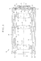
- a lens apparatus 10 is used for a surveillance camera, and includes first, second and third lens groups 12, 13 and 14 (hereinafter referred to as lenses) or three constituting a focusing optical system.
- the first to third lenses although depicted as single lens elements in the drawings, are actually constituted by a plurality of lens elements.
- the first lens 12 is a variator lens for changing a focal length.
- the third lens 14 is a focus lens for focus adjustment.
- the first and third lenses move along an optical axis 28.
- the second lens 13 is a relay lens fixed in an immovable manner. At the time of zooming, the first lens 12 moves to change an image magnification. At the time of focus adjustment, the third lens 14 moves. Note that the first lens 12 and the third lens 4 move for the zooming.
- the first to third lenses 12-14 are mounted in lens holders 16, 17 and 18.
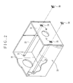
- a lens housing 20 contains the lens holders 16-18.
- the lens holder 17 is fixed in the lens housing 20.
- Two guide shafts 25 and 26 parallel with the optical axis 28 are secured to the lens housing 20.
- In the lens holders 16 and 18 are formed guide holes 21 and 22 with a predetermined ensured length, and guide grooves 23 and 24 for anti-rotation purpose.
- the guide holes 21 and 22 and the guide grooves 23 and 24 for anti-rotation purpose are engaged with the guide shafts 25 and 26 in a movable manner in an optical axis direction.
- lens holder moving mechanisms are disposed for respectively the lens holders 16 and 18.
- Each of the lens holder moving mechanisms includes a stepping motor and a feed screw rotated by the stepping motor.
- Each feed screw is engaged helically with a nut formed on the lens holders 16 and 18.
- the stepping motor rotates.
- the lens holders 16 and 18 move along the guide shafts 25 and 26 according to the combination of the feed screw and the nut. Note that the lens holders 16 and 18 may be moved by a known cam mechanism.
- the guide shaft 25 is penetrated through a first support hole 34, a hole 36 and the guide hole 21 serially, the first support hole 34 being formed in a rear plate 33 of the lens housing 20, the hole 36 being formed in the lens holder 17, the guide hole 21 being formed in the lens holder 16. After this, a front end 41 of the guide shaft 25 is press-fitted in a second support hole 31 formed in a front plate 30. Before securing the guide shaft 26, the guide groove 24 formed in the lens holder 18 is engaged with the guide shaft 25.
- the guide shaft 26 is penetrated through a first support hole 34, the guide hole 22, a hole 37 and the guide groove 23 serially, the first support hole 34 being formed in the rear plate 33, the guide hole 22 being formed in the lens holder 18, the hole 37 being formed in the lens holder 17, the guide groove 23 being formed in the lens holder 16.
- a front end 42 of the guide shaft 26 is press-fitted in a second support hole 32 formed in the front plate 30.
- the guide shafts 25 and 26 include the front ends 41 and 42 and rear ends 44 and 45.
- Reference numerals 46 and 47 denote end surfaces (rear end surfaces) of the rear ends 44 and 45.
- the end surfaces 46 and 37 are positioned in the first support holes 34 and 35 formed in the rear plate 33.
- a shaft pad member 50 is fitted in a clearance space between the rear ends 44 and 45 and the first support holes 34 and 35. Note that it is preferable slightly to reduce a size of the shaft pad member for pressing in the first support holes 34 and 35 for the purpose of temporarily securing the shaft pad member 50 to the rear plate 33.
- a length of each side line of the second support holes 31 and 33 is set smaller than a diameter of the guide shafts 25 and 26.
- An area of this reduction is formed by a small thickness for a resiliently deformable portion.
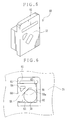
- the shaft pad member 50 includes a body 51 of a plate shape which has a front surface 52 and a rear surface 53, and includes an A-shaped projection 55 formed on the rear surface 53.
- the projection 55 is inserted in the first support holes 34 and 35 of the rear plate 33.
- the rear surface 53 partially contacts the end surfaces 46 and 47 of the guide shafts 25 and 26.
- a link portion 65 extends diagonally for linking the "inverted V" in the A-shape.
- One surface of the link portion 65 is a pressure surface 56 for pressing an outer surface of the rear ends 44 and 45 of the guide shafts 25 and 26.
- the shaft pad member 50 is formed from a plastic material with resiliency.
- a plastic material with resiliency For example, urethane, nylon, polyacetal and the like are preferable with suitable rigidity and suitable resiliency.
- the lens housing 20 is formed from aluminum or hard plastic material.
- the guide shafts 25 and 26 are formed from metal.
- the first support hole 34 includes a channel portion 61 and a quadrilateral through hole 62.
- the channel portion 61 is engaged with an edge of the body 51 of the shaft pad member 50.
- the projection 55 is inserted in the through hole 62.
- the projection 55 is press-fitted in a clearance space between the two side lines 63 and 64 and the guide shaft 25.
- an outer surface of the guide shaft 25 is pressed on the two adjacent side lines 65 and 66 by the pressure surface 56 of the projection 55, and positioned in a predetermined position.
- a peripheral edge of the projection 55 is chamfered to facilitate insertion in the clearance space. Note that this is the situation also with the first support hole 35 and the shaft pad member 50 for engagement therewith.
- an infrared cut filter 69 and an imaging device 70 are disposed as illustrated in Fig. 1 .
- the infrared cut filter 69 is driven by an infrared cut filter loading/unloading device (not shown) secured to the lens housing 20.
- the imaging device 70 is fixed on an aluminum plate 71.
- a circuit board 72 is fixed on a rear surface of the aluminum plate.
- the imaging device 70 is attached to the circuit board 72 by soldering.
- the aluminum plate 71 is fixed on a sensor holder 73 (imaging device retaining member).
- the sensor holder 73 is in a plate shape, overlapped on the rear plate 33 of the lens housing body 20, and fastened together with screws.
- a drop preventing surface 74 is positioned on the sensor holder 73 to cover the shaft pad member 50, and contacts the front surface 52 of the shaft pad member 50. This prevents the shaft pad member 50 from dropping out of the first support holes 34 and 35 and coming away from the rear plate 33 when the lens apparatus 10 is transported individually before the lens apparatus 10 is secured to the body of the surveillance camera.
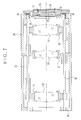
- FIG. 7 a second embodiment of a lens apparatus is illustrated.
- a circuit board 76 is fixed on an aluminum plate 75 (imaging device retaining member).
- the imaging device 70 is fixed on the aluminum plate 75 and also connected with the circuit board 76.
- a sensor cover 77 for covering the imaging device 70 is fixed on the aluminum plate 75.
- the aluminum plate 75 is attached to the rear plate 33 of the lens housing 20 by screws (not shown).
- a drop preventing surface 78 is positioned on the aluminum plate 75 to cover the shaft pad member 50. The drop preventing surface 78 contacts the front surface 52 of the body 55 of the shaft pad member 50 to prevent drop from the first support holes 34 and 35.
- a third embodiment of a lens apparatus is illustrated.
- the imaging device 70 is fixed on an aluminum plate 81.
- the aluminum plate 81 is fixed on a circuit board 82 (imaging device retaining member).
- a sensor cover 83 for covering the imaging device 70 is fixed on the circuit board 82.
- the circuit board 82 is attached to the rear plate 33 of the lens housing 20 by screws (not shown).
- a drop preventing surface 84 is positioned on the circuit board 82 to cover a shaft pad member 80, and contacts a pad portion 85 of the shaft pad member 80 to prevent the shaft pad member 80 from dropping out of the first support holes 34 and 35.
- the shaft pad member 50 described above may be used in place of the shaft pad member 80. It is possible in the first and second embodiments to use the shaft pad member 80 in turn.
- the shaft pad member 80 has the pad portion 85 for contacting the drop preventing surface 84.
- the pad portion 85 is a plate portion (extension) formed by bending back one end of a body 86 in a U shape, and pressed by the drop preventing surface 84.
- a plurality of circular bosses 88 with a small spherical surface are formed on a flat surface of the pad portion 85, and contact the drop preventing surface 84.
- the pad portion 85 is resiliently deformed at a curved portion in a U shape when pushed by the drop preventing surface 84, absorbs surplus force of push from the drop preventing surface 84, and prevents unwanted force from exertion to the circuit board 82 and the guide shafts 25 and 26.
- the front and rear plates are formed together with the housing body in the above-described lens housing, the front and rear plates may be attached to the housing body.
- the lens apparatus of the present invention can be used for a broadcast camera, recording camera for recording vehicle accidents, and the like in addition to the surveillance camera described above.
Landscapes
- Physics & Mathematics (AREA)
- General Physics & Mathematics (AREA)
- Optics & Photonics (AREA)
- Lens Barrels (AREA)
- Accessories Of Cameras (AREA)
- Studio Devices (AREA)
Applications Claiming Priority (2)
| Application Number | Priority Date | Filing Date | Title |
|---|---|---|---|
| JP2011065329 | 2011-03-24 | ||
| PCT/JP2012/057011 WO2012128248A1 (fr) | 2011-03-24 | 2012-03-19 | Dispositif à objectif |
Publications (2)
| Publication Number | Publication Date |
|---|---|
| EP2690476A1 true EP2690476A1 (fr) | 2014-01-29 |
| EP2690476A4 EP2690476A4 (fr) | 2014-11-05 |
Family
ID=46879395
Family Applications (1)
| Application Number | Title | Priority Date | Filing Date |
|---|---|---|---|
| EP12761516.9A Withdrawn EP2690476A4 (fr) | 2011-03-24 | 2012-03-19 | Dispositif à objectif |
Country Status (5)
| Country | Link |
|---|---|
| US (1) | US20140022654A1 (fr) |
| EP (1) | EP2690476A4 (fr) |
| JP (1) | JPWO2012128248A1 (fr) |
| CN (1) | CN103443684A (fr) |
| WO (1) | WO2012128248A1 (fr) |
Families Citing this family (6)
| Publication number | Priority date | Publication date | Assignee | Title |
|---|---|---|---|---|
| CN103713370B (zh) * | 2012-10-09 | 2015-11-11 | 南京理工大学 | 一种使用三坐标测量仪装调近红外大型长焦距镜头的方法 |
| JP5962545B2 (ja) * | 2013-03-06 | 2016-08-03 | コニカミノルタ株式会社 | レンズ鏡筒及び撮像装置 |
| KR102527790B1 (ko) * | 2018-01-30 | 2023-04-28 | 엘지이노텍 주식회사 | 카메라 모듈 |
| CN112540441B (zh) * | 2019-09-06 | 2025-05-27 | 新思考电机有限公司 | 透镜驱动装置、照相机装置以及电子设备 |
| JP7183135B2 (ja) * | 2019-10-24 | 2022-12-05 | 新思考電機有限公司 | レンズ駆動装置、カメラ装置及び電子機器 |
| CN111123461B (zh) * | 2020-01-10 | 2025-03-21 | 中山联合光电科技股份有限公司 | 一种光学镜头结构 |
Family Cites Families (9)
| Publication number | Priority date | Publication date | Assignee | Title |
|---|---|---|---|---|
| JP2000266982A (ja) * | 1999-03-15 | 2000-09-29 | Sony Corp | レンズ鏡筒 |
| US7061699B2 (en) * | 2002-03-28 | 2006-06-13 | Seiko Epson Corporation | Projection lens, producing method of projection lens and projector having projection lens |
| JP4487531B2 (ja) * | 2003-10-02 | 2010-06-23 | ソニー株式会社 | レンズ鏡筒 |
| JP2005257784A (ja) * | 2004-03-09 | 2005-09-22 | Olympus Corp | カメラ及びレンズ装置及び携帯型情報機器 |
| JP2006163006A (ja) * | 2004-12-08 | 2006-06-22 | Nec Access Technica Ltd | カメラモジュール固定構造及びその固定方法並びにそれを用いた携帯端末 |
| US7848638B2 (en) * | 2005-10-11 | 2010-12-07 | Fujiflim Corporation | Lens assembly, lens moving device and assembling method |
| JP2007178779A (ja) * | 2005-12-28 | 2007-07-12 | Seiko Instruments Inc | レンズ移動装置及びカメラモジュール |
| CN201096944Y (zh) * | 2007-08-21 | 2008-08-06 | 三星高新电机(天津)有限公司 | 支撑定位无调焦的手机摄像头 |
| JP4896102B2 (ja) * | 2008-09-12 | 2012-03-14 | 富士フイルム株式会社 | レンズ装置 |
-
2012
- 2012-03-19 EP EP12761516.9A patent/EP2690476A4/fr not_active Withdrawn
- 2012-03-19 CN CN2012800146750A patent/CN103443684A/zh active Pending
- 2012-03-19 WO PCT/JP2012/057011 patent/WO2012128248A1/fr not_active Ceased
- 2012-03-19 JP JP2013505964A patent/JPWO2012128248A1/ja not_active Abandoned
-
2013
- 2013-09-20 US US14/032,843 patent/US20140022654A1/en not_active Abandoned
Non-Patent Citations (2)
| Title |
|---|
| No further relevant documents disclosed * |
| See also references of WO2012128248A1 * |
Also Published As
| Publication number | Publication date |
|---|---|
| EP2690476A4 (fr) | 2014-11-05 |
| CN103443684A (zh) | 2013-12-11 |
| US20140022654A1 (en) | 2014-01-23 |
| JPWO2012128248A1 (ja) | 2014-07-24 |
| WO2012128248A1 (fr) | 2012-09-27 |
Similar Documents
| Publication | Publication Date | Title |
|---|---|---|
| EP2690476A1 (fr) | Dispositif à objectif | |
| CN101246245B (zh) | 驱动装置、透镜镜筒以及照相机 | |
| US7733577B2 (en) | Lens barrel | |
| JP4896102B2 (ja) | レンズ装置 | |
| US7515360B2 (en) | Lens barrel and lens barrel system | |
| EP2481633A1 (fr) | Phare de véhicule | |
| JP6788354B2 (ja) | レンズアクセサリ、レンズ装置、および、撮像装置 | |
| US8570665B2 (en) | Lens barrel having cam cylinder with cam groove | |
| EP1484626A1 (fr) | Mécanisme pour déplacer un objet à l'aide d'une vis sans fin | |
| JP2007226077A (ja) | ズームレンズユニットおよび撮像装置 | |
| EP4270973A3 (fr) | Système optique pour caméra, et dispositif électronique comprenant ledit système optique | |
| US6466379B2 (en) | Lens barrel | |
| US20090185299A1 (en) | Lens driving device | |
| EP2479597A2 (fr) | Barillet de lentille, appareil d'imagerie et dispositif électronique utilisant le barillet de lentille | |
| JP4343569B2 (ja) | レンズ鏡筒 | |
| US9160909B2 (en) | Back focus adjusting module and camera with the back focus adjusting module | |
| EP2481634A1 (fr) | Phare de véhicule | |
| US7474845B2 (en) | Lens barrel with a releasable engagement | |
| US9151926B2 (en) | Adjustable lens mount for a strip lens | |
| KR101624653B1 (ko) | 렌즈 구동 장치 | |
| JP2006113308A (ja) | レンズ駆動装置および撮像装置 | |
| JP2021124710A (ja) | レンズ鏡筒及び撮像装置 | |
| US8649116B2 (en) | Lens barrel and imaging optical system | |
| KR102930719B1 (ko) | 렌즈 구동장치, 카메라 모듈 및 카메라 탑재 장치 | |
| EP1998203A1 (fr) | Barillet de lentille et caméra |
Legal Events
| Date | Code | Title | Description |
|---|---|---|---|
| PUAI | Public reference made under article 153(3) epc to a published international application that has entered the european phase |
Free format text: ORIGINAL CODE: 0009012 |
|
| 17P | Request for examination filed |
Effective date: 20130920 |
|
| AK | Designated contracting states |
Kind code of ref document: A1 Designated state(s): AL AT BE BG CH CY CZ DE DK EE ES FI FR GB GR HR HU IE IS IT LI LT LU LV MC MK MT NL NO PL PT RO RS SE SI SK SM TR |
|
| DAX | Request for extension of the european patent (deleted) | ||
| RIC1 | Information provided on ipc code assigned before grant |
Ipc: G02B 7/10 20060101ALI20140911BHEP Ipc: G02B 7/02 20060101AFI20140911BHEP |
|
| RIC1 | Information provided on ipc code assigned before grant |
Ipc: G02B 7/10 20060101ALI20140926BHEP Ipc: G02B 7/02 20060101AFI20140926BHEP |
|
| A4 | Supplementary search report drawn up and despatched |
Effective date: 20141007 |
|
| RIC1 | Information provided on ipc code assigned before grant |
Ipc: G02B 7/10 20060101ALI20140930BHEP Ipc: G02B 7/02 20060101AFI20140930BHEP |
|
| STAA | Information on the status of an ep patent application or granted ep patent |
Free format text: STATUS: THE APPLICATION IS DEEMED TO BE WITHDRAWN |
|
| 18D | Application deemed to be withdrawn |
Effective date: 20150505 |