EP2691002B1 - Aspirateur - Google Patents
Aspirateur Download PDFInfo
- Publication number
- EP2691002B1 EP2691002B1 EP12711628.3A EP12711628A EP2691002B1 EP 2691002 B1 EP2691002 B1 EP 2691002B1 EP 12711628 A EP12711628 A EP 12711628A EP 2691002 B1 EP2691002 B1 EP 2691002B1
- Authority
- EP
- European Patent Office
- Prior art keywords
- vacuum cleaner
- accordance
- external air
- closing body
- force
- Prior art date
- Legal status (The legal status is an assumption and is not a legal conclusion. Google has not performed a legal analysis and makes no representation as to the accuracy of the status listed.)
- Active
Links
Images

Classifications
-
- A—HUMAN NECESSITIES
- A47—FURNITURE; DOMESTIC ARTICLES OR APPLIANCES; COFFEE MILLS; SPICE MILLS; SUCTION CLEANERS IN GENERAL
- A47L—DOMESTIC WASHING OR CLEANING; SUCTION CLEANERS IN GENERAL
- A47L5/00—Structural features of suction cleaners
- A47L5/12—Structural features of suction cleaners with power-driven air-pumps or air-compressors, e.g. driven by motor vehicle engine vacuum
- A47L5/22—Structural features of suction cleaners with power-driven air-pumps or air-compressors, e.g. driven by motor vehicle engine vacuum with rotary fans
- A47L5/36—Suction cleaners with hose between nozzle and casing; Suction cleaners for fixing on staircases; Suction cleaners for carrying on the back
- A47L5/365—Suction cleaners with hose between nozzle and casing; Suction cleaners for fixing on staircases; Suction cleaners for carrying on the back of the vertical type, e.g. tank or bucket type
-
- A—HUMAN NECESSITIES
- A47—FURNITURE; DOMESTIC ARTICLES OR APPLIANCES; COFFEE MILLS; SPICE MILLS; SUCTION CLEANERS IN GENERAL
- A47L—DOMESTIC WASHING OR CLEANING; SUCTION CLEANERS IN GENERAL
- A47L9/00—Details or accessories of suction cleaners, e.g. mechanical means for controlling the suction or for effecting pulsating action; Storing devices specially adapted to suction cleaners or parts thereof; Carrying-vehicles specially adapted for suction cleaners
- A47L9/20—Means for cleaning filters
Definitions
- the invention relates to a vacuum cleaner with a dirt collecting container, which has a suction inlet and is connected via a filter and a suction with a suction unit in flow connection, and with a discharging into the suction outside air inlet, which is closed by an external air valve, wherein the external air valve comprises a closing body, which can be acted upon by a retaining force in a closing position closing at least one retaining element in a closed position closing the outside air inlet and being movable against the action of the retaining force from the closed position into a release position releasing the outside air inlet.
- the vacuum cleaner By means of the vacuum cleaner in question, dirt and preferably also liquid from a surface to be cleaned, in particular a bottom surface, can be sucked into a dirt collecting container, which can be subjected to negative pressure by a suction unit, so that a suction flow is formed.
- the vacuum cleaner has at least one filter which is arranged in the flow path from the dirt collecting container to the suction unit and serves to separate solids from the suction flow.
- dirt particles increasingly accumulate on the side of the filter facing the dirt collecting container, so that the filter has to be cleaned after some time.
- the side of the filter facing away from the dirt collecting container can be charged with external air, which can flow into the suction line via a forced air inlet.
- the external air intake is during the normal suction operation of the vacuum cleaner from the closing body of a forced air valve locked.
- the closing body assumes a closed position in which it is subjected to a holding force by at least one holding element.
- the external air valve is opened by moving the closing body into a release position, in which it releases the outside air inlet.
- External air can then flow into the suction line via the external air inlet and act on the side of the filter facing away from the dirt collector. At least part of the external air can flow through the filter in the counterflow direction, ie against the flow direction which forms during the normal suction operation. Dirt particles, which adhere to the dirt collecting container side facing the filter, are thereby released from the filter.
- the forced air inlet can then be closed again, so that the normal suction operation can be continued.
- the negative pressure increases to such an extent that the force load resulting from the pressure difference can no longer be completely compensated by the permanent magnet and the closing spring and therefore the hood moves into its release position against the action of the closing spring.
- the filter is then flowed through in countercurrent direction by the external air, so that adhering to the filter Remove dirt particles.
- the inflowing external air causes a pressure equalization on the displaceable hood, so that the initially acting pressure difference is eliminated and the hood is again transferred to its closed position under the action of the closing spring.
- the suction operation can then be continued.
- a vacuum cleaner is known with a dirt collecting container having a suction inlet and is connected via a filter and a suction line with a suction unit in flow communication.
- a forced air inlet which can be closed by an external air valve.
- the external air valve has a closing body which can be acted upon by a closing force in a closed position closing the outside air inlet.
- the closing force results from the pressure difference between the negative pressure prevailing during the suction operation in the dirt collecting container and the atmospheric pressure prevailing outside the dirt collecting container.
- the closing body projects laterally beyond the outside air inlet.
- this lateral region is located on the closing body to a coil spring, which can be stretched by the user and in this case exerts a release force on the closing body. If the release force of the helical spring exceeds the closing force resulting from the pressure difference, then the closing body moves from its closed position into an open position, in which it releases the outside air inlet, and the helical spring relaxes.
- Object of the present invention is to provide a vacuum cleaner of the generic type having an improved filter cleaning.
- the filter cleaning can be enhanced by ensuring that the external air can act impulsively on the side facing away from the dirt collecting container of the filter.
- the vacuum cleaner according to the invention on an external air valve with at least one holding element that abruptly changes its shape when exposed to a certain release force and thereby releases the closing body, so that it can move from its closed position to its release position within a very short time.
- the release force is the holding force, which is exerted in the closed position of the closing body of the at least one holding element on the closing body, in the opposite direction.
- Exceeds the release force a certain value, which can be specified by the manufacturer, the at least one holding element abruptly changes its shape and thereby releases the closing body.
- the at least one retaining element is designed as a cantilevered support arm, which engages under the closing body.
- the support arm In the closed position of the closing body, the support arm may have a rectilinear shape and act on the closing body with a holding force, so that the closing body reliably maintains its closed position. If the support arm is acted upon by a certain release force, it abruptly changes its shape, for example, in such a way that it kinks and thereby releases the closing body.
- the support arm has a first and a second end. At its first end, it is fixedly fixed to a component of the vacuum cleaner, whereas the second end is not fixed.
- the closing body can preferably rest flat on the support arm until the support arm is subjected to a certain release force and the support arm thereby abruptly assumes its second, mechanically unstable form.
- the transition between the first and the second form of the support arm can be done within a very short time, so that the closing body within a very short time its release position take and external air impulsively beaufschline the filter to be cleaned.
- the at least one retaining element is prestressed in the direction of the closed position of the closing body. As a result, a reliable sealing of the outside air inlet can be ensured in a structurally simple manner when the closing body assumes its closed position.
- the at least one retaining element automatically assumes its first, mechanically stable form when the release force ceases.
- the at least one retaining element assumes its first, mechanically stable form in the closed position of the closing body. If the retaining element is subjected to a specific holding force, it abruptly changes its shape and changes into a second, mechanically unstable shape. If the release force is omitted, the at least one retaining element in the preferred embodiment of the invention automatically performs a renewed change in shape and reverts to its first, mechanically stable form. An actuator for returning the retaining element from the second mold into the first mold can thereby be dispensed with.
- the support arm is channel-shaped.
- the trough-shaped configuration can be ensured in a structurally simple manner that the support arm abruptly changes its shape when exposed to a certain release force.
- the support arm is made of a flat material, in particular of a steel sheet, for example of spring steel.
- a strip-shaped configuration of the support arm has proved to be advantageous.
- the support arm is designed as a curved steel strip.
- the steel strip can be clamped on one side between two clamping jaws and aligned in the unloaded state in a straight line. Transversely to its longitudinal direction, the steel strip may have a curved, channel-like configuration. If the steel strip is acted upon by a certain release force, it kinks abruptly with its free end region and assumes a second, mechanically unstable form.
- the external air valve has at least two identical holding elements. It can be provided, for example, that the external air valve has two support arms, which are each formed as a curved steel strip.
- the at least one holding element automatically stops when the release force is removed, starting from its second, mechanically unstable form in its first, mechanically stable form passes. In this transition, it can move the closing body in its closed position.
- the external air valve has a restoring device, which acts on the closing body in the release position with a restoring force. The restoring force is aligned in the direction of the closed position of the closing body and ensures that the closing body reliably assumes its closed position in the absence of the release force.
- the restoring device and the at least one retaining element are designed as separate components in an advantageous embodiment of the invention.
- the at least one retaining element is mechanically decoupled from the restoring device in its second, mechanically unstable form.
- the return device moves the closing body of the external air valve independently of the at least one retaining element in its closed position.
- the retaining element is not acted upon by the restoring device with a restoring force but only the closing body.
- the movement of the closing body caused by the restoring device in the closed position releases the at least one holding element, so that this is not subject to mechanical loading by the closing body and can automatically move from its second, mechanically unstable form into its first, mechanically stable form.
- the restoring device has, in an advantageous embodiment of the invention, at least one spring element.
- the closing body of the external air valve is subject to a pressure difference during the normal suction operation of the vacuum cleaner, which results from the fact that the closing body is acted upon on the one hand by the atmospheric pressure prevailing outside the vacuum cleaner and on the other hand by the vacuum prevailing in the suction line. So that the closing body despite This pressure difference during normal suction operation maintains its closed position, it is acted upon by the at least one holding element with a holding force. So that the at least one retaining element for filter cleaning passes into its second, mechanically unstable form, the negative pressure prevailing in the suction line can be increased. The pressure increase then leads to a release force directed counter to the holding force, under the effect of which the at least one retaining element abruptly changes its shape.
- the increased negative pressure can be done, for example, by closing a suction line connected to the suction inlet.
- the external air valve has an actuating member for acting on the at least one holding element with the release force.
- the actuator can cooperate with a drive element that can be activated by the user. It can also be provided that the drive element cooperates with a control device of the vacuum cleaner and is activated by the latter automatically, for example, as a function of time and / or as a function of certain operating conditions of the vacuum cleaner.
- the external air valve is manually actuated. This gives the user the opportunity to perform a filter cleaning if he considers it necessary. For this purpose, the user can move the closing body of the external air valve into its release position.
- the actuator of the external air valve has a plunger which is connected to the closing body and engages through a housing of the vacuum cleaner.
- a release force on the Closing bodies are exercised, so that the at least one holding element abruptly changes its shape and releases the closing body.
- the plunger is conveniently movable in the vertical direction. In a manual operation of the plunger, it has proved to be advantageous if the user can move the plunger in the vertical direction from top to bottom. This facilitates the handling of the vacuum cleaner and allows a particularly fast opening movement of the closing body from its closed position to its release position. As a result, a particularly effective cleaning of the filter can be achieved.
- the plunger carries at its end protruding from the housing a handle and is surrounded by a return spring which is supported on the one hand on the housing and on the other hand on the handle.
- the handle may be plate-shaped and conveniently moved by the user in the vertical direction.
- a return spring can be clamped, which acts on the closing body on the handle and the plunger with a restoring force when the user releases the handle. Under the action of the restoring force then the closing body goes over after the filter cleaning in its closed position.
- the closing body is preferably designed as a valve flap, which is pivotable about a pivot axis.
- the valve flap with the interposition of a sealing element on the edge of the outside air inlet.
- a positioning of the valve flap within the suction line is advantageous because this makes it possible to swing the valve flap to release the forced air inlet in the suction line by the user presses the pivot axis remote from the region of the valve flap in the vertical direction downwards.
- valve flap is connected in an articulated manner to an actuating element which passes through the outside air inlet and manually movable in the vertical direction.
- the actuator may be formed as a plunger, which protrudes beyond the outside air inlet from the housing of the vacuum cleaner and carries at its free end a handle.
- a vacuum cleaner 10 is shown schematically with a dirt collecting container 12, on which a suction head 14 is placed.
- the dirt collecting container 12 has a suction inlet 16, to which in the usual way a suction line, in the illustrated embodiment, a suction hose 18, can be connected.
- the suction head 14 seals the dirt collecting container 12 on the upper side and forms a suction outlet 20, on which a filter 22 is held.
- the filter 22 is followed in the suction head by a suction line 24, via which the dirt collecting container 12 is in fluid communication with a suction unit arranged in the suction unit 26.
- the suction unit 26 comprises an electric motor 28 and a fan 30 driven by the electric motor 28.
- the dirt collecting 12 can be acted upon by the suction unit 26 with negative pressure, so that a in FIG. 1 formed by the arrows 32 shown Saugströmung.
- suction air can be sucked through the suction hose 18 and the suction inlet 16 into the dirt collecting 12, which is then sucked by the suction unit 26.
- the suction air can be discharged from the suction unit 26 via slot-shaped exhaust air openings 34 to the environment.
- the exhaust ports 34 are formed in a housing 36 of the suction head 12.
- the suction air flows through the filter 22, so that entrained dirt particles deposit on the dirt collecting container 12 facing dirty side 38 of the filter 22. It is therefore necessary to clean the filter 22 from time to time, since otherwise it forms an increasing flow resistance and the suction effect of the vacuum cleaner 10 is impaired.
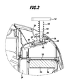
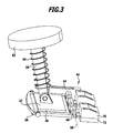
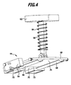
- the suction line 24 above the filter 22 on a forced air inlet 40 in which an annular sealing insert 42 is inserted and the one of the in the Figures 3 and 4 Enlarged illustrated external air valve 44 can be closed.
- the external air valve 44 includes a closing body in the form of a valve flap 46, which is pivotable about a predetermined by the longitudinal axis of the bearing pin 48 pivot axis 50 between a closed position shown in the drawing by means of a bearing pin 48, in which they sealing with their side facing away from the filter 22 top 52 on the sealing insert 42 abuts, and a release position, not shown in the drawing, in which it releases the sealing insert 42 and thus also the outside air inlet 40 and projects into the suction line 24.
- a closing body in the form of a valve flap 46, which is pivotable about a predetermined by the longitudinal axis of the bearing pin 48 pivot axis 50 between a closed position shown in the drawing by means of a bearing pin 48, in which they sealing with their side facing away from the filter 22 top 52 on the sealing insert 42 abuts, and a release position, not shown in the drawing, in which it releases the sealing insert 42 and thus also the outside air inlet 40 and projects into the suction line 24.
- the bearing pin 48 is each end held on a bearing body 54 which is fixed to a wall 56 of the suction line 24. In the drawing, only a bearing body 54 is shown for clarity.
- the wall 56 of the suction line 24 has the outside air inlet 40.
- a plunger 58 is articulated, which forms an actuator of the external air valve 44 and passes through both the outside air inlet 40 and above the outside air inlet 40 arranged opening 60 of the housing 36 of the suction head 14.
- the plunger 58 protrudes in a vertical direction out of the housing 30 and carries at its free end facing away from the valve flap 56 a plate-shaped handle 62.
- a restoring device in the form of a helical return spring 64 , which is supported on the one hand on the housing 36 and on the other hand on the handle 62.
- valve flap 46 is supported in its closed position by two identically designed holding elements in the form of two support arms 66, 68, which act on the valve flap 46 with the outside air inlet 40 and the sealing insert 42 facing holding force.
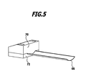
- the two support arms 66, 68 are each configured as a channel-shaped curved steel strip, which is clamped on one side between an upper jaw 70 and a lower jaw 72.
- the two clamping jaws 70 and 72 are fixed to the wall 56 of the suction line 24.
- the one-sided determination of the channel-shaped, made of a spring steel sheet support arms makes it possible to bias them in the direction of the filter 22 facing bottom 74 of the valve flap 46, so that during the normal suction operation of the vacuum cleaner 10 despite the force acting on the valve flap 46 pressure difference reliably is held in its closed position.
- the pressure difference therefore results that the top 52 of the valve flap 46 in the region of the outside air inlet 40 with the outside the vacuum prevailing atmospheric pressure is applied, whereas the bottom 74 of the valve flap 46 is acted upon in the region of the outside air inlet 40 with the forming during the suction operation in the suction line 24 negative pressure.
- valve flap 46 In addition to the holding force exerted by the two support arms 66, 68 on the valve flap 46, the valve flap 46 is still acted upon by the spring force of the return spring 64, which is directed in the same direction as the holding force exerted by the support arms 66, 68 , However, the spring force is only a fraction of the holding force.
- the user wants to clean the filter 22, he can push the plunger 58 by means of the handle 62 against the spring force of the return spring 64 and against the holding force of the two support arms 66, 68 vertically downwards. The user exerts thereby via the plunger 58 a release force on the valve flap 46. If the release force exceeds a predefinable value, then the two support arms 66, 68 abruptly bend downwards in the direction away from the valve flap 46 and thereby release the valve flap 46. Starting from their particular in the FIGS.
- valve flap 46 then moves within a very short time from its closed position into its release position, so that external air can flow into the suction line 24 via the outside air inlet 40 and the clean side 76 of the filter 22 facing away from the dirt collecting container 12 can act like a pulse.
- the pulse-like application leads to a mechanical vibration of the filter 22, so that detached on the dirty side 38 adhering dirt particles.
- the cleaning is further enhanced by a portion of the inflowing external air, the filter 22 in the counterflow direction, that flows through against the suction flow 32.
- the user can release the handle 62 again.
- the associated omission of the release force causes the valve flap 46 moves automatically under the action of the spring force exerted by the return spring 64 in its closed position.
- the support arms 66, 68 then hold the valve flap 64 reliably in its closed position, so that the normal suction operation of the vacuum cleaner 10 can be continued.
- the sudden transition of the support arms 66, 68 of their first, mechanically stable form in their second, mechanically unstable shape allows a particularly effective cleaning of the filter 22, as this can be applied within a very short time with external air.
- the sudden change in shape takes place only when the user acts on the valve flap 46 with a predetermined release force. If the release force reaches a certain value, then due to the abrupt change in shape of the support arms 66, 68, the holding force exerted by these on the valve flap 46 and the valve flap 46 are transferred to their release position within a very short time. The user must thus exceed for cleaning the filter a by the design of the support arms 66, 68 predeterminable threshold. As long as the threshold has not yet been reached, the valve flap 46 remains virtually motionless in its closed position, the threshold is exceeded, the valve flap 46 is abruptly in its release position.
- a filter cleaning is triggered by pressing the plunger 58.
- the user closes the suction hose 18 to trigger a filter cleaning, so that an increased negative pressure is established in the suction line 24. If the negative pressure reaches a predetermined value, then the support arms 66, 68 suddenly change over to their second, mechanically unstable form and release the valve flap 46, which then releases into its release position within a very short time passes. Again, a gradual movement of the valve flap 46 is inhibited, but a movement of the valve flap 46 takes place only when a predetermined threshold is exceeded.
Landscapes
- Engineering & Computer Science (AREA)
- Mechanical Engineering (AREA)
- Filters For Electric Vacuum Cleaners (AREA)
- Filtering Of Dispersed Particles In Gases (AREA)
Claims (18)
- Aspirateur (10) pourvu d'un contenant collecteur de poussière (12) qui comprend une entrée d'aspiration (16) et qui est en communication fluidique avec une unité d'aspiration (26) par l'intermédiaire d'un filtre (22) et d'une conduite d'aspiration (24), et pourvu d'une entrée d'air extérieur (40) débouchant dans la conduite d'aspiration (24) et pouvant être fermée par une soupape d'air extérieur (44), la soupape d'air extérieur (44) comprenant un corps de fermeture (46) pouvant être soumis à l'effet d'une force de retenue, dans une position fermée fermant l'entrée d'air extérieur (40), par au moins un élément de retenue (66, 68) et pouvant être déplacé à l'encontre de l'effet de la force de retenue de la position fermée dans une position libérée libérant l'entrée d'air extérieur, l'élément ou les éléments de retenue (66, 68), lorsqu'ils sont soumis à l'effet d'une force de libération définie, passant brusquement d'une première forme mécaniquement stable, dans laquelle ils soumettent le corps de fermeture (46) à l'effet de la force de retenue, à une seconde forme mécaniquement instable, dans laquelle ils libèrent le corps de fermeture (46), caractérisé en ce qu'au moins un élément de retenue est réalisé sous la forme d'un bras de support (66, 68) fixé unilatéralement qui vient se plaquer sous le corps de fermeture (46).
- Aspirateur selon la revendication 1, caractérisé en ce que le ou les éléments de retenue (66, 68) sont précontraints en direction de la position fermée du corps de fermeture (46).
- Aspirateur selon la revendication 1 ou 2, caractérisé en ce que le ou les éléments de retenue (66, 68), à la disparition de la force de libération, adoptent automatiquement leur première forme mécaniquement stable.
- Aspirateur selon l'une quelconque des revendications précédentes, caractérisé en ce que le bras de support (66, 68) est réalisé sous la forme d'une goulotte.
- Aspirateur selon l'une quelconque des revendications précédentes, caractérisé en ce que le bras de support (66, 68) est fabriqué à partir d'un matériau plat.
- Aspirateur selon l'une quelconque des revendications précédentes, caractérisé en ce que le bras de support (66, 68) est réalisé sous la forme d'un ruban d'acier courbé.
- Aspirateur selon l'une quelconque des revendications précédentes, caractérisé en ce que la soupape d'air extérieur (44) comprend au moins deux éléments de retenue (66, 68) identiques.
- Aspirateur selon l'une quelconque des revendications précédentes, caractérisé en ce que la soupape d'air extérieur (44) comprend un dispositif de rappel (64) soumettant le corps de fermeture (46), dans la position libérée, à une force de rappel.
- Aspirateur selon la revendication 8, caractérisé en ce que le dispositif de rappel (64) et le ou les éléments de retenue (66, 68) sont réalisés sous la forme d'éléments séparés.
- Aspirateur selon la revendication 8 ou 9, caractérisé en ce que le ou les éléments de retenue (66, 68), dans leur seconde forme mécaniquement instable, sont découplés mécaniquement du dispositif de rappel (64).
- Aspirateur selon l'une quelconque des revendications 8 à 10, caractérisé en ce que le dispositif de rappel comprend un élément ressort (64).
- Aspirateur selon l'une quelconque des revendications précédentes, caractérisé en ce que la soupape d'air extérieur (44) comprend un organe d'actionnement (58) permettant de soumettre le ou les éléments de retenue (66, 68) à la force de libération.
- Aspirateur selon la revendication 12, caractérisé en ce que la soupape d'air extérieur (44) peut être actionnée manuellement.
- Aspirateur selon la revendication 12 ou 13, caractérisé en ce que l'organe d'actionnement comprend un poussoir (58) qui est relié au corps de fermeture (46) et traverse un boîtier (36) de l'aspirateur (10).
- Aspirateur selon la revendication 14, caractérisé en ce que le poussoir (58) peut être déplacé dans la direction verticale.
- Aspirateur selon la revendication 14 ou 15, caractérisé en ce que le poussoir (58) porte à son extrémité faisant saillie du boîtier (36) une poignée (62) et est entouré par un ressort de rappel (64) qui s'appuie d'une part sur le boîtier (36) et d'autre part sur la poignée (62).
- Aspirateur selon l'une quelconque des revendications précédentes, caractérisé en ce que le corps de fermeture est réalisé sous la forme d'un clapet de soupape (46) qui peut pivoter autour d'un axe de pivotement (50).
- Aspirateur selon la revendication 17, caractérisé en ce que le clapet de soupape (46) est relié de manière articulée à un organe d'actionnement (58) qui traverse l'entrée d'air extérieur (40) et peut être déplacé manuellement dans la direction verticale.
Applications Claiming Priority (2)
| Application Number | Priority Date | Filing Date | Title |
|---|---|---|---|
| DE102011006361A DE102011006361A1 (de) | 2011-03-29 | 2011-03-29 | Staubsauger |
| PCT/EP2012/055340 WO2012130806A1 (fr) | 2011-03-29 | 2012-03-26 | Aspirateur |
Publications (2)
| Publication Number | Publication Date |
|---|---|
| EP2691002A1 EP2691002A1 (fr) | 2014-02-05 |
| EP2691002B1 true EP2691002B1 (fr) | 2015-10-28 |
Family
ID=45926555
Family Applications (1)
| Application Number | Title | Priority Date | Filing Date |
|---|---|---|---|
| EP12711628.3A Active EP2691002B1 (fr) | 2011-03-29 | 2012-03-26 | Aspirateur |
Country Status (4)
| Country | Link |
|---|---|
| EP (1) | EP2691002B1 (fr) |
| CN (1) | CN103458752B (fr) |
| DE (1) | DE102011006361A1 (fr) |
| WO (1) | WO2012130806A1 (fr) |
Families Citing this family (9)
| Publication number | Priority date | Publication date | Assignee | Title |
|---|---|---|---|---|
| CN103767623B (zh) * | 2014-02-28 | 2016-04-13 | 天佑电器(苏州)有限公司 | 具有自清洁功能的吸尘器 |
| DK178434B1 (en) | 2015-01-02 | 2016-02-22 | Producteers As | Automatic Filter Cleaning System |
| DE102015113189A1 (de) * | 2015-08-11 | 2017-02-16 | Festool Gmbh | Sauggerät |
| DE102016100780A1 (de) | 2016-01-19 | 2017-07-20 | Festool Gmbh | Sauggerät |
| DE102016100820B4 (de) * | 2016-01-19 | 2025-01-23 | Vorwerk & Co. Interholding Gmbh | Saugreinigungsgerät |
| CN108652516B (zh) * | 2018-07-21 | 2023-12-29 | 苏州欧圣电气股份有限公司 | 吸尘器 |
| CN113729556A (zh) * | 2020-05-29 | 2021-12-03 | 天佑电器(苏州)有限公司 | 清洁吸尘设备的过滤器的方法及吸尘设备 |
| WO2022109107A1 (fr) | 2020-11-19 | 2022-05-27 | Milwaukee Electric Tool Corporation | Dépoussiéreur portatif |
| CN116919257A (zh) * | 2022-04-08 | 2023-10-24 | 北京石头世纪科技股份有限公司 | 清洁机器人 |
Family Cites Families (4)
| Publication number | Priority date | Publication date | Assignee | Title |
|---|---|---|---|---|
| DE29823411U1 (de) | 1998-05-08 | 1999-05-20 | Alfred Kärcher GmbH & Co, 71364 Winnenden | Sauggerät für Reinigungszwecke |
| DK2046182T3 (da) * | 2006-07-29 | 2014-08-18 | Kaercher Gmbh & Co Kg Alfred | Støvsuger med selvrensende filterindretning |
| DE102008031544A1 (de) * | 2008-07-07 | 2010-01-21 | Dichtungstechnik G. Bruss Gmbh & Co. Kg | Federzungenventil für eine Ölabscheidevorrichtung für die Kurbelgehäuseentlüftung eines Kraftfahrzeugs |
| WO2011003441A1 (fr) * | 2009-07-07 | 2011-01-13 | Alfred Kärcher Gmbh & Co. Kg | Dispositif d'aspiration à des fins de nettoyage |
-
2011
- 2011-03-29 DE DE102011006361A patent/DE102011006361A1/de not_active Withdrawn
-
2012
- 2012-03-26 EP EP12711628.3A patent/EP2691002B1/fr active Active
- 2012-03-26 WO PCT/EP2012/055340 patent/WO2012130806A1/fr not_active Ceased
- 2012-03-26 CN CN201280016431.6A patent/CN103458752B/zh active Active
Also Published As
| Publication number | Publication date |
|---|---|
| CN103458752B (zh) | 2016-04-13 |
| EP2691002A1 (fr) | 2014-02-05 |
| WO2012130806A1 (fr) | 2012-10-04 |
| DE102011006361A1 (de) | 2012-10-04 |
| CN103458752A (zh) | 2013-12-18 |
Similar Documents
| Publication | Publication Date | Title |
|---|---|---|
| WO2012130806A1 (fr) | Aspirateur | |
| EP2046183B1 (fr) | Procédé pour nettoyer le filtre d'un aspirateur et aspirateur pour mettre en oeuvre le procédé | |
| EP2421630B1 (fr) | Procédé pour décrasser les deux filtres d'un aspirateur à des fins de nettoyage et aspirateur pour mettre en oeuvre le procédé | |
| EP1868479B1 (fr) | Procede pour nettoyer les filtres d'un aspirateur et aspirateur pour executer ce procede | |
| EP2979602B1 (fr) | Filtre a air a retrolavage | |
| EP2575587B1 (fr) | Aspirateur avec nettoyage de filtre par contre-courant | |
| EP2046184B1 (fr) | Procede pour nettoyer le filtre d'un aspirateur et aspirateur pour mettre en oeuvre le procede | |
| EP3562769B1 (fr) | Dispositif d'aspiration | |
| EP2451332B1 (fr) | Dispositif d'aspiration à des fins de nettoyage | |
| DE202011050051U1 (de) | Staubbehälter und Staubsammler mit demselben | |
| EP3334319B1 (fr) | Appareil d'aspiration | |
| WO2022063606A1 (fr) | Dispositif de filtration et procédé de nettoyage y relatif | |
| EP2575585B1 (fr) | Aspirateur à soupape d'air extérieur pour le nettoyage du filtre | |
| EP2732747A2 (fr) | Sac filtrant d'aspirateur, avec fermeture de ressort | |
| DE102015108559A1 (de) | Rückspülbarer Luftfilter | |
| EP3405089B1 (fr) | Aspirateur | |
| EP2835089B1 (fr) | Procédé de fonctionnement d'un aspirateur pour le nettoyage d'un élément de filtre enfermé dans l'aspirateur | |
| EP2025279B1 (fr) | Sac filtrant doté d'une plaque de support | |
| EP2424418A1 (fr) | Appareil de nettoyage par aspiration | |
| EP4216786B1 (fr) | Dispositif de filtre pour un aspirateur et procédé de nettoyage de filtre | |
| DE10252933A1 (de) | Flurförderzeug mit einem Kühler und einem Sieb | |
| DE102019102357B4 (de) | Vorrichtung zur Absperrung oder Steuerung des Durchflusses von schmutzbeladener Luft, Reinigungsgerät und Behältnis zum Abtrennen und/oder Sammeln von Schmutz mit einer solchen Vorrichtung | |
| WO2019011429A1 (fr) | Appareil d'aspiration pourvu d'au moins deux filtres et procédé de fonctionnement d'un appareil d'aspiration | |
| EP1552778B1 (fr) | Dispositif d'urinoir à monter sur un W.C. comprenant un siège et/ou un couvercle | |
| EP4301194B1 (fr) | Unité d'aération pour un aspirateur, procédé d'aération d'un aspirateur, aspirateur et utilisation d'un flux d'air pour nettoyer un filtre de l'aspirateur |
Legal Events
| Date | Code | Title | Description |
|---|---|---|---|
| PUAI | Public reference made under article 153(3) epc to a published international application that has entered the european phase |
Free format text: ORIGINAL CODE: 0009012 |
|
| 17P | Request for examination filed |
Effective date: 20130924 |
|
| AK | Designated contracting states |
Kind code of ref document: A1 Designated state(s): AL AT BE BG CH CY CZ DE DK EE ES FI FR GB GR HR HU IE IS IT LI LT LU LV MC MK MT NL NO PL PT RO RS SE SI SK SM TR |
|
| DAX | Request for extension of the european patent (deleted) | ||
| GRAP | Despatch of communication of intention to grant a patent |
Free format text: ORIGINAL CODE: EPIDOSNIGR1 |
|
| INTG | Intention to grant announced |
Effective date: 20150121 |
|
| GRAP | Despatch of communication of intention to grant a patent |
Free format text: ORIGINAL CODE: EPIDOSNIGR1 |
|
| INTG | Intention to grant announced |
Effective date: 20150617 |
|
| GRAS | Grant fee paid |
Free format text: ORIGINAL CODE: EPIDOSNIGR3 |
|
| GRAA | (expected) grant |
Free format text: ORIGINAL CODE: 0009210 |
|
| AK | Designated contracting states |
Kind code of ref document: B1 Designated state(s): AL AT BE BG CH CY CZ DE DK EE ES FI FR GB GR HR HU IE IS IT LI LT LU LV MC MK MT NL NO PL PT RO RS SE SI SK SM TR |
|
| REG | Reference to a national code |
Ref country code: GB Ref legal event code: FG4D Free format text: NOT ENGLISH |
|
| REG | Reference to a national code |
Ref country code: CH Ref legal event code: EP |
|
| REG | Reference to a national code |
Ref country code: AT Ref legal event code: REF Ref document number: 757452 Country of ref document: AT Kind code of ref document: T Effective date: 20151115 |
|
| REG | Reference to a national code |
Ref country code: IE Ref legal event code: FG4D Free format text: LANGUAGE OF EP DOCUMENT: GERMAN |
|
| REG | Reference to a national code |
Ref country code: DE Ref legal event code: R096 Ref document number: 502012005090 Country of ref document: DE |
|
| REG | Reference to a national code |
Ref country code: FR Ref legal event code: PLFP Year of fee payment: 5 |
|
| REG | Reference to a national code |
Ref country code: LT Ref legal event code: MG4D |
|
| REG | Reference to a national code |
Ref country code: NL Ref legal event code: MP Effective date: 20151028 |
|
| PG25 | Lapsed in a contracting state [announced via postgrant information from national office to epo] |
Ref country code: NO Free format text: LAPSE BECAUSE OF FAILURE TO SUBMIT A TRANSLATION OF THE DESCRIPTION OR TO PAY THE FEE WITHIN THE PRESCRIBED TIME-LIMIT Effective date: 20160128 Ref country code: IT Free format text: LAPSE BECAUSE OF FAILURE TO SUBMIT A TRANSLATION OF THE DESCRIPTION OR TO PAY THE FEE WITHIN THE PRESCRIBED TIME-LIMIT Effective date: 20151028 Ref country code: ES Free format text: LAPSE BECAUSE OF FAILURE TO SUBMIT A TRANSLATION OF THE DESCRIPTION OR TO PAY THE FEE WITHIN THE PRESCRIBED TIME-LIMIT Effective date: 20151028 Ref country code: IS Free format text: LAPSE BECAUSE OF FAILURE TO SUBMIT A TRANSLATION OF THE DESCRIPTION OR TO PAY THE FEE WITHIN THE PRESCRIBED TIME-LIMIT Effective date: 20160228 Ref country code: HR Free format text: LAPSE BECAUSE OF FAILURE TO SUBMIT A TRANSLATION OF THE DESCRIPTION OR TO PAY THE FEE WITHIN THE PRESCRIBED TIME-LIMIT Effective date: 20151028 Ref country code: NL Free format text: LAPSE BECAUSE OF FAILURE TO SUBMIT A TRANSLATION OF THE DESCRIPTION OR TO PAY THE FEE WITHIN THE PRESCRIBED TIME-LIMIT Effective date: 20151028 Ref country code: LT Free format text: LAPSE BECAUSE OF FAILURE TO SUBMIT A TRANSLATION OF THE DESCRIPTION OR TO PAY THE FEE WITHIN THE PRESCRIBED TIME-LIMIT Effective date: 20151028 |
|
| PG25 | Lapsed in a contracting state [announced via postgrant information from national office to epo] |
Ref country code: SE Free format text: LAPSE BECAUSE OF FAILURE TO SUBMIT A TRANSLATION OF THE DESCRIPTION OR TO PAY THE FEE WITHIN THE PRESCRIBED TIME-LIMIT Effective date: 20151028 Ref country code: RS Free format text: LAPSE BECAUSE OF FAILURE TO SUBMIT A TRANSLATION OF THE DESCRIPTION OR TO PAY THE FEE WITHIN THE PRESCRIBED TIME-LIMIT Effective date: 20151028 Ref country code: PT Free format text: LAPSE BECAUSE OF FAILURE TO SUBMIT A TRANSLATION OF THE DESCRIPTION OR TO PAY THE FEE WITHIN THE PRESCRIBED TIME-LIMIT Effective date: 20160229 Ref country code: FI Free format text: LAPSE BECAUSE OF FAILURE TO SUBMIT A TRANSLATION OF THE DESCRIPTION OR TO PAY THE FEE WITHIN THE PRESCRIBED TIME-LIMIT Effective date: 20151028 Ref country code: GR Free format text: LAPSE BECAUSE OF FAILURE TO SUBMIT A TRANSLATION OF THE DESCRIPTION OR TO PAY THE FEE WITHIN THE PRESCRIBED TIME-LIMIT Effective date: 20160129 Ref country code: LV Free format text: LAPSE BECAUSE OF FAILURE TO SUBMIT A TRANSLATION OF THE DESCRIPTION OR TO PAY THE FEE WITHIN THE PRESCRIBED TIME-LIMIT Effective date: 20151028 Ref country code: PL Free format text: LAPSE BECAUSE OF FAILURE TO SUBMIT A TRANSLATION OF THE DESCRIPTION OR TO PAY THE FEE WITHIN THE PRESCRIBED TIME-LIMIT Effective date: 20151028 |
|
| PG25 | Lapsed in a contracting state [announced via postgrant information from national office to epo] |
Ref country code: CZ Free format text: LAPSE BECAUSE OF FAILURE TO SUBMIT A TRANSLATION OF THE DESCRIPTION OR TO PAY THE FEE WITHIN THE PRESCRIBED TIME-LIMIT Effective date: 20151028 |
|
| REG | Reference to a national code |
Ref country code: DE Ref legal event code: R097 Ref document number: 502012005090 Country of ref document: DE |
|
| PG25 | Lapsed in a contracting state [announced via postgrant information from national office to epo] |
Ref country code: DK Free format text: LAPSE BECAUSE OF FAILURE TO SUBMIT A TRANSLATION OF THE DESCRIPTION OR TO PAY THE FEE WITHIN THE PRESCRIBED TIME-LIMIT Effective date: 20151028 Ref country code: SK Free format text: LAPSE BECAUSE OF FAILURE TO SUBMIT A TRANSLATION OF THE DESCRIPTION OR TO PAY THE FEE WITHIN THE PRESCRIBED TIME-LIMIT Effective date: 20151028 Ref country code: SM Free format text: LAPSE BECAUSE OF FAILURE TO SUBMIT A TRANSLATION OF THE DESCRIPTION OR TO PAY THE FEE WITHIN THE PRESCRIBED TIME-LIMIT Effective date: 20151028 Ref country code: EE Free format text: LAPSE BECAUSE OF FAILURE TO SUBMIT A TRANSLATION OF THE DESCRIPTION OR TO PAY THE FEE WITHIN THE PRESCRIBED TIME-LIMIT Effective date: 20151028 Ref country code: BE Free format text: LAPSE BECAUSE OF NON-PAYMENT OF DUE FEES Effective date: 20160331 Ref country code: RO Free format text: LAPSE BECAUSE OF FAILURE TO SUBMIT A TRANSLATION OF THE DESCRIPTION OR TO PAY THE FEE WITHIN THE PRESCRIBED TIME-LIMIT Effective date: 20151028 |
|
| PLBE | No opposition filed within time limit |
Free format text: ORIGINAL CODE: 0009261 |
|
| STAA | Information on the status of an ep patent application or granted ep patent |
Free format text: STATUS: NO OPPOSITION FILED WITHIN TIME LIMIT |
|
| 26N | No opposition filed |
Effective date: 20160729 |
|
| PG25 | Lapsed in a contracting state [announced via postgrant information from national office to epo] |
Ref country code: LU Free format text: LAPSE BECAUSE OF FAILURE TO SUBMIT A TRANSLATION OF THE DESCRIPTION OR TO PAY THE FEE WITHIN THE PRESCRIBED TIME-LIMIT Effective date: 20160326 Ref country code: MC Free format text: LAPSE BECAUSE OF FAILURE TO SUBMIT A TRANSLATION OF THE DESCRIPTION OR TO PAY THE FEE WITHIN THE PRESCRIBED TIME-LIMIT Effective date: 20151028 |
|
| REG | Reference to a national code |
Ref country code: CH Ref legal event code: PL |
|
| GBPC | Gb: european patent ceased through non-payment of renewal fee |
Effective date: 20160326 |
|
| PG25 | Lapsed in a contracting state [announced via postgrant information from national office to epo] |
Ref country code: SI Free format text: LAPSE BECAUSE OF FAILURE TO SUBMIT A TRANSLATION OF THE DESCRIPTION OR TO PAY THE FEE WITHIN THE PRESCRIBED TIME-LIMIT Effective date: 20151028 |
|
| REG | Reference to a national code |
Ref country code: IE Ref legal event code: MM4A |
|
| PG25 | Lapsed in a contracting state [announced via postgrant information from national office to epo] |
Ref country code: IE Free format text: LAPSE BECAUSE OF NON-PAYMENT OF DUE FEES Effective date: 20160326 Ref country code: LI Free format text: LAPSE BECAUSE OF NON-PAYMENT OF DUE FEES Effective date: 20160331 Ref country code: GB Free format text: LAPSE BECAUSE OF NON-PAYMENT OF DUE FEES Effective date: 20160326 Ref country code: CH Free format text: LAPSE BECAUSE OF NON-PAYMENT OF DUE FEES Effective date: 20160331 |
|
| REG | Reference to a national code |
Ref country code: FR Ref legal event code: PLFP Year of fee payment: 6 |
|
| PG25 | Lapsed in a contracting state [announced via postgrant information from national office to epo] |
Ref country code: MT Free format text: LAPSE BECAUSE OF FAILURE TO SUBMIT A TRANSLATION OF THE DESCRIPTION OR TO PAY THE FEE WITHIN THE PRESCRIBED TIME-LIMIT Effective date: 20151028 |
|
| REG | Reference to a national code |
Ref country code: FR Ref legal event code: PLFP Year of fee payment: 7 |
|
| REG | Reference to a national code |
Ref country code: AT Ref legal event code: MM01 Ref document number: 757452 Country of ref document: AT Kind code of ref document: T Effective date: 20170326 |
|
| PG25 | Lapsed in a contracting state [announced via postgrant information from national office to epo] |
Ref country code: HU Free format text: LAPSE BECAUSE OF FAILURE TO SUBMIT A TRANSLATION OF THE DESCRIPTION OR TO PAY THE FEE WITHIN THE PRESCRIBED TIME-LIMIT; INVALID AB INITIO Effective date: 20120326 Ref country code: CY Free format text: LAPSE BECAUSE OF FAILURE TO SUBMIT A TRANSLATION OF THE DESCRIPTION OR TO PAY THE FEE WITHIN THE PRESCRIBED TIME-LIMIT Effective date: 20151028 |
|
| PG25 | Lapsed in a contracting state [announced via postgrant information from national office to epo] |
Ref country code: MK Free format text: LAPSE BECAUSE OF FAILURE TO SUBMIT A TRANSLATION OF THE DESCRIPTION OR TO PAY THE FEE WITHIN THE PRESCRIBED TIME-LIMIT Effective date: 20151028 Ref country code: TR Free format text: LAPSE BECAUSE OF FAILURE TO SUBMIT A TRANSLATION OF THE DESCRIPTION OR TO PAY THE FEE WITHIN THE PRESCRIBED TIME-LIMIT Effective date: 20151028 |
|
| REG | Reference to a national code |
Ref country code: DE Ref legal event code: R082 Ref document number: 502012005090 Country of ref document: DE Representative=s name: HOEGER, STELLRECHT & PARTNER PATENTANWAELTE MB, DE Ref country code: DE Ref legal event code: R081 Ref document number: 502012005090 Country of ref document: DE Owner name: ALFRED KAERCHER SE & CO. KG, DE Free format text: FORMER OWNER: ALFRED KAERCHER GMBH & CO. KG, 71364 WINNENDEN, DE |
|
| PG25 | Lapsed in a contracting state [announced via postgrant information from national office to epo] |
Ref country code: BG Free format text: LAPSE BECAUSE OF FAILURE TO SUBMIT A TRANSLATION OF THE DESCRIPTION OR TO PAY THE FEE WITHIN THE PRESCRIBED TIME-LIMIT Effective date: 20151028 |
|
| PG25 | Lapsed in a contracting state [announced via postgrant information from national office to epo] |
Ref country code: AT Free format text: LAPSE BECAUSE OF NON-PAYMENT OF DUE FEES Effective date: 20170326 |
|
| PG25 | Lapsed in a contracting state [announced via postgrant information from national office to epo] |
Ref country code: AL Free format text: LAPSE BECAUSE OF FAILURE TO SUBMIT A TRANSLATION OF THE DESCRIPTION OR TO PAY THE FEE WITHIN THE PRESCRIBED TIME-LIMIT Effective date: 20151028 |
|
| PGFP | Annual fee paid to national office [announced via postgrant information from national office to epo] |
Ref country code: FR Payment date: 20190213 Year of fee payment: 8 |
|
| PG25 | Lapsed in a contracting state [announced via postgrant information from national office to epo] |
Ref country code: FR Free format text: LAPSE BECAUSE OF NON-PAYMENT OF DUE FEES Effective date: 20200331 |
|
| P01 | Opt-out of the competence of the unified patent court (upc) registered |
Effective date: 20230521 |
|
| PGFP | Annual fee paid to national office [announced via postgrant information from national office to epo] |
Ref country code: DE Payment date: 20260203 Year of fee payment: 15 |