EP2693006B1 - Dispositif d'alimentation en gaz combustible pour moteur à gaz - Google Patents
Dispositif d'alimentation en gaz combustible pour moteur à gaz Download PDFInfo
- Publication number
- EP2693006B1 EP2693006B1 EP11862480.8A EP11862480A EP2693006B1 EP 2693006 B1 EP2693006 B1 EP 2693006B1 EP 11862480 A EP11862480 A EP 11862480A EP 2693006 B1 EP2693006 B1 EP 2693006B1
- Authority
- EP
- European Patent Office
- Prior art keywords
- fuel gas
- gas injection
- inlet valve
- injection hole
- sleeve
- Prior art date
- Legal status (The legal status is an assumption and is not a legal conclusion. Google has not performed a legal analysis and makes no representation as to the accuracy of the status listed.)
- Active
Links
Images



Classifications
-
- F—MECHANICAL ENGINEERING; LIGHTING; HEATING; WEAPONS; BLASTING
- F02—COMBUSTION ENGINES; HOT-GAS OR COMBUSTION-PRODUCT ENGINE PLANTS
- F02M—SUPPLYING COMBUSTION ENGINES IN GENERAL WITH COMBUSTIBLE MIXTURES OR CONSTITUENTS THEREOF
- F02M69/00—Low-pressure fuel-injection apparatus ; Apparatus with both continuous and intermittent injection; Apparatus injecting different types of fuel
-
- F—MECHANICAL ENGINEERING; LIGHTING; HEATING; WEAPONS; BLASTING
- F01—MACHINES OR ENGINES IN GENERAL; ENGINE PLANTS IN GENERAL; STEAM ENGINES
- F01L—CYCLICALLY OPERATING VALVES FOR MACHINES OR ENGINES
- F01L3/00—Lift-valve, i.e. cut-off apparatus with closure members having at least a component of their opening and closing motion perpendicular to the closing faces; Parts or accessories thereof
- F01L3/20—Shapes or constructions of valve members, not provided for in preceding subgroups of this group
-
- F—MECHANICAL ENGINEERING; LIGHTING; HEATING; WEAPONS; BLASTING
- F01—MACHINES OR ENGINES IN GENERAL; ENGINE PLANTS IN GENERAL; STEAM ENGINES
- F01L—CYCLICALLY OPERATING VALVES FOR MACHINES OR ENGINES
- F01L3/00—Lift-valve, i.e. cut-off apparatus with closure members having at least a component of their opening and closing motion perpendicular to the closing faces; Parts or accessories thereof
- F01L3/08—Valves guides; Sealing of valve stem, e.g. sealing by lubricant
-
- F—MECHANICAL ENGINEERING; LIGHTING; HEATING; WEAPONS; BLASTING
- F01—MACHINES OR ENGINES IN GENERAL; ENGINE PLANTS IN GENERAL; STEAM ENGINES
- F01L—CYCLICALLY OPERATING VALVES FOR MACHINES OR ENGINES
- F01L3/00—Lift-valve, i.e. cut-off apparatus with closure members having at least a component of their opening and closing motion perpendicular to the closing faces; Parts or accessories thereof
- F01L3/24—Safety means or accessories, not provided for in preceding sub- groups of this group
-
- F—MECHANICAL ENGINEERING; LIGHTING; HEATING; WEAPONS; BLASTING
- F02—COMBUSTION ENGINES; HOT-GAS OR COMBUSTION-PRODUCT ENGINE PLANTS
- F02M—SUPPLYING COMBUSTION ENGINES IN GENERAL WITH COMBUSTIBLE MIXTURES OR CONSTITUENTS THEREOF
- F02M21/00—Apparatus for supplying engines with non-liquid fuels, e.g. gaseous fuels stored in liquid form
- F02M21/02—Apparatus for supplying engines with non-liquid fuels, e.g. gaseous fuels stored in liquid form for gaseous fuels
- F02M21/0218—Details on the gaseous fuel supply system, e.g. tanks, valves, pipes, pumps, rails, injectors or mixers
- F02M21/0248—Injectors
- F02M21/0257—Details of the valve closing elements, e.g. valve seats, stems or arrangement of flow passages
- F02M21/026—Lift valves, i.e. stem operated valves
-
- F—MECHANICAL ENGINEERING; LIGHTING; HEATING; WEAPONS; BLASTING
- F02—COMBUSTION ENGINES; HOT-GAS OR COMBUSTION-PRODUCT ENGINE PLANTS
- F02M—SUPPLYING COMBUSTION ENGINES IN GENERAL WITH COMBUSTIBLE MIXTURES OR CONSTITUENTS THEREOF
- F02M21/00—Apparatus for supplying engines with non-liquid fuels, e.g. gaseous fuels stored in liquid form
- F02M21/02—Apparatus for supplying engines with non-liquid fuels, e.g. gaseous fuels stored in liquid form for gaseous fuels
- F02M21/04—Gas-air mixing apparatus
- F02M21/042—Mixer comprising a plurality of bores or flow passages
-
- F—MECHANICAL ENGINEERING; LIGHTING; HEATING; WEAPONS; BLASTING
- F01—MACHINES OR ENGINES IN GENERAL; ENGINE PLANTS IN GENERAL; STEAM ENGINES
- F01L—CYCLICALLY OPERATING VALVES FOR MACHINES OR ENGINES
- F01L2820/00—Details on specific features characterising valve gear arrangements
- F01L2820/01—Absolute values
-
- F—MECHANICAL ENGINEERING; LIGHTING; HEATING; WEAPONS; BLASTING
- F01—MACHINES OR ENGINES IN GENERAL; ENGINE PLANTS IN GENERAL; STEAM ENGINES
- F01L—CYCLICALLY OPERATING VALVES FOR MACHINES OR ENGINES
- F01L2820/00—Details on specific features characterising valve gear arrangements
- F01L2820/02—Formulas
-
- Y—GENERAL TAGGING OF NEW TECHNOLOGICAL DEVELOPMENTS; GENERAL TAGGING OF CROSS-SECTIONAL TECHNOLOGIES SPANNING OVER SEVERAL SECTIONS OF THE IPC; TECHNICAL SUBJECTS COVERED BY FORMER USPC CROSS-REFERENCE ART COLLECTIONS [XRACs] AND DIGESTS
- Y02—TECHNOLOGIES OR APPLICATIONS FOR MITIGATION OR ADAPTATION AGAINST CLIMATE CHANGE
- Y02T—CLIMATE CHANGE MITIGATION TECHNOLOGIES RELATED TO TRANSPORTATION
- Y02T10/00—Road transport of goods or passengers
- Y02T10/10—Internal combustion engine [ICE] based vehicles
- Y02T10/30—Use of alternative fuels, e.g. biofuels
Definitions
- the present invention relates to a fuel gas supply device for supplying a fuel gas of a gas engine into an inlet path.
- a configuration of a gas engine for mixing an air flowing through an inlet path and a fuel gas there is a configuration in which an injection nozzle is connected to a gas supply pipe, so that the fuel gas is injected through the nozzle into an inlet manifold.
- a gas injection nozzle is disposed across an inlet pipe. Accordingly, the gas injection nozzle becomes a resistance against the flow of the sucked air, resulting in an increase in pumping work amount required for suction of new air or fuel-containing new air into a cylinder. This causes an increase in fuel consumption rate.
- 1 is a cylinder head; 2, an inlet path in the cylinder head 1; 3, an inlet valve; and 4, an inlet valve rod of the inlet valve 3.
- the inlet valve rod 4 is provided with a projection 5 having a larger diameter than the inlet valve rod 4, and having a cylindrical surface 5a concentric with the inlet valve rod 4 and in parallel with the inlet valve rod 4.
- the cylindrical surface 5a of the projection 5 is slidably fitted in a sleeve 6 fixed to the cylinder head 1 in such a manner as to protrude into the inlet path 2 in the cylinder head 1.
- the sleeve 6 is provided therein with a plurality of fuel gas injection holes 6a.
- EP 2 264 307 A1 describes a fuel injector with plural nozzle holes with the same cross-sectional shape and which can individually set the flow rate of each nozzle hole.
- the plural nozzle holes have a cross-sectional shape which is substantially out-of-round, the cross-section being perpendicular to a central axis of each of the nozzle holes.
- the cross-section of each of the nozzle holes is rotated around the central axis of each of the nozzle holes.
- a rotation angle of the cross-section is set in such a manner that a relationship between a conical surface of the circular cone and the rotation angle is different among at least two of the nozzle holes.
- JP 2003-138917 A represents the closest prior art document.
- the present invention was made in order to solve such a deficiency, and its object is to achieve the improvement of the combustion efficiency in the combustion chamber and the improvement of the fuel consumption rate by forming, in the inner circumferential surface of a sleeve into which a projection provided at an inlet valve rod is slidably fitted, fuel gas injection holes situated within the movement region of the projection of the inlet valve rod and opened and closed with the movement of the inlet valve rod, such that the fuel gas injection holes are each formed in an elongated hole shape, to thereby lengthen the injection period of the fuel gas injected into an inlet path and promote mixing with the supply air flowing through the inlet path.
- a gas engine fuel gas supply device for supplying a fuel gas into an inlet path by a vertical movement of an inlet valve rod by opening and closing of an inlet valve.
- the device includes: a projection formed at a part in an axial direction of the inlet valve rod, and having a larger outer diameter than a surrounding area thereof; a sleeve into which the projection is slidably fitted; and a fuel gas injection hole formed in the sleeve to have an elongated shape elongated in an axial direction of the sleeve, and establishing communication between an inside of the sleeve and the inlet path with a downward movement of the projection of the inlet valve rod.
- the fuel gas injection hole is formed in an elongated shape, so that the injection time of the fuel gas to be injected into the inlet path increases. This promotes mixing with the supply air flowing through the inlet path. As a result, the combustion efficiency in the combustion chamber is improved, and the fuel consumption rate is improved.
- an upper end edge of the elongated fuel gas injection hole is desirably moved in a fuel gas injection timing advance direction.
- the fuel gas injection hole is in an elongated hole shape, so that the amount of the fuel gas to be injected at the beginning of start of the fuel gas injection is reduced. For this reason, the movement in the fuel gas injection timing advance direction provides effects of ensuring the fuel gas injection amount and promoting stirring of air and the fuel gas throughout the fuel gas injection step.
- the elongated fuel gas injection hole is desirably configured such that a radius R at each end and a distance H between centers of the radii R at opposite ends (between ellipse axes) satisfy radius R ⁇ center distance H.
- the length of the elongated fuel gas injection hole is increased, so that the injection time of the fuel gas is increased. As a result, it is possible to promote stirring with the supply air flowing through the inlet path.
- the elongated fuel gas injection hole is desirably configured such that a ratio R/H of a radius R at each end and a distance H between centers of the radii R at opposite ends (between elongated hole axes) falls within a range of 0.2 ⁇ R/H ⁇ 1.3.
- an elongated hole axis L2 of the fuel gas injection hole is desirably tilted with respect to an axis L1 of the sleeve.
- fuel gas injection holes situated within the movement region of the projection of the inlet valve rod, and to be opened and closed with the movement of the inlet valve rod are each formed in an elongated hole.
- 1 is a cylinder head; 2, an inlet path in the cylinder head 1; 3, an inlet valve; and 4, an inlet valve rod of the inlet valve 3.
- the inlet valve rod 4 is provided with a projection 5 having a larger diameter than the inlet valve rod 4 and having a cylindrical surface 5a concentric with the inlet valve rod 4 and in parallel with the inlet valve rod 4.
- the circumferential surface 5a of the projection 5 is slidably fitted into a sleeve 6 (ordinary name: gas valve seat) fixed to the cylinder head 1 so as to protrude into the inlet path 2 in the cylinder head 1.
- FIG. 1 shows the case where the inlet valve 3 is closed.
- FIG. 1 (B) shows the case where the inlet valve 3 is fully opened.
- the inlet valve rod 4 of the inlet valve 3 is shown in a midway cut form, but is reciprocally driven in the vertical direction by a valve driving device not shown through the cylinder head 1, thereby to open and close the inlet port 9.
- the cylinder head 1 is provided with an outlet valve not shown.
- the inlet valve 3 and the outlet valve are reciprocally driven so as to open and close the inlet and outlet ports at a prescribed timing by a valve driving device not shown mechanically connected to a crank shaft not shown by a timing gear or the like.
- the fuel gas injection hole 6a provided in the sleeve 6 is placed within the sliding region of the projection 5 of the inlet valve 3.
- the fuel gas injection hole 6a is in a closed state.
- a fuel gas supply path 7 and the inlet path 2 are separated from each other by the projection of the inlet valve 3.
- the inlet valve 3 is in a fully opened state.
- the fuel gas supply path 7 and the inlet path 2 communicate with each other via a gap 8 between the outer circumference of the inlet valve rod 4 and the inner circumference of the sleeve 6, and the fuel gas injection hole 6a of the sleeve 6.
- the fuel gas is injected through the fuel gas injection holes 6a radially in a direction toward the inlet path 2.
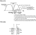
- FIG. 2 (A) shows the relation between the opening areas of inlet and outlet valves and the opening area of the fuel gas injection hole 6a with respect to the time (or the crank angle), and FIG. 2(B) shows a relative positional relation between the projection 5 of the inlet valve 3 and the fuel gas injection holes 6a of the sleeve 6.
- the overlapping portion of an outlet valve opening area E and an inlet valve opening area S is the overlap period in which the inlet and outlet valves are both opened.
- B represents the case of an elongated fuel gas injection hole 6a
- C represents the fuel gas injection starting timing of a circular fuel gas injection hole 6b
- B' and C' each represent the fuel gas injection stopping timing.
- G solid line
- J broken line
- the starting end X of the projection 5 of the inlet valve rod 4 is at the position A, so that the fuel gas supply path 7 and the inlet path 2 in FIG. 1 do not communicate with each other.
- FIG. 3 (A) shows the shape of the fuel gas injection hole 6a as one example of the present invention
- FIG. 3(B) shows the conventional shape thereof.
- each fuel gas injection hole 6a is formed in an elongated shape in parallel with the axis of the sleeve 6.
- the eight fuel gas injection holes 6a are spaced substantially equidistantly along the outer circumference of the sleeve 6.
- each fuel gas injection hole 6b has a circular shape, so that the circulation resistance against the fuel gas is small. Accordingly, the fuel gas tends to be injected in a larger amount in a shorter time.
- the opening and closing operation is performed in a shorter period (crank angle) than for the opening area G (solid line) of the elongated fuel gas injection hole 6a.
- the position at which the staring end X reaches the starting end B of the injection hole 6a is formed at a position (the fuel gas injection timing advance direction) allowing the starting end X to reach the starting end B earlier than for the opening position of the circular fuel gas injection hole 6b by n.
- the amount of n may be appropriately decided by the specification of the engine.
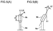
- the distance between centers of the radii R at opposite ends (between elongated hole axes) H is sufficiently larger than the radius R at each opposite end.
- the fuel gas injection hole 6a provided in the sleeve 6 has a configuration in which the region of the opening upper and lower ends of the elongated hole is disposed within the sliding region of the projection 5, and thereby to be opened and closed.
- the elongated hole axis L2 of the elongated fuel gas injection hole 6a may be formed with a tilt angle ⁇ with respect to the axis L1 of the sleeve 6.
- FIG. 4 shows a comparison view of the combustion test results according to the shape of the fuel gas injection hole 6a.
- No. 1 is for a conventional circular shape; No. 2, for a first example of the present invention; No. 3, for a second example of the present invention; and No. 4, for the case where No. 2 is adapted to a mirror engine.
- the fuel gas injection hole total area is 1017 mm 2 .
- the flow rate resistance against the fuel gas is small due to the circular shape. Accordingly, a fuel gas was introduced into the inlet path in a short period. As a result, presumably, it was not possible to sufficiently stir the fuel gas in the combustion chamber 10. This results in the combustion evaluation not posing a practical problem, but leaving room for improvement.
- the shape is an elongated hole, and the radius R is reduced. Accordingly, the injection time increases by the length equivalent to the increase in fluid gas flow rate resistance, so that stirring with the sucked air sufficiently proceeds, resulting in substantially satisfactory combustion.
- the shape is an elongated hole, and the radius R is reduced. Accordingly, the injection time increases by the length equivalent to a further increase in fuel gas flow rate resistance relative to No.2, so that stirring with the sucked air proceeds, resulting in satisfactory combustion.
- No. 4 is the result of a test of the case where the same shape as that of No. 2 is adopted, and is applied to a mirror engine, and shows the case where the opening timing of the inlet valve 3 is delayed by m.
- the inlet valve opening period is shortened, and the opening area of the fuel gas injection hole is 973 mm 2 (the shaded area of FIG. 4 is closed). As a result, it was not possible to supply a required amount of the fuel gas.
- the fuel gas injection holes 6a provided in the sleeve 6 are configured to be disposed within the sliding region of the projection 5 of the inlet valve 3, and thereby to be opened and closed. For this reason, for R and the center distance H (between elongated hole axes), the ratio of R/H may be determined based on the sliding region of the projection 5 of the inlet valve 3.
- the fuel gas injection hole 6a in the shape of an elongated hole, the introduction time of a fuel gas into the inlet tube 2 is ensured. This promotes stirring of air and the fuel gas, which can provide best combustion. Accordingly, the combustion efficiency in the combustion chamber is improved, and the fuel consumption rate is improved.
- the invention is desirably used for a fuel gas supply device of a gas engine in which the injection part of a fuel gas for supplying the fuel gas into the inlet path is prevented from protruding into the inlet path, thereby to reduce the circulation resistance against the sucked air flowing in the inlet path.
Landscapes
- Engineering & Computer Science (AREA)
- Mechanical Engineering (AREA)
- General Engineering & Computer Science (AREA)
- Chemical & Material Sciences (AREA)
- Combustion & Propulsion (AREA)
- Chemical Kinetics & Catalysis (AREA)
- General Chemical & Material Sciences (AREA)
- Oil, Petroleum & Natural Gas (AREA)
- Physics & Mathematics (AREA)
- Geometry (AREA)
- Fuel-Injection Apparatus (AREA)
- Output Control And Ontrol Of Special Type Engine (AREA)
Claims (5)
- Dispositif d'alimentation d'un moteur à gaz en gaz combustible, permettant d'introduire un gaz combustible dans un trajet d'admission (2) par un mouvement vertical d'une tige (4) de soupape d'admission par l'ouverture et la fermeture d'une soupape d'admission (3),
le dispositif comprenant :une saillie (5) formée sur une partie dans une direction axiale de la tige (4) de soupape d'admission et ayant un diamètre externe plus grand qu'une surface environnante de celui-ci,une chemise (6) dans laquelle la saillie (5) est montée coulissante, etun orifice d'injection (6a) de gaz combustible formé dans la chemise (6) et le trajet d'admission (2) avec un mouvement descendant de la saillie (5) de la tige (4) de soupape d'admissioncaractérisé en ce quel'orifice d'injection (6a) de combustible formé dans la chemise (6) possède une forme d'orifice allongé se prolongeant dans la direction axiale de la chemise et établit une communication entre une partie interne de la chemise (6). - Dispositif d'alimentation d'un moteur à gaz en gaz combustible selon la revendication 1, dans lequel un bord terminal supérieur de l'orifice d'injection (6a) de gaz combustible est déplacé dans une direction d'avancée de calage d'injection du gaz combustible.
- Dispositif d'alimentation d'un moteur à gaz en gaz combustible selon la revendication 1, dans lequel l'orifice d'injection (6a) de gaz combustible est conçu de façon qu'un rayon R à chaque extrémité et qu'une distance H entre les centres des rayons R aux extrémités opposées (entre les axes de l'orifice allongé) satisfasse la relation rayon R < distance H entre les centres.
- Dispositif d'alimentation d'un moteur à gaz en gaz combustible selon la revendication 1, dans lequel l'orifice d'injection (6a) de gaz combustible est conçu de façon qu'un rapport R/H d'un rayon R à chaque extrémité et d'une distance H entre les centres des rayons R aux extrémités opposées (entre les axes de l'orifice allongé) soit situé dans la plage suivante : 0,2 R/H ≤ 1,3.
- Dispositif d'alimentation d'un moteur à gaz en gaz combustible selon la revendication 1, dans lequel un axe L2 d'orifice allongé de l'orifice d'injection (6a) de gaz combustible est incliné par rapport à un axe L1 de la chemise (6).
Applications Claiming Priority (1)
| Application Number | Priority Date | Filing Date | Title |
|---|---|---|---|
| PCT/JP2011/058126 WO2012131957A1 (fr) | 2011-03-30 | 2011-03-30 | Dispositif d'alimentation en gaz combustible pour moteur à gaz |
Publications (3)
| Publication Number | Publication Date |
|---|---|
| EP2693006A1 EP2693006A1 (fr) | 2014-02-05 |
| EP2693006A4 EP2693006A4 (fr) | 2014-09-10 |
| EP2693006B1 true EP2693006B1 (fr) | 2016-03-30 |
Family
ID=46929780
Family Applications (1)
| Application Number | Title | Priority Date | Filing Date |
|---|---|---|---|
| EP11862480.8A Active EP2693006B1 (fr) | 2011-03-30 | 2011-03-30 | Dispositif d'alimentation en gaz combustible pour moteur à gaz |
Country Status (6)
| Country | Link |
|---|---|
| US (1) | US20130333667A1 (fr) |
| EP (1) | EP2693006B1 (fr) |
| JP (1) | JP5611449B2 (fr) |
| KR (1) | KR101452149B1 (fr) |
| CN (1) | CN103443409B (fr) |
| WO (1) | WO2012131957A1 (fr) |
Families Citing this family (4)
| Publication number | Priority date | Publication date | Assignee | Title |
|---|---|---|---|---|
| CN102900487B (zh) * | 2012-10-24 | 2015-05-20 | 江苏新能动力科技股份有限公司 | 一种活塞气门装置 |
| EP3181855B1 (fr) * | 2015-12-14 | 2018-08-29 | Caterpillar Energy Solutions GmbH | Préchambre de moteur à combustion interne |
| US10787939B1 (en) * | 2019-04-01 | 2020-09-29 | Cyclazoom, LLC | Poppet valve for internal combustion engine |
| US11506091B2 (en) | 2021-03-03 | 2022-11-22 | Cyclazoom, LLC | Poppet valve and internal combustion piston engine head including same |
Family Cites Families (20)
| Publication number | Priority date | Publication date | Assignee | Title |
|---|---|---|---|---|
| DE444722C (de) * | 1927-05-27 | Ehrhardt & Sehmer A G | Verfahren zum Betriebe von doppelt wirkenden Viertaktgasmaschinen | |
| GB1007736A (en) * | 1962-07-19 | 1965-10-22 | Walker Mfg Co | Improvements in and relating to internal combustion engines |
| JPS4975918A (fr) * | 1972-11-24 | 1974-07-22 | ||
| JPS5552545U (fr) * | 1978-10-05 | 1980-04-08 | ||
| JPS5931139B2 (ja) * | 1978-10-05 | 1984-07-31 | 松下電器産業株式会社 | 磁気記録再生装置 |
| JPS5730359U (fr) * | 1980-07-28 | 1982-02-17 | ||
| JPS59131575U (ja) * | 1983-02-23 | 1984-09-04 | トヨタ自動車株式会社 | 電子制御機関用燃料噴射弁 |
| JPS63191258U (fr) * | 1987-05-29 | 1988-12-09 | ||
| JP2619088B2 (ja) * | 1989-12-28 | 1997-06-11 | 株式会社日立製作所 | 燃料噴射装置 |
| JP3074763B2 (ja) * | 1991-03-30 | 2000-08-07 | いすゞ自動車株式会社 | 2ストロークエンジン |
| JPH0610672A (ja) * | 1992-06-25 | 1994-01-18 | Isuzu Motors Ltd | 内燃機関 |
| JPH09268923A (ja) | 1996-04-01 | 1997-10-14 | Mitsubishi Motors Corp | ガスエンジンの燃料供給装置 |
| JP3780472B2 (ja) * | 2000-01-27 | 2006-05-31 | 愛三工業株式会社 | 燃料噴射弁 |
| DE10052486A1 (de) * | 2000-10-23 | 2002-05-08 | Bosch Gmbh Robert | Brennstoffeinspritzventil |
| JP3653031B2 (ja) * | 2001-10-30 | 2005-05-25 | 三菱重工業株式会社 | ガスエンジンのガス燃料供給方法及び装置 |
| JP3969247B2 (ja) * | 2001-11-06 | 2007-09-05 | 株式会社デンソー | 燃料噴射弁 |
| JP4099075B2 (ja) * | 2002-05-30 | 2008-06-11 | 株式会社日立製作所 | 燃料噴射弁 |
| JP2005248841A (ja) * | 2004-03-04 | 2005-09-15 | Toyota Motor Corp | 二次空気供給装置 |
| JP5169197B2 (ja) * | 2007-12-17 | 2013-03-27 | 株式会社Ihi | 予混合圧縮着火ディーゼルエンジン |
| JP4988791B2 (ja) * | 2009-06-18 | 2012-08-01 | 日立オートモティブシステムズ株式会社 | 燃料噴射弁 |
-
2011
- 2011-03-30 US US14/002,839 patent/US20130333667A1/en not_active Abandoned
- 2011-03-30 CN CN201180069129.2A patent/CN103443409B/zh active Active
- 2011-03-30 EP EP11862480.8A patent/EP2693006B1/fr active Active
- 2011-03-30 KR KR1020137025170A patent/KR101452149B1/ko active Active
- 2011-03-30 WO PCT/JP2011/058126 patent/WO2012131957A1/fr not_active Ceased
- 2011-03-30 JP JP2013506958A patent/JP5611449B2/ja active Active
Also Published As
| Publication number | Publication date |
|---|---|
| CN103443409A (zh) | 2013-12-11 |
| KR101452149B1 (ko) | 2014-10-16 |
| US20130333667A1 (en) | 2013-12-19 |
| JP5611449B2 (ja) | 2014-10-22 |
| EP2693006A4 (fr) | 2014-09-10 |
| EP2693006A1 (fr) | 2014-02-05 |
| WO2012131957A1 (fr) | 2012-10-04 |
| JPWO2012131957A1 (ja) | 2014-07-24 |
| KR20130125825A (ko) | 2013-11-19 |
| CN103443409B (zh) | 2016-09-14 |
Similar Documents
| Publication | Publication Date | Title |
|---|---|---|
| CN101929410B (zh) | 燃料喷射阀 | |
| EP2693006B1 (fr) | Dispositif d'alimentation en gaz combustible pour moteur à gaz | |
| CN103573515B (zh) | 燃料喷射阀 | |
| US9879793B2 (en) | Control valve for a camshaft adjuster | |
| JP7271420B2 (ja) | ピストンクラウン | |
| JP3989495B2 (ja) | 燃料噴射装置 | |
| JP5257456B2 (ja) | 内燃機関の燃料噴射弁及びその製造方法 | |
| EP2693037B1 (fr) | Dispositif d'alimentation en gaz combustible pour moteur à gaz | |
| FI126814B (fi) | Polttoaineen ruiskutussuutin polttomoottorikonetta varten | |
| KR102011070B1 (ko) | 분사 밸브용 밸브 조립체 및 분사 밸브 | |
| CN107829817A (zh) | 内燃机的活塞 | |
| JP2011153548A (ja) | 噴射ノズル | |
| US20090050104A1 (en) | Valve guide for internal combustion engine having means for mixing fuel | |
| CN108138734B (zh) | 用于内燃机的流体喷射装置 | |
| GB2557266A (en) | Piston bowl | |
| KR101692231B1 (ko) | 분사 펌프 | |
| CN104612876B (zh) | 喷油器和具有其的汽车 | |
| KR101027512B1 (ko) | 흡기조절장치 및 흡기 및 배기 조절장치 | |
| JP2007315244A (ja) | 内燃機関のピストン冷却装置 | |
| EP2811149A1 (fr) | Corps d'étanchéité et aiguille destinée à une soupape d'injection de fluide |
Legal Events
| Date | Code | Title | Description |
|---|---|---|---|
| PUAI | Public reference made under article 153(3) epc to a published international application that has entered the european phase |
Free format text: ORIGINAL CODE: 0009012 |
|
| 17P | Request for examination filed |
Effective date: 20130830 |
|
| AK | Designated contracting states |
Kind code of ref document: A1 Designated state(s): AL AT BE BG CH CY CZ DE DK EE ES FI FR GB GR HR HU IE IS IT LI LT LU LV MC MK MT NL NO PL PT RO RS SE SI SK SM TR |
|
| DAX | Request for extension of the european patent (deleted) | ||
| A4 | Supplementary search report drawn up and despatched |
Effective date: 20140807 |
|
| RIC1 | Information provided on ipc code assigned before grant |
Ipc: F01L 3/20 20060101AFI20140801BHEP Ipc: F01L 3/08 20060101ALI20140801BHEP |
|
| RIC1 | Information provided on ipc code assigned before grant |
Ipc: F01L 3/08 20060101ALI20150814BHEP Ipc: F01L 3/20 20060101AFI20150814BHEP Ipc: F02M 21/02 20060101ALI20150814BHEP Ipc: F02M 21/04 20060101ALI20150814BHEP Ipc: F01L 3/24 20060101ALI20150814BHEP |
|
| GRAP | Despatch of communication of intention to grant a patent |
Free format text: ORIGINAL CODE: EPIDOSNIGR1 |
|
| INTG | Intention to grant announced |
Effective date: 20150930 |
|
| GRAS | Grant fee paid |
Free format text: ORIGINAL CODE: EPIDOSNIGR3 |
|
| GRAA | (expected) grant |
Free format text: ORIGINAL CODE: 0009210 |
|
| AK | Designated contracting states |
Kind code of ref document: B1 Designated state(s): AL AT BE BG CH CY CZ DE DK EE ES FI FR GB GR HR HU IE IS IT LI LT LU LV MC MK MT NL NO PL PT RO RS SE SI SK SM TR |
|
| REG | Reference to a national code |
Ref country code: GB Ref legal event code: FG4D |
|
| REG | Reference to a national code |
Ref country code: CH Ref legal event code: EP |
|
| REG | Reference to a national code |
Ref country code: AT Ref legal event code: REF Ref document number: 785652 Country of ref document: AT Kind code of ref document: T Effective date: 20160415 |
|
| REG | Reference to a national code |
Ref country code: IE Ref legal event code: FG4D |
|
| REG | Reference to a national code |
Ref country code: DE Ref legal event code: R096 Ref document number: 602011024769 Country of ref document: DE |
|
| REG | Reference to a national code |
Ref country code: LT Ref legal event code: MG4D |
|
| PG25 | Lapsed in a contracting state [announced via postgrant information from national office to epo] |
Ref country code: HR Free format text: LAPSE BECAUSE OF FAILURE TO SUBMIT A TRANSLATION OF THE DESCRIPTION OR TO PAY THE FEE WITHIN THE PRESCRIBED TIME-LIMIT Effective date: 20160330 Ref country code: FI Free format text: LAPSE BECAUSE OF FAILURE TO SUBMIT A TRANSLATION OF THE DESCRIPTION OR TO PAY THE FEE WITHIN THE PRESCRIBED TIME-LIMIT Effective date: 20160330 Ref country code: NO Free format text: LAPSE BECAUSE OF FAILURE TO SUBMIT A TRANSLATION OF THE DESCRIPTION OR TO PAY THE FEE WITHIN THE PRESCRIBED TIME-LIMIT Effective date: 20160630 Ref country code: GR Free format text: LAPSE BECAUSE OF FAILURE TO SUBMIT A TRANSLATION OF THE DESCRIPTION OR TO PAY THE FEE WITHIN THE PRESCRIBED TIME-LIMIT Effective date: 20160701 |
|
| REG | Reference to a national code |
Ref country code: NL Ref legal event code: MP Effective date: 20160330 |
|
| REG | Reference to a national code |
Ref country code: AT Ref legal event code: MK05 Ref document number: 785652 Country of ref document: AT Kind code of ref document: T Effective date: 20160330 |
|
| PG25 | Lapsed in a contracting state [announced via postgrant information from national office to epo] |
Ref country code: LV Free format text: LAPSE BECAUSE OF FAILURE TO SUBMIT A TRANSLATION OF THE DESCRIPTION OR TO PAY THE FEE WITHIN THE PRESCRIBED TIME-LIMIT Effective date: 20160330 Ref country code: LT Free format text: LAPSE BECAUSE OF FAILURE TO SUBMIT A TRANSLATION OF THE DESCRIPTION OR TO PAY THE FEE WITHIN THE PRESCRIBED TIME-LIMIT Effective date: 20160330 Ref country code: SE Free format text: LAPSE BECAUSE OF FAILURE TO SUBMIT A TRANSLATION OF THE DESCRIPTION OR TO PAY THE FEE WITHIN THE PRESCRIBED TIME-LIMIT Effective date: 20160330 Ref country code: RS Free format text: LAPSE BECAUSE OF FAILURE TO SUBMIT A TRANSLATION OF THE DESCRIPTION OR TO PAY THE FEE WITHIN THE PRESCRIBED TIME-LIMIT Effective date: 20160330 Ref country code: BE Free format text: LAPSE BECAUSE OF NON-PAYMENT OF DUE FEES Effective date: 20160331 |
|
| PG25 | Lapsed in a contracting state [announced via postgrant information from national office to epo] |
Ref country code: NL Free format text: LAPSE BECAUSE OF FAILURE TO SUBMIT A TRANSLATION OF THE DESCRIPTION OR TO PAY THE FEE WITHIN THE PRESCRIBED TIME-LIMIT Effective date: 20160330 |
|
| PG25 | Lapsed in a contracting state [announced via postgrant information from national office to epo] |
Ref country code: IS Free format text: LAPSE BECAUSE OF FAILURE TO SUBMIT A TRANSLATION OF THE DESCRIPTION OR TO PAY THE FEE WITHIN THE PRESCRIBED TIME-LIMIT Effective date: 20160730 Ref country code: EE Free format text: LAPSE BECAUSE OF FAILURE TO SUBMIT A TRANSLATION OF THE DESCRIPTION OR TO PAY THE FEE WITHIN THE PRESCRIBED TIME-LIMIT Effective date: 20160330 Ref country code: PL Free format text: LAPSE BECAUSE OF FAILURE TO SUBMIT A TRANSLATION OF THE DESCRIPTION OR TO PAY THE FEE WITHIN THE PRESCRIBED TIME-LIMIT Effective date: 20160330 |
|
| REG | Reference to a national code |
Ref country code: CH Ref legal event code: PL |
|
| PG25 | Lapsed in a contracting state [announced via postgrant information from national office to epo] |
Ref country code: SM Free format text: LAPSE BECAUSE OF FAILURE TO SUBMIT A TRANSLATION OF THE DESCRIPTION OR TO PAY THE FEE WITHIN THE PRESCRIBED TIME-LIMIT Effective date: 20160330 Ref country code: ES Free format text: LAPSE BECAUSE OF FAILURE TO SUBMIT A TRANSLATION OF THE DESCRIPTION OR TO PAY THE FEE WITHIN THE PRESCRIBED TIME-LIMIT Effective date: 20160330 Ref country code: SK Free format text: LAPSE BECAUSE OF FAILURE TO SUBMIT A TRANSLATION OF THE DESCRIPTION OR TO PAY THE FEE WITHIN THE PRESCRIBED TIME-LIMIT Effective date: 20160330 Ref country code: PT Free format text: LAPSE BECAUSE OF FAILURE TO SUBMIT A TRANSLATION OF THE DESCRIPTION OR TO PAY THE FEE WITHIN THE PRESCRIBED TIME-LIMIT Effective date: 20160801 Ref country code: CZ Free format text: LAPSE BECAUSE OF FAILURE TO SUBMIT A TRANSLATION OF THE DESCRIPTION OR TO PAY THE FEE WITHIN THE PRESCRIBED TIME-LIMIT Effective date: 20160330 Ref country code: RO Free format text: LAPSE BECAUSE OF FAILURE TO SUBMIT A TRANSLATION OF THE DESCRIPTION OR TO PAY THE FEE WITHIN THE PRESCRIBED TIME-LIMIT Effective date: 20160330 Ref country code: AT Free format text: LAPSE BECAUSE OF FAILURE TO SUBMIT A TRANSLATION OF THE DESCRIPTION OR TO PAY THE FEE WITHIN THE PRESCRIBED TIME-LIMIT Effective date: 20160330 |
|
| REG | Reference to a national code |
Ref country code: IE Ref legal event code: MM4A |
|
| PG25 | Lapsed in a contracting state [announced via postgrant information from national office to epo] |
Ref country code: BE Free format text: LAPSE BECAUSE OF FAILURE TO SUBMIT A TRANSLATION OF THE DESCRIPTION OR TO PAY THE FEE WITHIN THE PRESCRIBED TIME-LIMIT Effective date: 20160330 Ref country code: IT Free format text: LAPSE BECAUSE OF FAILURE TO SUBMIT A TRANSLATION OF THE DESCRIPTION OR TO PAY THE FEE WITHIN THE PRESCRIBED TIME-LIMIT Effective date: 20160330 |
|
| REG | Reference to a national code |
Ref country code: DE Ref legal event code: R097 Ref document number: 602011024769 Country of ref document: DE |
|
| PG25 | Lapsed in a contracting state [announced via postgrant information from national office to epo] |
Ref country code: IE Free format text: LAPSE BECAUSE OF NON-PAYMENT OF DUE FEES Effective date: 20160330 Ref country code: CH Free format text: LAPSE BECAUSE OF NON-PAYMENT OF DUE FEES Effective date: 20160331 Ref country code: DK Free format text: LAPSE BECAUSE OF FAILURE TO SUBMIT A TRANSLATION OF THE DESCRIPTION OR TO PAY THE FEE WITHIN THE PRESCRIBED TIME-LIMIT Effective date: 20160330 Ref country code: LI Free format text: LAPSE BECAUSE OF NON-PAYMENT OF DUE FEES Effective date: 20160331 |
|
| PLBE | No opposition filed within time limit |
Free format text: ORIGINAL CODE: 0009261 |
|
| STAA | Information on the status of an ep patent application or granted ep patent |
Free format text: STATUS: NO OPPOSITION FILED WITHIN TIME LIMIT |
|
| GBPC | Gb: european patent ceased through non-payment of renewal fee |
Effective date: 20160630 |
|
| REG | Reference to a national code |
Ref country code: FR Ref legal event code: ST Effective date: 20170201 |
|
| 26N | No opposition filed |
Effective date: 20170103 |
|
| PG25 | Lapsed in a contracting state [announced via postgrant information from national office to epo] |
Ref country code: FR Free format text: LAPSE BECAUSE OF NON-PAYMENT OF DUE FEES Effective date: 20160530 |
|
| PG25 | Lapsed in a contracting state [announced via postgrant information from national office to epo] |
Ref country code: SI Free format text: LAPSE BECAUSE OF FAILURE TO SUBMIT A TRANSLATION OF THE DESCRIPTION OR TO PAY THE FEE WITHIN THE PRESCRIBED TIME-LIMIT Effective date: 20160330 Ref country code: GB Free format text: LAPSE BECAUSE OF NON-PAYMENT OF DUE FEES Effective date: 20160630 |
|
| PG25 | Lapsed in a contracting state [announced via postgrant information from national office to epo] |
Ref country code: MT Free format text: LAPSE BECAUSE OF FAILURE TO SUBMIT A TRANSLATION OF THE DESCRIPTION OR TO PAY THE FEE WITHIN THE PRESCRIBED TIME-LIMIT Effective date: 20160330 |
|
| PG25 | Lapsed in a contracting state [announced via postgrant information from national office to epo] |
Ref country code: MC Free format text: LAPSE BECAUSE OF FAILURE TO SUBMIT A TRANSLATION OF THE DESCRIPTION OR TO PAY THE FEE WITHIN THE PRESCRIBED TIME-LIMIT Effective date: 20160330 |
|
| PG25 | Lapsed in a contracting state [announced via postgrant information from national office to epo] |
Ref country code: CY Free format text: LAPSE BECAUSE OF FAILURE TO SUBMIT A TRANSLATION OF THE DESCRIPTION OR TO PAY THE FEE WITHIN THE PRESCRIBED TIME-LIMIT Effective date: 20160330 Ref country code: HU Free format text: LAPSE BECAUSE OF FAILURE TO SUBMIT A TRANSLATION OF THE DESCRIPTION OR TO PAY THE FEE WITHIN THE PRESCRIBED TIME-LIMIT; INVALID AB INITIO Effective date: 20110330 |
|
| PG25 | Lapsed in a contracting state [announced via postgrant information from national office to epo] |
Ref country code: MT Free format text: LAPSE BECAUSE OF FAILURE TO SUBMIT A TRANSLATION OF THE DESCRIPTION OR TO PAY THE FEE WITHIN THE PRESCRIBED TIME-LIMIT Effective date: 20160331 Ref country code: TR Free format text: LAPSE BECAUSE OF FAILURE TO SUBMIT A TRANSLATION OF THE DESCRIPTION OR TO PAY THE FEE WITHIN THE PRESCRIBED TIME-LIMIT Effective date: 20160330 Ref country code: LU Free format text: LAPSE BECAUSE OF NON-PAYMENT OF DUE FEES Effective date: 20160330 Ref country code: MK Free format text: LAPSE BECAUSE OF FAILURE TO SUBMIT A TRANSLATION OF THE DESCRIPTION OR TO PAY THE FEE WITHIN THE PRESCRIBED TIME-LIMIT Effective date: 20160330 |
|
| PG25 | Lapsed in a contracting state [announced via postgrant information from national office to epo] |
Ref country code: BG Free format text: LAPSE BECAUSE OF FAILURE TO SUBMIT A TRANSLATION OF THE DESCRIPTION OR TO PAY THE FEE WITHIN THE PRESCRIBED TIME-LIMIT Effective date: 20160330 |
|
| REG | Reference to a national code |
Ref country code: DE Ref legal event code: R082 Ref document number: 602011024769 Country of ref document: DE Representative=s name: HOFFMANN - EITLE PATENT- UND RECHTSANWAELTE PA, DE Ref country code: DE Ref legal event code: R081 Ref document number: 602011024769 Country of ref document: DE Owner name: MITSUBISHI HEAVY INDUSTRIES ENGINE & TURBOCHAR, JP Free format text: FORMER OWNER: MITSUBISHI HEAVY INDUSTRIES, LTD., TOKYO, JP |
|
| PG25 | Lapsed in a contracting state [announced via postgrant information from national office to epo] |
Ref country code: AL Free format text: LAPSE BECAUSE OF FAILURE TO SUBMIT A TRANSLATION OF THE DESCRIPTION OR TO PAY THE FEE WITHIN THE PRESCRIBED TIME-LIMIT Effective date: 20160330 |
|
| PGFP | Annual fee paid to national office [announced via postgrant information from national office to epo] |
Ref country code: DE Payment date: 20260204 Year of fee payment: 16 |