WO2012131957A1 - Dispositif d'alimentation en gaz combustible pour moteur à gaz - Google Patents
Dispositif d'alimentation en gaz combustible pour moteur à gaz Download PDFInfo
- Publication number
- WO2012131957A1 WO2012131957A1 PCT/JP2011/058126 JP2011058126W WO2012131957A1 WO 2012131957 A1 WO2012131957 A1 WO 2012131957A1 JP 2011058126 W JP2011058126 W JP 2011058126W WO 2012131957 A1 WO2012131957 A1 WO 2012131957A1
- Authority
- WO
- WIPO (PCT)
- Prior art keywords
- fuel gas
- intake valve
- gas injection
- valve rod
- injection hole
- Prior art date
- Legal status (The legal status is an assumption and is not a legal conclusion. Google has not performed a legal analysis and makes no representation as to the accuracy of the status listed.)
- Ceased
Links
Images


Classifications
-
- F—MECHANICAL ENGINEERING; LIGHTING; HEATING; WEAPONS; BLASTING
- F02—COMBUSTION ENGINES; HOT-GAS OR COMBUSTION-PRODUCT ENGINE PLANTS
- F02M—SUPPLYING COMBUSTION ENGINES IN GENERAL WITH COMBUSTIBLE MIXTURES OR CONSTITUENTS THEREOF
- F02M69/00—Low-pressure fuel-injection apparatus ; Apparatus with both continuous and intermittent injection; Apparatus injecting different types of fuel
-
- F—MECHANICAL ENGINEERING; LIGHTING; HEATING; WEAPONS; BLASTING
- F01—MACHINES OR ENGINES IN GENERAL; ENGINE PLANTS IN GENERAL; STEAM ENGINES
- F01L—CYCLICALLY OPERATING VALVES FOR MACHINES OR ENGINES
- F01L3/00—Lift-valve, i.e. cut-off apparatus with closure members having at least a component of their opening and closing motion perpendicular to the closing faces; Parts or accessories thereof
- F01L3/20—Shapes or constructions of valve members, not provided for in preceding subgroups of this group
-
- F—MECHANICAL ENGINEERING; LIGHTING; HEATING; WEAPONS; BLASTING
- F01—MACHINES OR ENGINES IN GENERAL; ENGINE PLANTS IN GENERAL; STEAM ENGINES
- F01L—CYCLICALLY OPERATING VALVES FOR MACHINES OR ENGINES
- F01L3/00—Lift-valve, i.e. cut-off apparatus with closure members having at least a component of their opening and closing motion perpendicular to the closing faces; Parts or accessories thereof
- F01L3/08—Valves guides; Sealing of valve stem, e.g. sealing by lubricant
-
- F—MECHANICAL ENGINEERING; LIGHTING; HEATING; WEAPONS; BLASTING
- F01—MACHINES OR ENGINES IN GENERAL; ENGINE PLANTS IN GENERAL; STEAM ENGINES
- F01L—CYCLICALLY OPERATING VALVES FOR MACHINES OR ENGINES
- F01L3/00—Lift-valve, i.e. cut-off apparatus with closure members having at least a component of their opening and closing motion perpendicular to the closing faces; Parts or accessories thereof
- F01L3/24—Safety means or accessories, not provided for in preceding sub- groups of this group
-
- F—MECHANICAL ENGINEERING; LIGHTING; HEATING; WEAPONS; BLASTING
- F02—COMBUSTION ENGINES; HOT-GAS OR COMBUSTION-PRODUCT ENGINE PLANTS
- F02M—SUPPLYING COMBUSTION ENGINES IN GENERAL WITH COMBUSTIBLE MIXTURES OR CONSTITUENTS THEREOF
- F02M21/00—Apparatus for supplying engines with non-liquid fuels, e.g. gaseous fuels stored in liquid form
- F02M21/02—Apparatus for supplying engines with non-liquid fuels, e.g. gaseous fuels stored in liquid form for gaseous fuels
- F02M21/0218—Details on the gaseous fuel supply system, e.g. tanks, valves, pipes, pumps, rails, injectors or mixers
- F02M21/0248—Injectors
- F02M21/0257—Details of the valve closing elements, e.g. valve seats, stems or arrangement of flow passages
- F02M21/026—Lift valves, i.e. stem operated valves
-
- F—MECHANICAL ENGINEERING; LIGHTING; HEATING; WEAPONS; BLASTING
- F02—COMBUSTION ENGINES; HOT-GAS OR COMBUSTION-PRODUCT ENGINE PLANTS
- F02M—SUPPLYING COMBUSTION ENGINES IN GENERAL WITH COMBUSTIBLE MIXTURES OR CONSTITUENTS THEREOF
- F02M21/00—Apparatus for supplying engines with non-liquid fuels, e.g. gaseous fuels stored in liquid form
- F02M21/02—Apparatus for supplying engines with non-liquid fuels, e.g. gaseous fuels stored in liquid form for gaseous fuels
- F02M21/04—Gas-air mixing apparatus
- F02M21/042—Mixer comprising a plurality of bores or flow passages
-
- F—MECHANICAL ENGINEERING; LIGHTING; HEATING; WEAPONS; BLASTING
- F01—MACHINES OR ENGINES IN GENERAL; ENGINE PLANTS IN GENERAL; STEAM ENGINES
- F01L—CYCLICALLY OPERATING VALVES FOR MACHINES OR ENGINES
- F01L2820/00—Details on specific features characterising valve gear arrangements
- F01L2820/01—Absolute values
-
- F—MECHANICAL ENGINEERING; LIGHTING; HEATING; WEAPONS; BLASTING
- F01—MACHINES OR ENGINES IN GENERAL; ENGINE PLANTS IN GENERAL; STEAM ENGINES
- F01L—CYCLICALLY OPERATING VALVES FOR MACHINES OR ENGINES
- F01L2820/00—Details on specific features characterising valve gear arrangements
- F01L2820/02—Formulas
-
- Y—GENERAL TAGGING OF NEW TECHNOLOGICAL DEVELOPMENTS; GENERAL TAGGING OF CROSS-SECTIONAL TECHNOLOGIES SPANNING OVER SEVERAL SECTIONS OF THE IPC; TECHNICAL SUBJECTS COVERED BY FORMER USPC CROSS-REFERENCE ART COLLECTIONS [XRACs] AND DIGESTS
- Y02—TECHNOLOGIES OR APPLICATIONS FOR MITIGATION OR ADAPTATION AGAINST CLIMATE CHANGE
- Y02T—CLIMATE CHANGE MITIGATION TECHNOLOGIES RELATED TO TRANSPORTATION
- Y02T10/00—Road transport of goods or passengers
- Y02T10/10—Internal combustion engine [ICE] based vehicles
- Y02T10/30—Use of alternative fuels, e.g. biofuels
Definitions
- the present invention relates to a fuel gas supply device that supplies fuel gas of a gas engine into an intake passage.
- an injection nozzle is connected to a gas supply pipe, and fuel gas is injected from the nozzle into an air supply manifold. is there.
- the fuel gas injection nozzle protrudes into the intake manifold, the air flow in the intake manifold is disturbed, and the flow resistance of the intake air tends to increase.
- a gas injection nozzle is provided across the intake pipe as disclosed in, for example, Japanese Patent Laid-Open No. 9-268923 (Patent Document 1).
- the gas injection nozzle becomes a resistance against the flow of the intake air, the amount of pumping work required for intake of fresh air into the cylinder or fresh air containing fuel is increased, and the fuel consumption rate is increased.
- Patent Document 2 Japanese Patent No. 3653301 (Patent Document 2), as shown in the attached FIG. 1 (A) when the intake valve is closed and when the intake valve is opened, 1 is the cylinder head, 2 is the intake passage in the cylinder head 1 3 is an intake valve, and 4 is an intake valve rod of the intake valve 3.
- the intake valve rod 4 is provided with a protrusion 5 having a cylindrical surface 5 a which is larger than the diameter of the intake valve rod 4 and is parallel to the intake valve rod 4 concentric with the intake valve rod 4.
- a cylindrical surface 5 a of the protrusion 5 is slidably fitted to a sleeve 6 fixed to the cylinder head 1 so as to protrude into the intake passage 2 in the cylinder head 1.
- the sleeve 6 is provided with a plurality of fuel gas injection holes 6a.
- the present invention has been made to solve such problems, and the movement of the protrusion of the intake valve rod on the inner peripheral surface of a sleeve that slidably fits the protrusion provided on the intake valve rod.
- the fuel gas injection hole which is positioned within the range and is opened and closed as the intake valve rod moves is formed into an oval shape, thereby extending the injection time of the fuel gas injected into the intake passage and The purpose is to promote the mixing with the supply air flowing through the combustion chamber, improve the combustion efficiency in the combustion chamber, and improve the fuel consumption rate.
- the present invention provides a fuel gas supply device for a gas engine that supplies fuel gas to an intake passage by vertically moving an intake valve rod by opening and closing an intake valve.
- a protrusion formed in a part in the axial direction of the intake valve rod, and having a larger outer diameter than the vicinity thereof;
- a fuel gas injection hole formed in the sleeve in a long oval shape in the axial direction of the sleeve and communicating the inside of the sleeve with the intake passage as the intake valve rod moves downward; It is characterized by providing.
- the upper end edge of the ellipse of the fuel gas injection hole is moved in the fuel gas injection timing advance direction.
- the fuel gas injection hole becomes an ellipse, and the amount of fuel gas injection at the beginning of fuel gas injection is reduced. Therefore, by moving the fuel gas in the fuel gas injection timing advance direction, The fuel gas injection amount is ensured and the stirring of the air and the fuel gas is promoted.
- the ellipse of the fuel gas injection hole has a radius R at an end portion and a center length H (between the ellipse axes) of the radius R at both ends. It is good to make it H.
- the ellipse of the fuel gas injection hole has a ratio R / H between the radius R of the end portion and the center length L (between the ellipse axes) of the radius R of both end portions.
- a range of 0.2 ⁇ R / H ⁇ 1.3 is preferable.
- the ellipse axis L2 of the fuel gas injection hole is inclined with respect to the axis L1 of the sleeve.
- the sliding contact position between the outer peripheral surface of the protruding portion of the intake valve rod and the peripheral edge of the fuel gas injection hole changes in the circumferential direction during operation of the intake valve while the intake valve is operating in the vertical direction. Therefore, damage to the outer peripheral surface and partial increase in wear can be suppressed.
- the projecting portion provided on the intake valve rod is slidably fitted on the inner peripheral surface of the sleeve within the movement range of the projecting portion of the intake valve rod, and opens and closes as the intake valve rod moves.
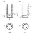
- FIG. 3 (A) shows the shape figure of the fuel gas injection hole of the sleeve which concerns on this invention
- (B) shows the shape figure of the fuel gas injection hole of a prior art
- (C) shows the Y arrow view of (A).
- (D) shows a Z arrow view of (B).
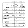
- the comparison figure of the test result by the shape of the fuel gas injection hole of this invention is shown.
- the F arrow figure of FIG. 3 (A) is shown.
- 1, 1 is a cylinder head
- 2 is an intake passage in the cylinder head
- 3 is an intake valve
- 4 is an intake valve rod of the intake valve 3.
- the intake valve rod 4 is provided with a protrusion 5 having a cylindrical surface 5 a which is larger than the diameter of the intake valve rod 4 and is parallel to the intake valve rod 4 concentric with the intake valve rod 4.
- a cylindrical surface 5 a of the protrusion 5 is slidably fitted to a sleeve 6 (commonly known as a gas valve seat) fixed to the cylinder head 1 so as to protrude into the intake passage 2 in the cylinder head 1.
- the cylinder head 1 is provided with an intake valve 3, FIG. 1A shows the case where the intake valve 3 is closed, and FIG. The fully open case is shown.
- the intake valve rod 4 of the intake valve 3 is shown cut in the middle, but penetrates the cylinder head 1 and is reciprocated vertically by a valve drive device (not shown) to open and close the intake port 9.
- the cylinder head 1 is provided with an exhaust valve (not shown).
- the intake valve 3 and the exhaust valve are reciprocally driven so as to open and close the supply / exhaust port at a predetermined timing by a valve driving device (not shown) mechanically connected to a crankshaft (not shown) by a timing gear or the like.
- the fuel gas injection hole 6 a disposed in the sleeve 6 is disposed within the sliding range of the protruding portion 5 of the intake valve 3.
- the fuel gas injection hole 6 a In the position of the intake valve 3 shown in FIG. 1 (A), the fuel gas injection hole 6 a is closed, and the fuel gas supply path 7 and the intake path 2 are isolated by the protrusion of the intake valve 3.
- FIG. 1B the intake valve 3 is in a fully open state, and the fuel gas supply passage 7 and the intake passage 2 have a gap 8 between the outer periphery of the intake valve rod 4 and the inner periphery of the sleeve 6 and the fuel in the sleeve 6.
- the fuel gas communicated via the gas injection holes 6a is injected radially in the direction from the fuel gas injection holes 6a toward the intake passage 2.
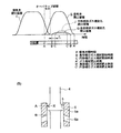
- FIG. 2A shows the relationship between the opening area of the intake / exhaust valve and the opening area of the fuel gas injection hole 6a with respect to time (or crank angle), and FIG. 2B shows the protrusion 5 and the sleeve 6 of the intake valve 3.
- the relative positional relationship of the fuel gas injection hole 6a is shown.
- a portion where the exhaust valve opening area E and the intake valve opening area S overlap is an overlap period in which both the intake and exhaust valves are open.
- B indicates the case of the oval fuel gas injection hole 6a
- C indicates the fuel gas injection start timing of the circular fuel gas injection hole 6b
- B 'and C' indicate the fuel gas injection closing timing, respectively.
- G indicates the opening area of the oval fuel gas injection hole 6a
- J indicates the opening area of the circular fuel gas injection hole 6b.
- the opening area of G (solid line) and the opening area of J (broken line) are substantially the same.
- FIG. 3A shows the shape of the fuel gas injection hole 6a as an embodiment of the present application
- FIG. 3B shows the conventional shape
- the fuel gas injection hole 6 a is formed in an oval shape parallel to the axis of the sleeve 6.
- the oval shape is formed with eight fuel gas injection holes 6a inclined obliquely downward from the inner surface of the sleeve 6 along the outer peripheral surface.
- Eight of the fuel gas injection holes 6 a are arranged at substantially equal intervals along the outer periphery of the sleeve 6.
- the fuel gas injection hole 6b has a circular shape, and the flow resistance of the fuel gas is small, so that the fuel gas is injected in a short time. There is a tendency.
- the opening / closing operation is performed in a period (crank angle) where the opening area J (broken line) of the circular fuel gas injection hole 6b is shorter than the opening area G (solid line) of the oval fuel gas injection hole 6a. It has been broken. Therefore, in the case of the oval fuel gas injection hole 6a, the position where the start end X reaches the start end B of the injection hole 6a is a position that is earlier by n than the opening position of the circular fuel gas injection hole 6b (fuel gas injection Timing advance direction).
- the amount of n may be appropriately determined according to engine specifications. Further, as shown in FIG. 5 (A) as viewed in the direction of arrow F in FIG. 3 (A), the ellipse shape has a sufficient distance R between the centers of the radius R at both ends (between the ellipse axes) H with respect to the radius R at both ends. Is getting bigger.
- the fuel gas injection hole 6a provided in the sleeve 6 has a structure in which an oval open upper and lower end range is disposed within a sliding range of the protruding portion 5 of the intake valve 3 and is opened and closed.
- FIG. 5B when the arrow F in FIG. 3A is shown in FIG.
- the oval axis L2 of the oval fuel gas injection hole 6a is inclined with respect to the axis L1 of the sleeve 6. It may be formed with an angle ⁇ .
- the sliding contact position between the outer peripheral surface 5a of the protrusion 5 of the intake valve rod 4 and the peripheral edge of the fuel gas injection hole 6a changes in the circumferential direction during the operation of the intake valve. Damage to the outer peripheral surface and wear can be suppressed.
- FIG. 4 shows a comparison diagram of the combustion test result according to the shape of the fuel gas injection hole 6a.
- the numerical value of a list shows an example by experiment.
- NO. 1 is a conventional circular shape
- NO. 2 is a first example of the present invention
- NO. 3 is a second example of the present invention
- NO. 4 is NO. This is a case where 2 is made to correspond to the mirror engine.
- NO. 1 the total area of the fuel gas injection holes is 1017 mm 2 , the flow resistance of the fuel gas is small due to the circular shape, and the fuel gas is introduced into the intake passage in a short time, and the combustion chamber It is presumed that the fuel gas could not be sufficiently stirred in No. 10, and there is no problem in practical use, but the combustion evaluation leaves room for improvement.
- the total area of the fuel gas injection holes is NO. Greater than 1.
- the ellipse was used and the radius R was reduced, the fuel gas flow resistance increased, and the injection time was increased, stirring with the intake air progressed, and combustion was substantially satisfactory.
- the total area of the fuel gas injection holes is NO. Less than 1.
- NO. 4 is NO.
- the same shape as in Fig. 2 was applied to the mirror cycle engine, and the case where the opening timing of the intake valve 3 was delayed by m was shown.
- the opening area of the gas injection hole was 973 mm 2 (the shaded portion in FIG. 4 was closed), and the required amount of fuel gas could not be supplied. Accordingly, since the fuel gas injection hole 6a provided in the sleeve 6 is disposed within the sliding range of the protrusion 5 of the intake valve 3 and is opened and closed, the ellipse R and the center length H (long) For the circle axis), the ratio of R / H may be determined based on the sliding range of the protrusion 5 of the intake valve 3.
- the fuel gas injection hole 6a is formed into an oval shape to ensure the introduction time of the fuel gas into the intake pipe 2, thereby promoting the agitation of the air and the fuel gas. Combustion can be obtained, combustion efficiency in the combustion chamber is improved, and fuel consumption rate is improved.
- the fuel gas injection unit for supplying the fuel gas into the intake passage may be prevented from projecting into the intake passage so that the flow resistance of the intake air flowing through the intake passage is reduced.
Landscapes
- Engineering & Computer Science (AREA)
- Mechanical Engineering (AREA)
- General Engineering & Computer Science (AREA)
- Chemical & Material Sciences (AREA)
- Combustion & Propulsion (AREA)
- Chemical Kinetics & Catalysis (AREA)
- General Chemical & Material Sciences (AREA)
- Oil, Petroleum & Natural Gas (AREA)
- Physics & Mathematics (AREA)
- Geometry (AREA)
- Fuel-Injection Apparatus (AREA)
- Output Control And Ontrol Of Special Type Engine (AREA)
Abstract
Priority Applications (6)
| Application Number | Priority Date | Filing Date | Title |
|---|---|---|---|
| US14/002,839 US20130333667A1 (en) | 2011-03-30 | 2011-03-30 | Fuel gas supply device for gas engine |
| JP2013506958A JP5611449B2 (ja) | 2011-03-30 | 2011-03-30 | ガスエンジンの燃料ガス供給装置 |
| PCT/JP2011/058126 WO2012131957A1 (fr) | 2011-03-30 | 2011-03-30 | Dispositif d'alimentation en gaz combustible pour moteur à gaz |
| CN201180069129.2A CN103443409B (zh) | 2011-03-30 | 2011-03-30 | 燃气发动机的可燃气体供给装置 |
| EP11862480.8A EP2693006B1 (fr) | 2011-03-30 | 2011-03-30 | Dispositif d'alimentation en gaz combustible pour moteur à gaz |
| KR1020137025170A KR101452149B1 (ko) | 2011-03-30 | 2011-03-30 | 가스 엔진의 연료 가스 공급 장치 |
Applications Claiming Priority (1)
| Application Number | Priority Date | Filing Date | Title |
|---|---|---|---|
| PCT/JP2011/058126 WO2012131957A1 (fr) | 2011-03-30 | 2011-03-30 | Dispositif d'alimentation en gaz combustible pour moteur à gaz |
Publications (1)
| Publication Number | Publication Date |
|---|---|
| WO2012131957A1 true WO2012131957A1 (fr) | 2012-10-04 |
Family
ID=46929780
Family Applications (1)
| Application Number | Title | Priority Date | Filing Date |
|---|---|---|---|
| PCT/JP2011/058126 Ceased WO2012131957A1 (fr) | 2011-03-30 | 2011-03-30 | Dispositif d'alimentation en gaz combustible pour moteur à gaz |
Country Status (6)
| Country | Link |
|---|---|
| US (1) | US20130333667A1 (fr) |
| EP (1) | EP2693006B1 (fr) |
| JP (1) | JP5611449B2 (fr) |
| KR (1) | KR101452149B1 (fr) |
| CN (1) | CN103443409B (fr) |
| WO (1) | WO2012131957A1 (fr) |
Cited By (1)
| Publication number | Priority date | Publication date | Assignee | Title |
|---|---|---|---|---|
| CN102900487A (zh) * | 2012-10-24 | 2013-01-30 | 江苏新能动力科技股份有限公司 | 一种活塞气门装置 |
Families Citing this family (3)
| Publication number | Priority date | Publication date | Assignee | Title |
|---|---|---|---|---|
| EP3181855B1 (fr) * | 2015-12-14 | 2018-08-29 | Caterpillar Energy Solutions GmbH | Préchambre de moteur à combustion interne |
| US10787939B1 (en) * | 2019-04-01 | 2020-09-29 | Cyclazoom, LLC | Poppet valve for internal combustion engine |
| US11506091B2 (en) | 2021-03-03 | 2022-11-22 | Cyclazoom, LLC | Poppet valve and internal combustion piston engine head including same |
Citations (9)
| Publication number | Priority date | Publication date | Assignee | Title |
|---|---|---|---|---|
| JPS4975918A (fr) * | 1972-11-24 | 1974-07-22 | ||
| JPS5552545U (fr) * | 1978-10-05 | 1980-04-08 | ||
| JPS5730359U (fr) * | 1980-07-28 | 1982-02-17 | ||
| JPS63191258U (fr) * | 1987-05-29 | 1988-12-09 | ||
| JPH04303121A (ja) * | 1991-03-30 | 1992-10-27 | Isuzu Motors Ltd | 2ストロークエンジン |
| JPH0610672A (ja) * | 1992-06-25 | 1994-01-18 | Isuzu Motors Ltd | 内燃機関 |
| JPH09268923A (ja) | 1996-04-01 | 1997-10-14 | Mitsubishi Motors Corp | ガスエンジンの燃料供給装置 |
| JP3653031B2 (ja) | 2001-10-30 | 2005-05-25 | 三菱重工業株式会社 | ガスエンジンのガス燃料供給方法及び装置 |
| WO2009078120A1 (fr) * | 2007-12-17 | 2009-06-25 | Ihi Corporation | Moteur diesel à allumage par compression du pré-mélange |
Family Cites Families (11)
| Publication number | Priority date | Publication date | Assignee | Title |
|---|---|---|---|---|
| DE444722C (de) * | 1927-05-27 | Ehrhardt & Sehmer A G | Verfahren zum Betriebe von doppelt wirkenden Viertaktgasmaschinen | |
| GB1007736A (en) * | 1962-07-19 | 1965-10-22 | Walker Mfg Co | Improvements in and relating to internal combustion engines |
| JPS5931139B2 (ja) * | 1978-10-05 | 1984-07-31 | 松下電器産業株式会社 | 磁気記録再生装置 |
| JPS59131575U (ja) * | 1983-02-23 | 1984-09-04 | トヨタ自動車株式会社 | 電子制御機関用燃料噴射弁 |
| JP2619088B2 (ja) * | 1989-12-28 | 1997-06-11 | 株式会社日立製作所 | 燃料噴射装置 |
| JP3780472B2 (ja) * | 2000-01-27 | 2006-05-31 | 愛三工業株式会社 | 燃料噴射弁 |
| DE10052486A1 (de) * | 2000-10-23 | 2002-05-08 | Bosch Gmbh Robert | Brennstoffeinspritzventil |
| JP3969247B2 (ja) * | 2001-11-06 | 2007-09-05 | 株式会社デンソー | 燃料噴射弁 |
| JP4099075B2 (ja) * | 2002-05-30 | 2008-06-11 | 株式会社日立製作所 | 燃料噴射弁 |
| JP2005248841A (ja) * | 2004-03-04 | 2005-09-15 | Toyota Motor Corp | 二次空気供給装置 |
| JP4988791B2 (ja) * | 2009-06-18 | 2012-08-01 | 日立オートモティブシステムズ株式会社 | 燃料噴射弁 |
-
2011
- 2011-03-30 US US14/002,839 patent/US20130333667A1/en not_active Abandoned
- 2011-03-30 CN CN201180069129.2A patent/CN103443409B/zh active Active
- 2011-03-30 EP EP11862480.8A patent/EP2693006B1/fr active Active
- 2011-03-30 KR KR1020137025170A patent/KR101452149B1/ko active Active
- 2011-03-30 WO PCT/JP2011/058126 patent/WO2012131957A1/fr not_active Ceased
- 2011-03-30 JP JP2013506958A patent/JP5611449B2/ja active Active
Patent Citations (9)
| Publication number | Priority date | Publication date | Assignee | Title |
|---|---|---|---|---|
| JPS4975918A (fr) * | 1972-11-24 | 1974-07-22 | ||
| JPS5552545U (fr) * | 1978-10-05 | 1980-04-08 | ||
| JPS5730359U (fr) * | 1980-07-28 | 1982-02-17 | ||
| JPS63191258U (fr) * | 1987-05-29 | 1988-12-09 | ||
| JPH04303121A (ja) * | 1991-03-30 | 1992-10-27 | Isuzu Motors Ltd | 2ストロークエンジン |
| JPH0610672A (ja) * | 1992-06-25 | 1994-01-18 | Isuzu Motors Ltd | 内燃機関 |
| JPH09268923A (ja) | 1996-04-01 | 1997-10-14 | Mitsubishi Motors Corp | ガスエンジンの燃料供給装置 |
| JP3653031B2 (ja) | 2001-10-30 | 2005-05-25 | 三菱重工業株式会社 | ガスエンジンのガス燃料供給方法及び装置 |
| WO2009078120A1 (fr) * | 2007-12-17 | 2009-06-25 | Ihi Corporation | Moteur diesel à allumage par compression du pré-mélange |
Non-Patent Citations (1)
| Title |
|---|
| See also references of EP2693006A4 * |
Cited By (1)
| Publication number | Priority date | Publication date | Assignee | Title |
|---|---|---|---|---|
| CN102900487A (zh) * | 2012-10-24 | 2013-01-30 | 江苏新能动力科技股份有限公司 | 一种活塞气门装置 |
Also Published As
| Publication number | Publication date |
|---|---|
| CN103443409A (zh) | 2013-12-11 |
| KR101452149B1 (ko) | 2014-10-16 |
| US20130333667A1 (en) | 2013-12-19 |
| JP5611449B2 (ja) | 2014-10-22 |
| EP2693006A4 (fr) | 2014-09-10 |
| EP2693006A1 (fr) | 2014-02-05 |
| EP2693006B1 (fr) | 2016-03-30 |
| JPWO2012131957A1 (ja) | 2014-07-24 |
| KR20130125825A (ko) | 2013-11-19 |
| CN103443409B (zh) | 2016-09-14 |
Similar Documents
| Publication | Publication Date | Title |
|---|---|---|
| JP6072284B2 (ja) | 副室式ガスエンジン | |
| JP5611449B2 (ja) | ガスエンジンの燃料ガス供給装置 | |
| US8051826B2 (en) | Injection system for an internal combustion engine | |
| JP2008057525A (ja) | 内燃機関の吸気構造 | |
| JP5726289B2 (ja) | ガスエンジンの燃料ガス供給装置 | |
| CN107829817A (zh) | 内燃机的活塞 | |
| JP3653031B2 (ja) | ガスエンジンのガス燃料供給方法及び装置 | |
| JP2008151078A (ja) | エンジンの吸気装置 | |
| WO2018099875A1 (fr) | Couronne de piston | |
| US6761141B2 (en) | Valve stem seal with built-in sprue | |
| JP2009236057A (ja) | 燃料噴射弁及び内燃機関 | |
| JP6455085B2 (ja) | ユニフロー掃気式2サイクルエンジン | |
| CN111365152B (zh) | 发动机及其喷油器 | |
| JP2012002205A (ja) | 内燃機関の弁装置 | |
| KR101027512B1 (ko) | 흡기조절장치 및 흡기 및 배기 조절장치 | |
| US20090050104A1 (en) | Valve guide for internal combustion engine having means for mixing fuel | |
| CN221810872U (zh) | 喷油器 | |
| JP2010065603A (ja) | 燃料ポンプの潤滑オイル供給構造 | |
| JP4111122B2 (ja) | ディーゼル機関の燃料噴射装置および燃料噴射方法 | |
| JP2008019803A (ja) | 内燃機関の吸気装置 | |
| JP5404834B2 (ja) | 燃料噴射ポンプ | |
| JP2006307825A (ja) | 筒内直接噴射式内燃機関及び燃料噴射弁 | |
| JP2021080908A (ja) | 内燃機関 | |
| JP2008303783A (ja) | 電磁駆動弁 | |
| JP2009236056A (ja) | 燃料噴射弁及び内燃機関 |
Legal Events
| Date | Code | Title | Description |
|---|---|---|---|
| 121 | Ep: the epo has been informed by wipo that ep was designated in this application |
Ref document number: 11862480 Country of ref document: EP Kind code of ref document: A1 |
|
| WWE | Wipo information: entry into national phase |
Ref document number: 2011862480 Country of ref document: EP |
|
| WWE | Wipo information: entry into national phase |
Ref document number: 14002839 Country of ref document: US |
|
| ENP | Entry into the national phase |
Ref document number: 2013506958 Country of ref document: JP Kind code of ref document: A |
|
| ENP | Entry into the national phase |
Ref document number: 20137025170 Country of ref document: KR Kind code of ref document: A |
|
| NENP | Non-entry into the national phase |
Ref country code: DE |