EP2694833B1 - Scheibenbremsen-kolbendichtungskappe und scheibenbremse damit - Google Patents
Scheibenbremsen-kolbendichtungskappe und scheibenbremse damit Download PDFInfo
- Publication number
- EP2694833B1 EP2694833B1 EP12703747.1A EP12703747A EP2694833B1 EP 2694833 B1 EP2694833 B1 EP 2694833B1 EP 12703747 A EP12703747 A EP 12703747A EP 2694833 B1 EP2694833 B1 EP 2694833B1
- Authority
- EP
- European Patent Office
- Prior art keywords
- fold
- piston
- cap
- articulation
- caliper
- Prior art date
- Legal status (The legal status is an assumption and is not a legal conclusion. Google has not performed a legal analysis and makes no representation as to the accuracy of the status listed.)
- Active
Links
Images
Classifications
-
- F—MECHANICAL ENGINEERING; LIGHTING; HEATING; WEAPONS; BLASTING
- F16—ENGINEERING ELEMENTS AND UNITS; GENERAL MEASURES FOR PRODUCING AND MAINTAINING EFFECTIVE FUNCTIONING OF MACHINES OR INSTALLATIONS; THERMAL INSULATION IN GENERAL
- F16D—COUPLINGS FOR TRANSMITTING ROTATION; CLUTCHES; BRAKES
- F16D65/00—Parts or details
- F16D65/005—Components of axially engaging brakes not otherwise provided for
-
- F—MECHANICAL ENGINEERING; LIGHTING; HEATING; WEAPONS; BLASTING
- F16—ENGINEERING ELEMENTS AND UNITS; GENERAL MEASURES FOR PRODUCING AND MAINTAINING EFFECTIVE FUNCTIONING OF MACHINES OR INSTALLATIONS; THERMAL INSULATION IN GENERAL
- F16D—COUPLINGS FOR TRANSMITTING ROTATION; CLUTCHES; BRAKES
- F16D55/00—Brakes with substantially-radial braking surfaces pressed together in axial direction, e.g. disc brakes
- F16D55/02—Brakes with substantially-radial braking surfaces pressed together in axial direction, e.g. disc brakes with axially-movable discs or pads pressed against axially-located rotating members
- F16D55/22—Brakes with substantially-radial braking surfaces pressed together in axial direction, e.g. disc brakes with axially-movable discs or pads pressed against axially-located rotating members by clamping an axially-located rotating disc between movable braking members, e.g. movable brake discs or brake pads
- F16D55/224—Brakes with substantially-radial braking surfaces pressed together in axial direction, e.g. disc brakes with axially-movable discs or pads pressed against axially-located rotating members by clamping an axially-located rotating disc between movable braking members, e.g. movable brake discs or brake pads with a common actuating member for the braking members
- F16D55/225—Brakes with substantially-radial braking surfaces pressed together in axial direction, e.g. disc brakes with axially-movable discs or pads pressed against axially-located rotating members by clamping an axially-located rotating disc between movable braking members, e.g. movable brake discs or brake pads with a common actuating member for the braking members the braking members being brake pads
- F16D55/226—Brakes with substantially-radial braking surfaces pressed together in axial direction, e.g. disc brakes with axially-movable discs or pads pressed against axially-located rotating members by clamping an axially-located rotating disc between movable braking members, e.g. movable brake discs or brake pads with a common actuating member for the braking members the braking members being brake pads in which the common actuating member is moved axially, e.g. floating caliper disc brakes
- F16D55/2265—Brakes with substantially-radial braking surfaces pressed together in axial direction, e.g. disc brakes with axially-movable discs or pads pressed against axially-located rotating members by clamping an axially-located rotating disc between movable braking members, e.g. movable brake discs or brake pads with a common actuating member for the braking members the braking members being brake pads in which the common actuating member is moved axially, e.g. floating caliper disc brakes the axial movement being guided by one or more pins engaging bores in the brake support or the brake housing
-
- F—MECHANICAL ENGINEERING; LIGHTING; HEATING; WEAPONS; BLASTING
- F16—ENGINEERING ELEMENTS AND UNITS; GENERAL MEASURES FOR PRODUCING AND MAINTAINING EFFECTIVE FUNCTIONING OF MACHINES OR INSTALLATIONS; THERMAL INSULATION IN GENERAL
- F16J—PISTONS; CYLINDERS; SEALINGS
- F16J3/00—Diaphragms; Bellows; Bellows pistons
- F16J3/04—Bellows
- F16J3/041—Non-metallic bellows
- F16J3/042—Fastening details
-
- F—MECHANICAL ENGINEERING; LIGHTING; HEATING; WEAPONS; BLASTING
- F16—ENGINEERING ELEMENTS AND UNITS; GENERAL MEASURES FOR PRODUCING AND MAINTAINING EFFECTIVE FUNCTIONING OF MACHINES OR INSTALLATIONS; THERMAL INSULATION IN GENERAL
- F16J—PISTONS; CYLINDERS; SEALINGS
- F16J3/00—Diaphragms; Bellows; Bellows pistons
- F16J3/04—Bellows
- F16J3/041—Non-metallic bellows
- F16J3/046—Lubrication or venting arrangements
-
- F—MECHANICAL ENGINEERING; LIGHTING; HEATING; WEAPONS; BLASTING
- F16—ENGINEERING ELEMENTS AND UNITS; GENERAL MEASURES FOR PRODUCING AND MAINTAINING EFFECTIVE FUNCTIONING OF MACHINES OR INSTALLATIONS; THERMAL INSULATION IN GENERAL
- F16D—COUPLINGS FOR TRANSMITTING ROTATION; CLUTCHES; BRAKES
- F16D2125/00—Components of actuators
- F16D2125/02—Fluid-pressure mechanisms
- F16D2125/08—Seals, e.g. piston seals
Definitions
- the present invention relates to a disc brake piston cap interposed between the caliper and the piston to protect the piston and the caliper bearing at the outlet of the bore receiving the piston against aggression (liquids, solids).
- this cap being composed of a folded bellows having an outer edge and an inner edge, to be housed in an annular groove of the stirrup, at the outlet of the bore receiving the piston, the outer edge of the cap being fixed to the caliper at the outer side of the annular groove and its inner edge being provided with a bead housed in a groove of the piston.
- Such a cap also called a frustoconical bellows, seals the inner region of the brake piston in the caliper with respect to the outside while allowing the piston to carry out the braking races and to take account of the evolution of the races according to the wear of the brake lining.
- the known piston cap is movable between a retracted position corresponding to the retracted position of the piston, wherein, the different plies are superimposed and an extended position of the piston in which the folds of the cap or bellows are deployed axially and spread between the groove of the piston. the stirrup and the one of the piston.
- the cap thus protects the surface of the piston and the range avoiding contact with foreign bodies, liquids and dust.
- This piston cap includes a folding aid means to prevent tearing of the bellows. Indeed, especially when replacing brake lining, the piston is pushed into its bore. The cap may not fold properly into the groove of the caliper. It is then exposed to contact with metal elements of the brake whose temperature can reach high values, causing after a certain time the deterioration of the bellows. The latter, once torn, can no longer protect the inside of the piston against aggression by liquids or solids, dust or otherwise.
- the cap known, shown in figure 3 , comprises five folds going from the small diameter to the large diameter: an inner fold 101 directed outwards, an intermediate fold 102 directed inwards, an intermediate fold 103 directed outwards, an intermediate fold 104 directed towards the inside and finally, an outer fold 105 directed towards the outside and an overmolded insert 106.
- the bead is fixed and the sealing area is controlled because the burr of the joint plane is outside the sealing area.
- the inner fold of the cap is provided with a bead and has recesses.
- the inner ply and therefore the cap is thus perfectly held on the piston while providing an air leakage passage of the annular groove of the caliper, when the air is compressed under pressure due to its temperature rise.
- the bosses of the bead are constituted by lamellae.
- the inner joints are provided with pins to bear against the bottom of the annular groove of the stirrup while leaving a passage of air between the pins.
- the inner joints are more precisely the side of the joints facing the bottom of the annular groove of the stirrup. This avoids flat contacts between the joints of the cap and the face of the annular groove of the stirrup.
- the seal is broken and all the annular groove of the stirrup is at the same pressure, that is to say a pressure close to the pressure outside.
- the cap On the outer side of the cap, that is to say at the level of the molded insert, it is advantageous that it be reinforced by a flat steel ring-shaped insert, provided with holes, to be completely wrapped. by the material of the cap. This achieves a perfect attachment of the ring to the material of the cap promoting the holding of the cap in the annular groove of the stirrup.
- the operation of the cap is improved if at least one incoming intermediate fold is provided with at least one longitudinal extra thickness on its outwardly facing side and this extra thickness is parallel to the axis of the cap and the axis of the caliper of brake receiving this cap.
- the cap comprises at least one intermediate fold provided near its inner articulation with the adjacent fold, of a local extra thickness, also longitudinally directed, on its side facing inwards, and this local extra thickness is preferably in a position homologous to that of the longitudinal extra thickness of the fold.
- the intermediate fold is provided with several longitudinal thickenings and local thicknesses in positions counterparts, that is to say on both sides of the fold, and these overthicknesses are distributed equiangularly on the fold.
- the invention also relates to a disc brake equipped with a cap as defined above.
- the invention relates to a disc brake piston cap housed between the caliper and the piston to separate the volume outside the brake volume from the inside and protect the piston.
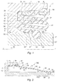
- the figure 1 is an axial half-section of the caliper 1 of the disc brake at the axis xx of the piston 2 received in the bore 12.
- the piston 2 is a cylindrical sleeve whose front face 21 bears against the plate brake following a trace in the form of a circular ring to push the plate against the brake disc.
- the wafer and the not shown brake disc are on the right side of the figure 1 .
- Stirrup 1 comprises an annular groove 11 receiving the cap 3 fixed to the piston 2 in a groove 22.
- the cap 3 has a shape of revolution generated by this section rotating about the axis xx.
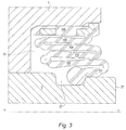
- the cap 3 In the fully deployed state according to figure 2 , the cap 3 has generally a frustoconical shape 3A, the piston occupying the position 2A.
- the section of the cap 3 in the free state or its molding section correspond essentially to the shape of the cap installed between the stirrup 1 and the piston 2 which is the folded or partially folded state.
- the outer side and the inner side are marked with respect to the axis xx in the radial direction, the outer side being away from the axis xx and the inner side being close to the axis xx.
- the incoming direction goes from the outside of the brake inwards in the direction of the arrow Fr to the figure 1 .
- the direction of the outward direction corresponds to the opposite direction going from the inside of the brake towards the outside this by traversing the cap from the bead, towards the molded insert.
- the inner ply 35 carrying the bead 351 is retractable, that is to say turned towards the inside of the groove 11 of the stirrup 1 and not towards the outside.
- the inner ply 35 is located between the groove 22 of the piston 2 and the bottom 112 of the annular groove 11.
- the overmolded insert 31 consists of an insert 36 in the form of a flat steel ring, provided with holes 361 and a raised outer edge 362 so that the rubber of the cap 3 can completely wrap. the insert 36.
- the top of the two joints 331, 342 respectively between the branches 32, 33 and 34, 35 is lined with groups of pins 38.
- the groups of pins 38 of each joint are equiangularly distributed for example at 45 ° periphery and homologous groups on two joints are located on the same rays.
- the fold 33 is reinforced on both sides by the extra thicknesses 334, 335, longitudinal, substantially parallel to the axis xx.
- the extra thickness 334 extends over a large portion of the top of the branch 33 while the extra thickness 335 is located on the inner side of the hinge 331.
- the extra thicknesses are regularly distributed in the peripheral direction of the cap and on one side and the other of the fold, they are preferably in homologous positions, that is to say in the same axial plane.
- the inner ply 35 On its face facing the piston 2, the inner ply 35 is stiffened by longitudinal ribs 352, that is to say directed in the direction of the axis xx (or substantially in this direction) so that the inner ply 35 does not extend to the outside; the deployment movement is provided by the intermediate folds 32, 33, 34.
- the longitudinal ribs 352 create channels between the surface of the piston 2 and the inner ply 35 allowing the passage of air.
- the front face of the bead 351 is provided with channels 353 facilitating the passage of air when the bead 351 bears in the groove 22 of the piston 2.
- the installation of the cap 3 according to the invention in the stirrup 1 and on the piston 2 is done as already described above, namely, the outer edge of the seal 3, that is to say the outer ply 31 is attached to the stirrup 1 and the inner edge is introduced by the bead 351 in the groove 22 of the piston 2.
- the inner surface of the inner ply 35 can be applied more or less against the surface of the piston 2, beyond the groove, 22 and the channels create passages in the direction of the axis xx allowing the hot air pressure to escape outwardly passing through these intervals, then in the groove 22 between the bottom 222 and the bead 351 during its lifting due to pressure.
- the bead 351 bears against the front side 221 of the throat 22; the notches 253 allow the passage of air since the bead 351 is not in contact with the inner side 223 of the groove 22.
- burr 354 of the joint plane of the mold in which the cap 3 is made is situated in the angle between the bottom 222 and the front edge 221 of the groove 22 so that the same irregular burr does not affect the tightness of the assembly.
- the inner ply 35 is naturally inclined by approximately 45 ° with respect to the intermediate ply 34 so as to create in the installed state, an elastic force pushing the bead 351 into the bottom 222 of the throat 22.
- the whole of the annular groove 11 communicates with the outside since the joints 331, 342 can not bear tightly against the bottom 112 of the groove 11 because of the pins 38 and the intervals that they leave between them .
- the cap 3 allows the balancing substantially at atmospheric pressure of the annular groove 11 when the air is compressed during the folding of the cap and / or the volume of air is hot and under pressure.
- the invention thus relates not only to the cap, but also to the brake caliper, the cap of which constitutes an important piece, integrated.
- the invention relates generally to brake systems equipped with disc brakes.
Landscapes
- Engineering & Computer Science (AREA)
- General Engineering & Computer Science (AREA)
- Mechanical Engineering (AREA)
- Braking Arrangements (AREA)
- Sealing Devices (AREA)
- Diaphragms And Bellows (AREA)
Claims (9)
- Scheibenbremsenkolbenkappe, die zwischen dem Bremssattel (1) und dem Kolben (2) angeordnet ist, um den Kolben vor Angriffen (Flüssigkeiten, Feststoffe) zu schützen, wobei diese Kappe aus einem Faltenbalg besteht, der einen Außenrand und einen Innenrand besitzt, um in einer Ringkehle (11) des Bremssattels (1) an der Ausmündung der Bohrung (12), die den Kolben (2) aufnimmt, zu sitzen, wobei der Außenrand der Kappe am Bremssattel in Höhe der Außenseite (111) der Ringkehle (11) befestigt ist und ihr Innenrand mit einem Wulst versehen ist, der in einer Kehle (22) des Kolbens (2) sitzt,
Kolbenkappe, dadurch gekennzeichnet, dass die Innenfalte (35) der Kappe (3) sich zwischen der Kehle (22) des Kolbens (2) und dem Inneren des Bremssattels (1) befindet und sie Längsrippen (352) an ihrer gegen den Kolben (2) anliegenden Fläche aufweist, die den Durchgang von Luft gestatten, und dass die Innenfalte (35), die durch ein Gelenk (342) mit einer abgehenden Zwischenfalte (34) verbunden ist, die selbst durch ein Gelenk (341) mit einer eingehenden Zwischenfalte (33) verbunden ist, welche durch ein Gelenk (331) mit einer, abgehenden, Außenfalte (32) verbunden ist, die selbst durch ein Gelenk (321) mit dem aufgeformten Einsatz (31) verbunden ist, und
die Innengelenke (331, 342) mit Spitzen (38) versehen sind, um sich gegen den Boden (112) der Ringkehle (11) des Bremssattels abzustützen, und gleichzeitig einen Luftdurchgang zwischen den Spitzen beizubehalten. - Bremskolbenkappe nach Anspruch 1,
dadurch gekennzeichnet, dass
die Innenfalte (35) der Kappe (3) mit einem Wulst (351) versehen ist und Kanäle (353) aufweist, um gegen den vorderen Rand (221) der Kehle (22) des Kolbens (2) anzuliegen. - Bremskolbenkappe nach Anspruch 1,
dadurch gekennzeichnet, dass
der aufgeformte Einsatz (31) aus einem Einsatz (36) in Flachringform aus Stahl, der mit Löchern (361) versehen ist, um vollständig vom Material der Kappe umhüllt zu werden, besteht. - Bremskolbenkappe nach Anspruch 3,
dadurch gekennzeichnet, dass
der Einsatz (36) mit einem erhöhten Außenrand (362) versehen ist. - Bremskolbenkappe nach Anspruch 1,
dadurch gekennzeichnet, dass
mindestens eine Zwischenfalte (33) mit mindestens einer Längsverdickung (335) an ihrer Innenseite versehen ist, wobei diese Verdickung parallel zur Achse (xx) ist. - Bremskolbenkappe nach den Ansprüchen 1 und 5,
dadurch gekennzeichnet, dass
mindestens eine Zwischenfalte (33) in der Nähe ihres Gelenks (331) mit der Nachbarfalte (32) mit einer lokalen Verdickung (334) an der Außenseite versehen ist, wobei diese lokale Verdickung sich in einer Position befindet, die zu der ihrer Längsverdickung (335) homolog ist. - Bremskolbenkappe nach Anspruch 6,
dadurch gekennzeichnet, dass
mindestens eine Zwischenfalte (33) mit einander entsprechenden Längsverdickungen (334) und lokalen Verdickungen (335) versehen ist, das heißt, dass diese Verdickungen an beiden Seiten der Falte in gleichen Winkelabständen auf der Falte (33) verteilt sind. - Bremskolbenkappe nach Anspruch 1,
dadurch gekennzeichnet, dass
sie umfasst:- eine eingehende Innenfalte (35), die mit einer Zwischenfalte (34) durch ein Gelenk (342) verbunden ist und durch einen Wulst (351), der in der Kehle (22) des Kolbens (2) sitzt, begrenzt wird,- eine Zwischenfalte (34), die mit einer zweiten Zwischenfalte (33) durch ein Gelenk (341) verbunden ist, und- eine zweite Zwischenfalte (33), die nach innen gewandt ist und durch ein Gelenk (331) mit einer Außenfalte (32) verbunden ist,- eine Außenfalte (32), die nach außen gerichtet ist und an einem aufgeformten Einsatz (31) durch ein Gelenk (321) angelenkt ist,- einen aufgeformten Einsatz (31), um gegen die Außenwand (111) der Ringkehle (11) des Bremssattels (1) anzuliegen. - Bremsscheibe, die eine Kolbenkappe nach einem der Ansprüche 1 bis 8 aufweist.
Priority Applications (1)
| Application Number | Priority Date | Filing Date | Title |
|---|---|---|---|
| PL12703747T PL2694833T3 (pl) | 2011-04-04 | 2012-02-01 | Osłona tłoczka hamulca tarczowego i wyposażony w nią hamulec tarczowy |
Applications Claiming Priority (2)
| Application Number | Priority Date | Filing Date | Title |
|---|---|---|---|
| FR1101022A FR2973462A1 (fr) | 2011-04-04 | 2011-04-04 | Capuchon de piston de frein a disque et frein a disque ainsi equipe |
| PCT/EP2012/051690 WO2012136397A1 (fr) | 2011-04-04 | 2012-02-01 | Capuchon de piston de frein a disque et frein a disque ainsi equipe |
Publications (2)
| Publication Number | Publication Date |
|---|---|
| EP2694833A1 EP2694833A1 (de) | 2014-02-12 |
| EP2694833B1 true EP2694833B1 (de) | 2016-10-05 |
Family
ID=45592350
Family Applications (1)
| Application Number | Title | Priority Date | Filing Date |
|---|---|---|---|
| EP12703747.1A Active EP2694833B1 (de) | 2011-04-04 | 2012-02-01 | Scheibenbremsen-kolbendichtungskappe und scheibenbremse damit |
Country Status (10)
| Country | Link |
|---|---|
| US (1) | US8991565B2 (de) |
| EP (1) | EP2694833B1 (de) |
| JP (1) | JP6110362B2 (de) |
| KR (1) | KR20130120549A (de) |
| CN (1) | CN103477109B (de) |
| ES (1) | ES2609979T3 (de) |
| FR (1) | FR2973462A1 (de) |
| PL (1) | PL2694833T3 (de) |
| RU (1) | RU2571839C2 (de) |
| WO (1) | WO2012136397A1 (de) |
Families Citing this family (11)
| Publication number | Priority date | Publication date | Assignee | Title |
|---|---|---|---|---|
| DE112016002100T5 (de) * | 2015-05-08 | 2018-03-08 | Hitachi Automotive Systems, Ltd. | Scheibenbremse |
| WO2016194607A1 (ja) | 2015-05-29 | 2016-12-08 | イーグル工業株式会社 | 金属ベローズ型アキュムレータ |
| PL3386819T3 (pl) * | 2015-12-10 | 2020-08-24 | Arfesan Arkan Fren Elemanlari Sanayi Ve Ticaret Anonim Sirketi | Pyłoszczelna tarcza ustalająca |
| EA034712B1 (ru) * | 2016-03-18 | 2020-03-12 | Уэир Сларри Груп, Инк. | Уплотнительное устройство для регулируемых элементов насоса |
| US10655733B2 (en) * | 2016-11-18 | 2020-05-19 | Schaublin Sa | Elastomeric seal having impact protecting protrusions |
| KR102454013B1 (ko) * | 2017-10-31 | 2022-10-14 | 현대모비스 주식회사 | 브레이크 장치 |
| MX2020005439A (es) * | 2017-11-28 | 2020-12-03 | Hitachi Astemo Ltd | Disco de freno y cubierta de piston. |
| CN112888872B (zh) * | 2018-09-28 | 2023-08-18 | 大陆汽车科技有限公司 | 用于汽车制动缸的改进的柔性防尘罩 |
| JP7114453B2 (ja) * | 2018-12-19 | 2022-08-08 | 日立Astemo株式会社 | ディスクブレーキ及びピストンブーツ |
| JP7570984B2 (ja) | 2021-07-19 | 2024-10-22 | 曙ブレーキ工業株式会社 | ピストンブーツ及びディスクブレーキ装置 |
| EP4343166A1 (de) * | 2022-09-23 | 2024-03-27 | Meritor Heavy Vehicle Braking Systems (UK) Limited | Bremssattelführungsanordnung |
Family Cites Families (12)
| Publication number | Priority date | Publication date | Assignee | Title |
|---|---|---|---|---|
| US4327925A (en) * | 1979-08-06 | 1982-05-04 | Garlock Inc. | Disc brake boot seal method and article |
| FR2685749B2 (fr) * | 1988-10-28 | 1995-07-21 | Bendix France | Capuchon de piston. |
| FR2684161B1 (fr) * | 1988-10-28 | 1995-06-09 | Bendix France | Capuchon de piston. |
| FR2657136A2 (fr) * | 1990-01-18 | 1991-07-19 | Bendix France | Capuchon de piston. |
| DE4127830A1 (de) * | 1991-08-22 | 1993-02-25 | Teves Gmbh Alfred | Schutzkappe fuer den bremszylinder einer scheibenbremse |
| JPH0814288A (ja) * | 1994-06-29 | 1996-01-16 | Aisin Seiki Co Ltd | ブーツ付嵌合体 |
| FR2723158B1 (fr) * | 1994-07-28 | 1996-09-06 | Alliedsignal Automotive Espana | Patin et frein a disque l'utilisant |
| FR2771148B1 (fr) * | 1997-11-20 | 2000-04-21 | Bosch Syst Freinage | Capuchon de colonnette pour frein a disque a etrier coulissant |
| DE60009757T2 (de) * | 2000-11-30 | 2005-04-28 | Freni Brembo S.P.A., Curno | Schutzkappe für eine Kolbenzylindereinheit einer Scheibenbremse |
| US7097004B2 (en) * | 2003-01-24 | 2006-08-29 | Akebono Corporation (North America) | Pressure bleeding boot-type seal |
| JP2005308059A (ja) * | 2004-04-20 | 2005-11-04 | Shimano Inc | 自転車用ディスクブレーキロータ組立体 |
| FR2941026B1 (fr) * | 2009-01-14 | 2014-02-14 | Bosch Gmbh Robert | Soufflet d'etancheite d'etrier comportant un moyen d'aide au repliage. |
-
2011
- 2011-04-04 FR FR1101022A patent/FR2973462A1/fr active Pending
-
2012
- 2012-02-01 WO PCT/EP2012/051690 patent/WO2012136397A1/fr not_active Ceased
- 2012-02-01 ES ES12703747.1T patent/ES2609979T3/es active Active
- 2012-02-01 PL PL12703747T patent/PL2694833T3/pl unknown
- 2012-02-01 JP JP2014503039A patent/JP6110362B2/ja active Active
- 2012-02-01 US US14/009,708 patent/US8991565B2/en active Active
- 2012-02-01 CN CN201280011623.8A patent/CN103477109B/zh active Active
- 2012-02-01 RU RU2013148819/11A patent/RU2571839C2/ru active
- 2012-02-01 EP EP12703747.1A patent/EP2694833B1/de active Active
- 2012-02-01 KR KR1020137024463A patent/KR20130120549A/ko not_active Ceased
Also Published As
| Publication number | Publication date |
|---|---|
| JP6110362B2 (ja) | 2017-04-05 |
| ES2609979T3 (es) | 2017-04-25 |
| WO2012136397A1 (fr) | 2012-10-11 |
| FR2973462A1 (fr) | 2012-10-05 |
| CN103477109B (zh) | 2016-07-06 |
| EP2694833A1 (de) | 2014-02-12 |
| RU2571839C2 (ru) | 2015-12-20 |
| CN103477109A (zh) | 2013-12-25 |
| US20140110906A1 (en) | 2014-04-24 |
| KR20130120549A (ko) | 2013-11-04 |
| US8991565B2 (en) | 2015-03-31 |
| RU2013148819A (ru) | 2015-05-10 |
| JP2014510244A (ja) | 2014-04-24 |
| PL2694833T3 (pl) | 2017-05-31 |
Similar Documents
| Publication | Publication Date | Title |
|---|---|---|
| EP2694833A1 (de) | Scheibenbremsen-kolbendichtungskappe und scheibenbremse damit | |
| EP1098779B1 (de) | Felgenrad mit nach aussen geneigten schultern | |
| WO2017140637A1 (fr) | Dispositif de bouchage pour un col de récipient | |
| FR2923750A1 (fr) | Pneumatique capable de rouler malgre une perforation,et procede pour sa fabrication. | |
| EP2208917B1 (de) | Faltenbalg eines Bügels, der ein Hilfsmittel zum Zusammenklappen umfasst | |
| FR3032382A1 (fr) | Ensemble roulant | |
| EP1289779B1 (de) | Reifen mit einem verstärkungselement in mindestens einer seitenwand und montierte reifen/felge einheit | |
| EP1868823B1 (de) | Arretierungsring in einer anordnung zur montage eines reifens an einer fahrzeugnabe | |
| FR2940770A1 (fr) | Dispositif de roulage a plat pour vehicule automobile et ensemble monte l'incorporant | |
| EP1345783B1 (de) | Aus einem luftreifen und einem dichtungsteil bestehende einheit und herstellungsverfahren | |
| EP1259387B1 (de) | Felge und einheit aus felge und stützauflage | |
| EP3802151B1 (de) | Flexibler adapter und felgenanordnung für eine rollanordnung | |
| EP1868824B1 (de) | System zur arretierung eines montagerings an einer fahrzeugnabe | |
| FR2809348A1 (fr) | Pneumatique comprenant un profile de renfort dans au moins un flanc et ensemble pneumatique/jante comprenant un tel pneumatique | |
| EP2934907B1 (de) | Anordnung von rad und radgehäuse für einen sammelwagen | |
| FR2511307A1 (fr) | Ensemble d'une roue et d'un pneu sans chambre a air, jante et garniture de securite pour cet ensemble et procede pour diminuer l'echauffement en cas de pneu a plat | |
| WO2001070542A1 (fr) | Accessoire pour flap | |
| FR2553717A1 (fr) | Jante en plusieurs pieces comportant un cercle de blocage perfectionne | |
| FR3023889A1 (fr) | Butee d'embrayage-debrayage, de suspension ou de direction, et vehicule automobile equipe d'une telle butee | |
| EP3484727A1 (de) | Adapter für montierte anordnung mit einem referenzschicht | |
| FR3154157A1 (fr) | Plaquette de frein et procede d’assemblage | |
| FR3037529A1 (fr) | Moyeu de palier a roulement integrant une gorge d'etancheite | |
| FR2809054A1 (fr) | Pneumatique, ensemble pneumatique et jante | |
| FR2923751A1 (fr) | Pneumatique capable de rouler malgre une perforation | |
| FR2887821A1 (fr) | Perfectionnement des ensembles comprenant un boudin permettant de rouler a l'etat degonfle. |
Legal Events
| Date | Code | Title | Description |
|---|---|---|---|
| PUAI | Public reference made under article 153(3) epc to a published international application that has entered the european phase |
Free format text: ORIGINAL CODE: 0009012 |
|
| 17P | Request for examination filed |
Effective date: 20130716 |
|
| AK | Designated contracting states |
Kind code of ref document: A1 Designated state(s): AL AT BE BG CH CY CZ DE DK EE ES FI FR GB GR HR HU IE IS IT LI LT LU LV MC MK MT NL NO PL PT RO RS SE SI SK SM TR |
|
| DAX | Request for extension of the european patent (deleted) | ||
| RIN1 | Information on inventor provided before grant (corrected) |
Inventor name: BINDNER, THIERRY Inventor name: BARRET, PHILIPPE Inventor name: CHAMPION, PASCAL Inventor name: DAGUZAN, FRANCOIS |
|
| RIN1 | Information on inventor provided before grant (corrected) |
Inventor name: BINDNER, THIERRY Inventor name: BARRET, PHILIPPE Inventor name: DAGUZAN, FRANCOIS Inventor name: CHAMPION, PASCAL |
|
| GRAP | Despatch of communication of intention to grant a patent |
Free format text: ORIGINAL CODE: EPIDOSNIGR1 |
|
| INTG | Intention to grant announced |
Effective date: 20160503 |
|
| GRAS | Grant fee paid |
Free format text: ORIGINAL CODE: EPIDOSNIGR3 |
|
| GRAA | (expected) grant |
Free format text: ORIGINAL CODE: 0009210 |
|
| AK | Designated contracting states |
Kind code of ref document: B1 Designated state(s): AL AT BE BG CH CY CZ DE DK EE ES FI FR GB GR HR HU IE IS IT LI LT LU LV MC MK MT NL NO PL PT RO RS SE SI SK SM TR |
|
| REG | Reference to a national code |
Ref country code: GB Ref legal event code: FG4D Free format text: NOT ENGLISH |
|
| REG | Reference to a national code |
Ref country code: CH Ref legal event code: EP |
|
| REG | Reference to a national code |
Ref country code: AT Ref legal event code: REF Ref document number: 834944 Country of ref document: AT Kind code of ref document: T Effective date: 20161015 |
|
| REG | Reference to a national code |
Ref country code: IE Ref legal event code: FG4D Free format text: LANGUAGE OF EP DOCUMENT: FRENCH |
|
| REG | Reference to a national code |
Ref country code: DE Ref legal event code: R096 Ref document number: 602012023708 Country of ref document: DE |
|
| REG | Reference to a national code |
Ref country code: FR Ref legal event code: PLFP Year of fee payment: 6 |
|
| REG | Reference to a national code |
Ref country code: NL Ref legal event code: MP Effective date: 20161005 |
|
| REG | Reference to a national code |
Ref country code: LT Ref legal event code: MG4D |
|
| PG25 | Lapsed in a contracting state [announced via postgrant information from national office to epo] |
Ref country code: LV Free format text: LAPSE BECAUSE OF FAILURE TO SUBMIT A TRANSLATION OF THE DESCRIPTION OR TO PAY THE FEE WITHIN THE PRESCRIBED TIME-LIMIT Effective date: 20161005 |
|
| REG | Reference to a national code |
Ref country code: AT Ref legal event code: MK05 Ref document number: 834944 Country of ref document: AT Kind code of ref document: T Effective date: 20161005 |
|
| REG | Reference to a national code |
Ref country code: ES Ref legal event code: FG2A Ref document number: 2609979 Country of ref document: ES Kind code of ref document: T3 Effective date: 20170425 |
|
| PG25 | Lapsed in a contracting state [announced via postgrant information from national office to epo] |
Ref country code: LT Free format text: LAPSE BECAUSE OF FAILURE TO SUBMIT A TRANSLATION OF THE DESCRIPTION OR TO PAY THE FEE WITHIN THE PRESCRIBED TIME-LIMIT Effective date: 20161005 Ref country code: NO Free format text: LAPSE BECAUSE OF FAILURE TO SUBMIT A TRANSLATION OF THE DESCRIPTION OR TO PAY THE FEE WITHIN THE PRESCRIBED TIME-LIMIT Effective date: 20170105 Ref country code: SE Free format text: LAPSE BECAUSE OF FAILURE TO SUBMIT A TRANSLATION OF THE DESCRIPTION OR TO PAY THE FEE WITHIN THE PRESCRIBED TIME-LIMIT Effective date: 20161005 Ref country code: GR Free format text: LAPSE BECAUSE OF FAILURE TO SUBMIT A TRANSLATION OF THE DESCRIPTION OR TO PAY THE FEE WITHIN THE PRESCRIBED TIME-LIMIT Effective date: 20170106 |
|
| PG25 | Lapsed in a contracting state [announced via postgrant information from national office to epo] |
Ref country code: FI Free format text: LAPSE BECAUSE OF FAILURE TO SUBMIT A TRANSLATION OF THE DESCRIPTION OR TO PAY THE FEE WITHIN THE PRESCRIBED TIME-LIMIT Effective date: 20161005 Ref country code: RS Free format text: LAPSE BECAUSE OF FAILURE TO SUBMIT A TRANSLATION OF THE DESCRIPTION OR TO PAY THE FEE WITHIN THE PRESCRIBED TIME-LIMIT Effective date: 20161005 Ref country code: HR Free format text: LAPSE BECAUSE OF FAILURE TO SUBMIT A TRANSLATION OF THE DESCRIPTION OR TO PAY THE FEE WITHIN THE PRESCRIBED TIME-LIMIT Effective date: 20161005 Ref country code: NL Free format text: LAPSE BECAUSE OF FAILURE TO SUBMIT A TRANSLATION OF THE DESCRIPTION OR TO PAY THE FEE WITHIN THE PRESCRIBED TIME-LIMIT Effective date: 20161005 Ref country code: IS Free format text: LAPSE BECAUSE OF FAILURE TO SUBMIT A TRANSLATION OF THE DESCRIPTION OR TO PAY THE FEE WITHIN THE PRESCRIBED TIME-LIMIT Effective date: 20170205 Ref country code: BE Free format text: LAPSE BECAUSE OF NON-PAYMENT OF DUE FEES Effective date: 20170228 Ref country code: PT Free format text: LAPSE BECAUSE OF FAILURE TO SUBMIT A TRANSLATION OF THE DESCRIPTION OR TO PAY THE FEE WITHIN THE PRESCRIBED TIME-LIMIT Effective date: 20170206 Ref country code: AT Free format text: LAPSE BECAUSE OF FAILURE TO SUBMIT A TRANSLATION OF THE DESCRIPTION OR TO PAY THE FEE WITHIN THE PRESCRIBED TIME-LIMIT Effective date: 20161005 |
|
| REG | Reference to a national code |
Ref country code: DE Ref legal event code: R097 Ref document number: 602012023708 Country of ref document: DE |
|
| PG25 | Lapsed in a contracting state [announced via postgrant information from national office to epo] |
Ref country code: RO Free format text: LAPSE BECAUSE OF FAILURE TO SUBMIT A TRANSLATION OF THE DESCRIPTION OR TO PAY THE FEE WITHIN THE PRESCRIBED TIME-LIMIT Effective date: 20161005 Ref country code: SK Free format text: LAPSE BECAUSE OF FAILURE TO SUBMIT A TRANSLATION OF THE DESCRIPTION OR TO PAY THE FEE WITHIN THE PRESCRIBED TIME-LIMIT Effective date: 20161005 Ref country code: EE Free format text: LAPSE BECAUSE OF FAILURE TO SUBMIT A TRANSLATION OF THE DESCRIPTION OR TO PAY THE FEE WITHIN THE PRESCRIBED TIME-LIMIT Effective date: 20161005 Ref country code: DK Free format text: LAPSE BECAUSE OF FAILURE TO SUBMIT A TRANSLATION OF THE DESCRIPTION OR TO PAY THE FEE WITHIN THE PRESCRIBED TIME-LIMIT Effective date: 20161005 Ref country code: CZ Free format text: LAPSE BECAUSE OF FAILURE TO SUBMIT A TRANSLATION OF THE DESCRIPTION OR TO PAY THE FEE WITHIN THE PRESCRIBED TIME-LIMIT Effective date: 20161005 |
|
| PLBE | No opposition filed within time limit |
Free format text: ORIGINAL CODE: 0009261 |
|
| STAA | Information on the status of an ep patent application or granted ep patent |
Free format text: STATUS: NO OPPOSITION FILED WITHIN TIME LIMIT |
|
| PG25 | Lapsed in a contracting state [announced via postgrant information from national office to epo] |
Ref country code: BG Free format text: LAPSE BECAUSE OF FAILURE TO SUBMIT A TRANSLATION OF THE DESCRIPTION OR TO PAY THE FEE WITHIN THE PRESCRIBED TIME-LIMIT Effective date: 20170105 Ref country code: SM Free format text: LAPSE BECAUSE OF FAILURE TO SUBMIT A TRANSLATION OF THE DESCRIPTION OR TO PAY THE FEE WITHIN THE PRESCRIBED TIME-LIMIT Effective date: 20161005 Ref country code: IT Free format text: LAPSE BECAUSE OF FAILURE TO SUBMIT A TRANSLATION OF THE DESCRIPTION OR TO PAY THE FEE WITHIN THE PRESCRIBED TIME-LIMIT Effective date: 20161005 |
|
| 26N | No opposition filed |
Effective date: 20170706 |
|
| PG25 | Lapsed in a contracting state [announced via postgrant information from national office to epo] |
Ref country code: MC Free format text: LAPSE BECAUSE OF FAILURE TO SUBMIT A TRANSLATION OF THE DESCRIPTION OR TO PAY THE FEE WITHIN THE PRESCRIBED TIME-LIMIT Effective date: 20161005 |
|
| REG | Reference to a national code |
Ref country code: CH Ref legal event code: PL |
|
| PG25 | Lapsed in a contracting state [announced via postgrant information from national office to epo] |
Ref country code: LI Free format text: LAPSE BECAUSE OF NON-PAYMENT OF DUE FEES Effective date: 20170228 Ref country code: CH Free format text: LAPSE BECAUSE OF NON-PAYMENT OF DUE FEES Effective date: 20170228 |
|
| REG | Reference to a national code |
Ref country code: IE Ref legal event code: MM4A |
|
| PG25 | Lapsed in a contracting state [announced via postgrant information from national office to epo] |
Ref country code: SI Free format text: LAPSE BECAUSE OF FAILURE TO SUBMIT A TRANSLATION OF THE DESCRIPTION OR TO PAY THE FEE WITHIN THE PRESCRIBED TIME-LIMIT Effective date: 20161005 |
|
| PG25 | Lapsed in a contracting state [announced via postgrant information from national office to epo] |
Ref country code: LU Free format text: LAPSE BECAUSE OF NON-PAYMENT OF DUE FEES Effective date: 20170201 |
|
| REG | Reference to a national code |
Ref country code: FR Ref legal event code: PLFP Year of fee payment: 7 |
|
| REG | Reference to a national code |
Ref country code: BE Ref legal event code: MM Effective date: 20170228 |
|
| PG25 | Lapsed in a contracting state [announced via postgrant information from national office to epo] |
Ref country code: IE Free format text: LAPSE BECAUSE OF NON-PAYMENT OF DUE FEES Effective date: 20170201 |
|
| PG25 | Lapsed in a contracting state [announced via postgrant information from national office to epo] |
Ref country code: MT Free format text: LAPSE BECAUSE OF FAILURE TO SUBMIT A TRANSLATION OF THE DESCRIPTION OR TO PAY THE FEE WITHIN THE PRESCRIBED TIME-LIMIT Effective date: 20161005 |
|
| PG25 | Lapsed in a contracting state [announced via postgrant information from national office to epo] |
Ref country code: HU Free format text: LAPSE BECAUSE OF FAILURE TO SUBMIT A TRANSLATION OF THE DESCRIPTION OR TO PAY THE FEE WITHIN THE PRESCRIBED TIME-LIMIT; INVALID AB INITIO Effective date: 20120201 |
|
| PG25 | Lapsed in a contracting state [announced via postgrant information from national office to epo] |
Ref country code: CY Free format text: LAPSE BECAUSE OF NON-PAYMENT OF DUE FEES Effective date: 20161005 |
|
| PG25 | Lapsed in a contracting state [announced via postgrant information from national office to epo] |
Ref country code: MK Free format text: LAPSE BECAUSE OF FAILURE TO SUBMIT A TRANSLATION OF THE DESCRIPTION OR TO PAY THE FEE WITHIN THE PRESCRIBED TIME-LIMIT Effective date: 20161005 |
|
| PG25 | Lapsed in a contracting state [announced via postgrant information from national office to epo] |
Ref country code: TR Free format text: LAPSE BECAUSE OF FAILURE TO SUBMIT A TRANSLATION OF THE DESCRIPTION OR TO PAY THE FEE WITHIN THE PRESCRIBED TIME-LIMIT Effective date: 20161005 |
|
| PG25 | Lapsed in a contracting state [announced via postgrant information from national office to epo] |
Ref country code: AL Free format text: LAPSE BECAUSE OF FAILURE TO SUBMIT A TRANSLATION OF THE DESCRIPTION OR TO PAY THE FEE WITHIN THE PRESCRIBED TIME-LIMIT Effective date: 20161005 |
|
| PGFP | Annual fee paid to national office [announced via postgrant information from national office to epo] |
Ref country code: GB Payment date: 20220124 Year of fee payment: 11 |
|
| GBPC | Gb: european patent ceased through non-payment of renewal fee |
Effective date: 20230201 |
|
| PG25 | Lapsed in a contracting state [announced via postgrant information from national office to epo] |
Ref country code: GB Free format text: LAPSE BECAUSE OF NON-PAYMENT OF DUE FEES Effective date: 20230201 |
|
| PG25 | Lapsed in a contracting state [announced via postgrant information from national office to epo] |
Ref country code: GB Free format text: LAPSE BECAUSE OF NON-PAYMENT OF DUE FEES Effective date: 20230201 |
|
| PGFP | Annual fee paid to national office [announced via postgrant information from national office to epo] |
Ref country code: ES Payment date: 20260302 Year of fee payment: 15 |
|
| PGFP | Annual fee paid to national office [announced via postgrant information from national office to epo] |
Ref country code: DE Payment date: 20260121 Year of fee payment: 15 |
|
| PGFP | Annual fee paid to national office [announced via postgrant information from national office to epo] |
Ref country code: FR Payment date: 20260121 Year of fee payment: 15 |
|
| PGFP | Annual fee paid to national office [announced via postgrant information from national office to epo] |
Ref country code: PL Payment date: 20260123 Year of fee payment: 15 |