EP2696072B1 - Agencement de réduction de vibrations, en particulier pour les constructions hautes et fines, et construction dotée d'un agencement de réduction de vibrations - Google Patents
Agencement de réduction de vibrations, en particulier pour les constructions hautes et fines, et construction dotée d'un agencement de réduction de vibrations Download PDFInfo
- Publication number
- EP2696072B1 EP2696072B1 EP12005805.2A EP12005805A EP2696072B1 EP 2696072 B1 EP2696072 B1 EP 2696072B1 EP 12005805 A EP12005805 A EP 12005805A EP 2696072 B1 EP2696072 B1 EP 2696072B1
- Authority
- EP
- European Patent Office
- Prior art keywords
- pendulum
- vibration absorber
- arrangement according
- elements
- damper
- Prior art date
- Legal status (The legal status is an assumption and is not a legal conclusion. Google has not performed a legal analysis and makes no representation as to the accuracy of the status listed.)
- Active
Links
Images




Classifications
-
- F—MECHANICAL ENGINEERING; LIGHTING; HEATING; WEAPONS; BLASTING
- F03—MACHINES OR ENGINES FOR LIQUIDS; WIND, SPRING, OR WEIGHT MOTORS; PRODUCING MECHANICAL POWER OR A REACTIVE PROPULSIVE THRUST, NOT OTHERWISE PROVIDED FOR
- F03D—WIND MOTORS
- F03D80/00—Details, components or accessories not provided for in groups F03D1/00 - F03D17/00
-
- F—MECHANICAL ENGINEERING; LIGHTING; HEATING; WEAPONS; BLASTING
- F03—MACHINES OR ENGINES FOR LIQUIDS; WIND, SPRING, OR WEIGHT MOTORS; PRODUCING MECHANICAL POWER OR A REACTIVE PROPULSIVE THRUST, NOT OTHERWISE PROVIDED FOR
- F03D—WIND MOTORS
- F03D13/00—Assembly, mounting or commissioning of wind motors; Arrangements specially adapted for transporting wind motor components
- F03D13/20—Arrangements for mounting or supporting wind motors; Masts or towers for wind motors
-
- F—MECHANICAL ENGINEERING; LIGHTING; HEATING; WEAPONS; BLASTING
- F16—ENGINEERING ELEMENTS AND UNITS; GENERAL MEASURES FOR PRODUCING AND MAINTAINING EFFECTIVE FUNCTIONING OF MACHINES OR INSTALLATIONS; THERMAL INSULATION IN GENERAL
- F16F—SPRINGS; SHOCK-ABSORBERS; MEANS FOR DAMPING VIBRATION
- F16F15/00—Suppression of vibrations in systems; Means or arrangements for avoiding or reducing out-of-balance forces, e.g. due to motion
- F16F15/02—Suppression of vibrations of non-rotating, e.g. reciprocating systems; Suppression of vibrations of rotating systems by use of members not moving with the rotating systems
- F16F15/03—Suppression of vibrations of non-rotating, e.g. reciprocating systems; Suppression of vibrations of rotating systems by use of members not moving with the rotating systems using magnetic or electromagnetic means
- F16F15/035—Suppression of vibrations of non-rotating, e.g. reciprocating systems; Suppression of vibrations of rotating systems by use of members not moving with the rotating systems using magnetic or electromagnetic means by use of eddy or induced-current damping
-
- F—MECHANICAL ENGINEERING; LIGHTING; HEATING; WEAPONS; BLASTING
- F16—ENGINEERING ELEMENTS AND UNITS; GENERAL MEASURES FOR PRODUCING AND MAINTAINING EFFECTIVE FUNCTIONING OF MACHINES OR INSTALLATIONS; THERMAL INSULATION IN GENERAL
- F16F—SPRINGS; SHOCK-ABSORBERS; MEANS FOR DAMPING VIBRATION
- F16F7/00—Vibration-dampers; Shock-absorbers
- F16F7/10—Vibration-dampers; Shock-absorbers using inertia effect
- F16F7/1022—Vibration-dampers; Shock-absorbers using inertia effect the linear oscillation movement being converted into a rotational movement of the inertia member, e.g. using a pivoted mass
-
- F—MECHANICAL ENGINEERING; LIGHTING; HEATING; WEAPONS; BLASTING
- F05—INDEXING SCHEMES RELATING TO ENGINES OR PUMPS IN VARIOUS SUBCLASSES OF CLASSES F01-F04
- F05B—INDEXING SCHEME RELATING TO WIND, SPRING, WEIGHT, INERTIA OR LIKE MOTORS, TO MACHINES OR ENGINES FOR LIQUIDS COVERED BY SUBCLASSES F03B, F03D AND F03G
- F05B2240/00—Components
- F05B2240/90—Mounting on supporting structures or systems
- F05B2240/91—Mounting on supporting structures or systems on a stationary structure
- F05B2240/912—Mounting on supporting structures or systems on a stationary structure on a tower
-
- F—MECHANICAL ENGINEERING; LIGHTING; HEATING; WEAPONS; BLASTING
- F05—INDEXING SCHEMES RELATING TO ENGINES OR PUMPS IN VARIOUS SUBCLASSES OF CLASSES F01-F04
- F05B—INDEXING SCHEME RELATING TO WIND, SPRING, WEIGHT, INERTIA OR LIKE MOTORS, TO MACHINES OR ENGINES FOR LIQUIDS COVERED BY SUBCLASSES F03B, F03D AND F03G
- F05B2260/00—Function
- F05B2260/96—Preventing, counteracting or reducing vibration or noise
- F05B2260/964—Preventing, counteracting or reducing vibration or noise by damping means
-
- Y—GENERAL TAGGING OF NEW TECHNOLOGICAL DEVELOPMENTS; GENERAL TAGGING OF CROSS-SECTIONAL TECHNOLOGIES SPANNING OVER SEVERAL SECTIONS OF THE IPC; TECHNICAL SUBJECTS COVERED BY FORMER USPC CROSS-REFERENCE ART COLLECTIONS [XRACs] AND DIGESTS
- Y02—TECHNOLOGIES OR APPLICATIONS FOR MITIGATION OR ADAPTATION AGAINST CLIMATE CHANGE
- Y02B—CLIMATE CHANGE MITIGATION TECHNOLOGIES RELATED TO BUILDINGS, e.g. HOUSING, HOUSE APPLIANCES OR RELATED END-USER APPLICATIONS
- Y02B10/00—Integration of renewable energy sources in buildings
- Y02B10/30—Wind power
-
- Y—GENERAL TAGGING OF NEW TECHNOLOGICAL DEVELOPMENTS; GENERAL TAGGING OF CROSS-SECTIONAL TECHNOLOGIES SPANNING OVER SEVERAL SECTIONS OF THE IPC; TECHNICAL SUBJECTS COVERED BY FORMER USPC CROSS-REFERENCE ART COLLECTIONS [XRACs] AND DIGESTS
- Y02—TECHNOLOGIES OR APPLICATIONS FOR MITIGATION OR ADAPTATION AGAINST CLIMATE CHANGE
- Y02E—REDUCTION OF GREENHOUSE GAS [GHG] EMISSIONS, RELATED TO ENERGY GENERATION, TRANSMISSION OR DISTRIBUTION
- Y02E10/00—Energy generation through renewable energy sources
- Y02E10/70—Wind energy
- Y02E10/72—Wind turbines with rotation axis in wind direction
-
- Y—GENERAL TAGGING OF NEW TECHNOLOGICAL DEVELOPMENTS; GENERAL TAGGING OF CROSS-SECTIONAL TECHNOLOGIES SPANNING OVER SEVERAL SECTIONS OF THE IPC; TECHNICAL SUBJECTS COVERED BY FORMER USPC CROSS-REFERENCE ART COLLECTIONS [XRACs] AND DIGESTS
- Y02—TECHNOLOGIES OR APPLICATIONS FOR MITIGATION OR ADAPTATION AGAINST CLIMATE CHANGE
- Y02E—REDUCTION OF GREENHOUSE GAS [GHG] EMISSIONS, RELATED TO ENERGY GENERATION, TRANSMISSION OR DISTRIBUTION
- Y02E10/00—Energy generation through renewable energy sources
- Y02E10/70—Wind energy
- Y02E10/728—Onshore wind turbines
Definitions
- the invention relates to a Schwingungstilgeran Aunt for tall slender structures, with a pendulum that is suspended on the building and having a damping mass, and a damper assembly.
- Such a Tilgeran Aunt is made WO 2009/068599 A2 known.
- a wind turbine with a steel tower is shown, in which a pendulum with an absorber mass is suspended.
- the pendulum cooperates with a damper assembly formed by a series of overlapping plates.
- the plates each have a central opening through which projects the pendulum.
- the pendulum swings the plates become relative to each other postponed. By these relative displacements of the plates to each other creates friction, which deprives the oscillation energy.
- a "tall, slender building” is to be understood as meaning a structure which has a ratio between height and minimum width of at least 5.
- the tower of a wind turbine is excited to vibrate, in particular by wind forces, but also by operating forces and wind turbines in the sea additionally by wave forces. At the same time, the tower bends, which in the long run can lead to critical conditions. Relevant are essentially the first two bending modes of the tower including gondola and rotor.
- a measure to increase the damping and thus to reduce the vibrations of the tower is the use of vibration absorbers.
- the individual parameters of the vibration absorber must be matched to each other and to the respective tower. Especially difficult is the presentation of absorber damping.
- the solutions mentioned above use this friction damping ( WO 2009/068599 A2 ) or elastomer damping ( DE 198 56 500 B4
- fluid damping is generally known, that is, damping in which the viscosity of liquids is utilized.
- US 2007/131504 A1 shows a damper for reducing vibrations of a mechanical structure within a selected plane.
- the damper assembly is mounted with a frame on a structure to be damped.
- the damper assembly is further formed as an eddy current damper and includes a conductive plate and a magnet assembly.
- the conductive plate or the magnet assembly is connected via flexible elements to the frame. Thus, the conductive plate be moved relative to the magnet assembly to generate eddy currents for damping.
- DE 37 41 578 A1 shows a further vibration damping device comprising a first component and a second component which are connected to each other via a spring device.
- a magnet arrangement is attached to the first component, while a conductor arrangement is fastened to the second component. If the damping device is then caused to vibrate by vibration, then the conductor arrangement moves relative to the magnet arrangement, whereby eddy currents are generated and a damping of the oscillation takes place.
- JP 1 108431 A shows a component to be damped and a damper assembly.
- the damper assembly comprises a conductive plate and a magnet assembly which are movable relative to each other. Due to the relative movement of the conductive plate and the magnet arrangement, eddy currents for damping vibrations can also be generated here.
- damping elements used in a absorber must meet high requirements with respect to temperature independence, linearity, aging, wear and power consumption.
- the invention has for its object to provide a Tilgeran Aunt that is low-wear and resistant to aging and has a lower temperature dependence.
- the damper assembly is designed as eddy current damper, wherein the eddy current damper comprises two elements, one of which is designed as a magnetic field generating device and a conductor arrangement, wherein one of the elements by a movement of the pendulum relative to the other is movable, and wherein between the two elements a sliding arrangement is arranged.
- a damper kinetic energy is irreversibly converted into another form of energy.
- This other form of energy is heat in most cases.
- An eddy current damper uses electrical currents induced by a magnetic field which is moved when the pendulum moves relative to another element, in order to implement the kinetic energy. These eddy currents then generate heat. The energy thus removed from the oscillation movement leads to the damping of the oscillation.
- the eddy current damper also has the advantage that its damping effect is dependent on the speed of movement of the pendulum. Up to a limit speed, the damping force can be assumed to be linear, ie proportional to the speed. The frequency of the vibration is of secondary importance.
- the eddy current damper comprises two elements, one of which is designed as a magnetic field generating device and one as a conductor arrangement, wherein one of the elements is movable relative to the other by a movement of the pendulum.
- a magnetic field through the magnetic field generating device is generated, can be moved relative to a conductor arrangement.
- the magnetic field generating device may be arranged on the pendulum.
- the magnetic field generating device When the magnetic field generating device is moved relative to the conductor arrangement, it induces the abovementioned eddy currents in the conductor arrangement.
- the energy required to generate the eddy currents is removed from the movement of the pendulum.
- a sliding arrangement is arranged between the two elements magnetic field arrangement and conductor arrangement. The sliding arrangement keeps a friction and thus possible wear small. In addition, it can provide a constant distance between the two elements and thus for a uniform air gap.
- the conductor arrangement comprises an electrically conductive plate which is arranged parallel to the direction of movement. You can do without individual tracks. These are also not required because the eddy currents are no longer used, but serve to generate power loss to withdraw energy from the movement of the pendulum.
- the use of an electrically conductive plate ensures that the eddy currents can be generated identically in any position of the magnetic field generating device relative to the conductor arrangement.
- the plate is formed of aluminum or copper or an alloy of aluminum and copper or other material with high electrical conductivity.
- the materials mentioned have one sufficient electrical conductivity, so that correspondingly large eddy currents can be induced.
- the conductor arrangement is supported by a magnetic carrier plate.
- the carrier plate provides for an advantageous alignment of the magnetic field lines and for increased mechanical rigidity. It may have a lower electrical conductivity than the conductor arrangement. For example, it may be formed as a steel plate. It ensures that the conductor arrangement is dimensionally stable, so that the magnetic field arrangement and the conductor arrangement can always be moved relative to one another with a relatively small air gap.
- one of the elements is connected to the pendulum via a pendulum hinge connection.
- the pendulum swings, it is deflected out of the direction of gravity.
- the pendulum joint ensures that despite this deflection, the two elements can remain parallel to each other or at least an angle change between the two elements is not too large.
- the pendulum hinge allows movement between the pendulum and the element perpendicular to the direction of movement.
- the smaller the air gap the better the effect the magnetic field generating device for generating the eddy currents.
- the other of the elements is connectable to the structure via a structural hinge connection.
- the other element can also perform a movement that can follow the deflection of the pendulum from the direction of gravity, so that the air gap can be kept small to an improved extent.
- the two elements are coupled together via a parallel guide.
- the parallel guide ensures that the two elements are always moved parallel to each other, so that the air gap can always be kept at a constant, small thickness. If the air gap can be kept constant, the generation of the eddy currents is the same regardless of the deflection of the pendulum, ie over the entire oscillation of the pendulum.
- one of the elements is formed with two parts and the other element is arranged between the two parts.
- the magnetic field generating device it is possible to form the magnetic field generating device in two parts and to arrange the conductor arrangement between the two parts. It is also possible to form the conductor arrangement in two parts and to arrange the magnetic field generating device between the two parts of the conductor arrangement. The two elements then lead each other, so that the air gap between the conductor arrangement and the magnetic field generating device can always be maintained in the set thickness.
- an air gap is formed between the two elements, which is arranged parallel to a plane in which the pendulum is in an idle state. At rest, the pendulum hangs vertically. The plane in which the air gap is arranged is then also vertical. If you want to allow a two-dimensional movement of the pendulum, then you can either ensure that the air gap can be rotated so that the damping effect always follows the movement of the pendulum, or you can also divide the magnetic field generating device and the conductor assembly into several parts are then arranged for example at an angle of 90 ° to each other, so that regardless of the direction of movement of the pendulum always a magnetic field generating device and a conductor arrangement are moved relative to each other.
- an air gap is formed, which is arranged parallel to a plane on which the pendulum is perpendicular in the rest state. This level is then horizontal. Again, this is a relatively easy way to achieve damping regardless of the direction of movement of the pendulum.
- the eddy current damper is arranged at the lower end of the pendulum in the direction of gravity. At the lower end of the pendulum there is the biggest movement of the pendulum, so that here the greatest damping can be achieved.
- the absorber mass is arranged adjustable in height on the pendulum. Due to the adjustability of the absorber mass, it is possible to influence the frequency to which the pendulum is tuned even with a mounted vibration absorber arrangement. Thus, one can take into account the fact that tall and slender structures often deviate to a small extent from the planned construction, thereby changing their natural frequency.
- the pendulum is connected to a spring arrangement which can be positioned between the pendulum and the building.
- a spring arrangement then acts in the direction of movement of the absorber mass.
- the spring arrangement serves to increase the Tilgersteifmaschine.
- the invention relates to the use of the eddy current dampers described above in connection with purely passive vibration absorbers as well as their use in conjunction with semiactive and active vibration absorbers, ie vibration dampers in which either the passive parameters, preferably stiffness or Tilgereigenfrequenz and damping, with the help can be adjusted by sensors and actuators (semi-active vibration absorber) or in which the vibration-reducing forces are generated even with the help of sensors and actuators (active vibration damper).
- the passive parameters preferably stiffness or Tilgereigenfrequenz and damping
- the invention also relates to a structure with a vibration damper arrangement as described above.
- Fig. 1 schematically shows a wind turbine 1 with a tower 2.
- the tower has, for example, a height of 100 m and a diameter of 4 m.
- a nacelle 3 is arranged, which carries a rotor 4. When the rotor 4 rotates, it drives a generator arranged in the nacelle 3.
- the Tilgeran Aunt 5 In the tower 2 a Tilgeran Aunt 5 is provided.
- the Tilgeran Aunt 5 has a pendulum 6, which is suspended from the tower 2.
- the pendulum 6 has a damping mass 7.
- a damper assembly 8 Below the absorber mass 7, a damper assembly 8 is arranged, which is designed as eddy current damper.
- the Tilgeran Aunt an adjusting device 9, with the absorber mass 7 can be moved along the pendulum 6. This is used to set the Tilgereigenfrequenz in case of execution as a semi-active absorber.
- the Tilgeran inch additional spring elements 10, by means of which the rigidity of the absorber can be increased.
- the absorber can be set to higher Tilgereigenfrequenzen that can not be adjusted by reducing the effective length of the pendulum 6 alone.
- the absorber assembly comprises an actuator 11, which allows the application as an active absorber.
- the tower 2 is designed as a steel tower, i. he has a wall which is composed of several steel segments.
- the individual steel segments have the shape of a circular cylinder, which tapers slightly upwards.
- the absorber arrangement 5 shown here essentially serves for damping the first natural frequency of the tower. If the damping of another natural frequency of the tower is desired, then the pendulum 6 may need to be connected to the tower 2 at a different position.
- the Fig. 2 to 4 show a first embodiment of the Tilgeran Aunt in the neck.
- the absorber mass 7 is suspended at the lower end of the pendulum 6.
- the pendulum 6 is designed here as a pendulum rod.
- the damper assembly 8 here has a first magnet assembly 12, which is connected via a pendulum joint 13 with the absorber mass 7 and thus with the pendulum 6.
- the first magnet assembly 12 has two beams 14, 15 each carrying a row of permanent magnets 16, 17.
- permanent magnets are arranged with alternately differently oriented polarizations.
- a conductor assembly 18 is arranged, which is formed in the present case as a plate made of aluminum or copper or an alloy of aluminum and copper.
- the permanent magnets 16, 17 are arranged relative to one another such that the magnetic field generated by them passes through the conductor arrangement 18.
- the conductor arrangement is non-magnetic and does not shield the magnetic field.
- a slide assembly 19 is provided between the permanent magnets 16, 17 and the conductor assembly 18.
- the sliding assembly 19 allows a low-friction sliding of the conductor assembly 18 between the permanent magnets 16, 17, so that wear is kept small can.
- the slide assembly 19 allows an air gap 20, 21 between the conductor assembly 18 and the permanent magnets 16, 17 to be set to an extremely small thickness. The smaller the air gap, the better the effect of the permanent magnets 16, 17 in generating eddy currents in the conductor assembly 18. These eddy currents 18 are induced as the permanent magnets 16, 17 move relative to the conductor assembly 18.
- a second magnet assembly 22 is also connected via the pendulum hinge 13 to the pendulum 6.
- the second magnet assembly 22 is in the resting state of the pendulum 6, so when the pendulum 6 is vertically suspended, aligned approximately perpendicular to the first magnet assembly 12.
- the pendulum joint allows a certain mobility of the two magnetic assemblies 12, 22 relative to the pendulum. 6
- the description of the first magnet assembly 12 applies similarly to the second magnet assembly 22, i. the second magnet assembly 22 also has permanent magnets, between which a conductor arrangement is arranged.
- the conductor arrangement 18 is connected to the tower via a structural joint 23, so that the conductor arrangement 18 can also follow the oscillation movement of the pendulum 6 in certain areas.
- electromagnets instead of permanent magnets.
- permanent magnets a magnetic field is generated by the permanent magnets.
- electromagnets an electrical energy supply is required to generate the magnetic field.
- the two magnet assemblies 12, 22 together form the magnetic field generating device.
- the air gap 20, 21 formed between the permanent magnets 16, 17 and the conductor assembly 18 is arranged in a plane parallel to a plane in which the pendulum is in a rest condition.
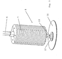
- the Fig. 5 to 7 show a modified embodiment in which the air gap 20 is arranged in a plane, on which the pendulum 6 is perpendicular in a state of rest. Same elements as in the Fig. 1 to 4 are provided with the same reference numerals.
- the circuit board 18 is supported here by a support plate 24.
- the support plate 24 may be formed of steel, for example, whereby a positive influence on the magnetic field is achieved.
- the magnet assembly 12 has a plurality of permanent magnets 16 which are arranged in a plurality of circular rings, here five circular rings. Each annulus is divided into several segments, in this case in eighteen segments. Conveniently, the permanent magnets 16 are always arranged with alternating orientation, so that in a circular ring in the direction of rotation of the annulus always has a permanent magnet with a north pole and the next permanent magnet with a south pole to the conductor assembly 18.
- the permanent magnets in the radial direction are also arranged with alternating polarity, so that a permanent magnet, which is directed with a north pole to the conductor assembly 18, in the radial direction, a permanent magnet follows, which is directed with a south pole to the conductor assembly 18, then again a permanent magnet follows, which is directed with a north pole to the conductor assembly 18.
- the pendulum hinge 13 allows not only an angular change between the pendulum 6 and the magnet assembly 12, but also a certain height offset between the pendulum 6 and the magnet assembly, ie a movement substantially perpendicular to the movement of the pendulum 6.
- the slide assembly 19 defines the distance between the magnet assembly 12 and the conductor assembly 18, so that upon movement of the pendulum 6, the magnet assembly 12 is practically displaced only on the conductor assembly 18.
- the air gap 20 between the magnet assembly 12 and the conductor assembly 18 can thus be kept constant over the entire deflection of the pendulum 6.
- both damper arrangements work in principle in the same way.
- the magnetic field generating device which by the assemblies 12, 22 ( Fig. 2 to 4 ) or the magnet assembly 12 (FIG. Fig. 5 to 7 ) is moved relative to the conductor assembly 18 moves.
- a magnetic field is accordingly moved relative to a conductor, so that eddy currents are induced in the conductor. Since the conductor assembly 18 has no discrete tracks, the eddy currents in this conductor assembly 18 can form freely, regardless of the exact position of the pendulum 6 relative to the conductor assembly 18.
- the energy required to form the eddy currents is removed from the kinetic energy of the pendulum 6 and leads to it to the desired damping.
- a largely temperature-independent damping force can be set.
- a good linearity is obtained, i. a velocity-proportional damping force, regardless of the position or deflection of the pendulum 6.
- the components of the damping assembly 8 operate virtually wear-free, i. The cost of maintenance can be kept extremely small.
- the dimensions of the magnet assemblies 12, 22 or the magnet assembly 12 may be varied. As long as it is ensured that even with the largest deflection of the pendulum 6 there is an overlap between the magnetic field generating device and the conductor arrangement 18, the magnetic assemblies 12, 22 can be enlarged virtually as desired. Another adjustment results from the choice of the material for the conductor arrangement and by the choice of the geometric dimensions, in particular the thickness of the conductor arrangement and the air gap.
- the heat generated by the eddy currents can be dissipated via the surface of the conductor assembly 18 easily.
Landscapes
- Engineering & Computer Science (AREA)
- General Engineering & Computer Science (AREA)
- Mechanical Engineering (AREA)
- Sustainable Energy (AREA)
- Chemical & Material Sciences (AREA)
- Combustion & Propulsion (AREA)
- Life Sciences & Earth Sciences (AREA)
- Sustainable Development (AREA)
- Physics & Mathematics (AREA)
- Electromagnetism (AREA)
- Acoustics & Sound (AREA)
- Aviation & Aerospace Engineering (AREA)
- Vibration Prevention Devices (AREA)
Claims (15)
- Agencement d'amortissement d'oscillations destiné à la réduction des oscillations pour des bâtiments (2) minces et hauts, avec un pendule (6) qui peut être suspendu au bâtiment (2) et présente une masse d'amortissement (7), et un ensemble amortisseur (8), caractérisé en ce que l'ensemble amortisseur (8) est réalisé comme un amortisseur à courant de Foucault, l'amortisseur à courant de Foucault présentant deux éléments, dont un est réalisé comme un dispositif de génération de champ magnétique (12, 22) et l'autre est réalisé comme un agencement conducteur (18), l'un des éléments pouvant être déplacé par rapport à l'autre par un mouvement du pendule (6), et un agencement glissant (19) étant agencé entre les deux éléments.
- Agencement d'amortissement d'oscillations selon la revendication 1, caractérisé en ce que l'agencement conducteur présente une plaque conductrice qui est agencée parallèlement à la direction du mouvement du pendule (6).
- Agencement d'amortissement d'oscillations selon la revendication 2, caractérisé en ce que la plaque est en aluminium ou en cuivre ou en un alliage d'aluminium et de cuivre ou en un autre matériau présentant une conductivité électrique élevée.
- Agencement d'amortissement d'oscillations selon l'une quelconque des revendications 1 à 3, caractérisé en ce que l'agencement conducteur (18) est soutenu par une plaque porteuse (24).
- Agencement d'amortissement d'oscillations selon l'une quelconque des revendications 1 à 4, caractérisé en ce que l'un des éléments est relié par une liaison pendule-articulation (13) au pendule (6).
- Agencement d'amortissement d'oscillations selon la revendication 5, caractérisé en ce que la liaison pendule-articulation (13) permet un mouvement entre le pendule (6) et l'élément perpendiculairement à la direction du mouvement du pendule (6).
- Agencement d'amortissement d'oscillations selon la revendication 5 ou 6, caractérisé en ce que l'autre des éléments peut être relié par une liaison bâtiment-articulation (23) au bâtiment (2).
- Agencement d'amortissement d'oscillations selon l'une quelconque des revendications 5 à 7, caractérisé en ce que les deux éléments sont couplés ensemble par un guidage parallèle.
- Agencement d'amortissement d'oscillations selon la revendication 7, caractérisé en ce que l'un des éléments est réalisé avec deux parties (14, 15) et l'autre élément est agencé entre les deux parties (14, 15).
- Agencement d'amortissement d'oscillations selon l'une quelconque des revendications 1 à 9, caractérisé en ce qu'une fente d'air (20, 21) est réalisée entre les deux éléments, laquelle est agencée parallèlement à un plan, dans lequel le pendule (6) se trouve dans un état de repos.
- Agencement d'amortissement d'oscillations selon l'une quelconque des revendications 1 à 9, caractérisé en ce qu'une fente d'air (20) est réalisée entre les deux éléments, laquelle est agencée parallèlement à un plan, sur lequel le pendule (6) se trouve perpendiculaire à l'état de repos.
- Agencement d'amortissement d'oscillations selon l'une quelconque des revendications 1 à 11, caractérisé en ce que l'amortisseur à courant de Foucault est agencé sur l'extrémité inférieure du pendule (6) dans le sens de la force de gravité.
- Agencement d'amortissement d'oscillations selon l'une quelconque des revendications 1 à 12, caractérisé en ce que la masse d'amortissement (7) est agencée de manière réglable en hauteur sur le pendule (6).
- Agencement d'amortissement d'oscillations selon l'une quelconque des revendications 1 à 13, caractérisé en ce que le pendule (6) est relié à un agencement à ressort (10) qui peut être positionné entre le pendule (6) et le bâtiment (2).
- Bâtiment (2) avec un agencement d'amortissement d'oscillations selon l'une quelconque des revendications 1 à 12.
Priority Applications (2)
| Application Number | Priority Date | Filing Date | Title |
|---|---|---|---|
| DK12005805.2T DK2696072T3 (en) | 2012-08-10 | 2012-08-10 | Vibration absorber for wind power plants with a lot of pendulum and hvirvelstrømsdæmper |
| EP12005805.2A EP2696072B1 (fr) | 2012-08-10 | 2012-08-10 | Agencement de réduction de vibrations, en particulier pour les constructions hautes et fines, et construction dotée d'un agencement de réduction de vibrations |
Applications Claiming Priority (1)
| Application Number | Priority Date | Filing Date | Title |
|---|---|---|---|
| EP12005805.2A EP2696072B1 (fr) | 2012-08-10 | 2012-08-10 | Agencement de réduction de vibrations, en particulier pour les constructions hautes et fines, et construction dotée d'un agencement de réduction de vibrations |
Publications (2)
| Publication Number | Publication Date |
|---|---|
| EP2696072A1 EP2696072A1 (fr) | 2014-02-12 |
| EP2696072B1 true EP2696072B1 (fr) | 2015-03-25 |
Family
ID=46967894
Family Applications (1)
| Application Number | Title | Priority Date | Filing Date |
|---|---|---|---|
| EP12005805.2A Active EP2696072B1 (fr) | 2012-08-10 | 2012-08-10 | Agencement de réduction de vibrations, en particulier pour les constructions hautes et fines, et construction dotée d'un agencement de réduction de vibrations |
Country Status (2)
| Country | Link |
|---|---|
| EP (1) | EP2696072B1 (fr) |
| DK (1) | DK2696072T3 (fr) |
Cited By (3)
| Publication number | Priority date | Publication date | Assignee | Title |
|---|---|---|---|---|
| CN111164326A (zh) * | 2017-08-08 | 2020-05-15 | Fm能源有限责任两合公司 | 旋转阻尼器和装备有旋转阻尼器的振动减振器 |
| EP3441609B1 (fr) * | 2017-08-09 | 2023-05-10 | General Electric Company | Dispositif d'amortissement pour éoliennes à terre et en mer |
| US12607246B2 (en) | 2021-03-31 | 2026-04-21 | Fm Energie Gmbh & Co.Kg | Temperature-adaptive eddy current rotation damper |
Families Citing this family (10)
| Publication number | Priority date | Publication date | Assignee | Title |
|---|---|---|---|---|
| PT3180542T (pt) | 2014-08-13 | 2019-01-11 | Esm Energie Und Schwingungstechnik Mitsch Gmbh | Amortecedor magnético para absorção de vibrações |
| EP3388709B1 (fr) * | 2017-04-13 | 2021-01-06 | Wölfel Engineering GmbH & Co. KG. | Système d'amortissement de vibrations |
| WO2019185196A1 (fr) | 2018-03-30 | 2019-10-03 | Esm Energie- Und Schwingungstechnik Mitsch Gmbh | Ressort magnetique linéaire et utilisation dans des amortisseurs de vibrations |
| EP3781837A1 (fr) | 2018-04-18 | 2021-02-24 | FM Energie GmbH & Co. KG | Suspension cardan à amortissement pour amortisseur de vibrations |
| EP3575630B1 (fr) * | 2018-05-29 | 2021-05-12 | Wölfel Engineering GmbH + Co. KG | Système d'amortissement de vibrations |
| EP3814628B1 (fr) | 2018-06-29 | 2023-08-02 | Vestas Wind Systems A/S | Unité d'amortissement pour structure de tour |
| WO2020077595A1 (fr) * | 2018-10-18 | 2020-04-23 | 大连理工大学 | Amortisseur de masse accordé par courants de foucault électriques multidimensionnel |
| CN113464384A (zh) * | 2020-03-31 | 2021-10-01 | 北京金风科创风电设备有限公司 | 阻尼装置及风力发电机组 |
| EP4086459A1 (fr) | 2021-05-06 | 2022-11-09 | General Electric Renovables España S.L. | Éolienne dotée d'un modificateur de fréquence propre |
| CN115405648B (zh) * | 2022-08-03 | 2025-04-29 | 上海电气风电集团股份有限公司 | 单摆式减振装置及风力发电机组 |
Citations (5)
| Publication number | Priority date | Publication date | Assignee | Title |
|---|---|---|---|---|
| SU853034A2 (ru) | 1979-05-10 | 1981-08-07 | Харьковское Отделение Всесоюзногогосударственного Ордена Ленина Иордена Октябрьской Революциипроектного Института "Теплоэлектро-Проект" | Динамический гаситель колебанийСООРужЕНи |
| EP0767321A2 (fr) | 1995-10-02 | 1997-04-09 | Kabushiki Kaisha Toshiba | Amortisseur dynamique de vibrations |
| WO2009068599A2 (fr) | 2007-11-28 | 2009-06-04 | Vestas Wind Systems A/S | Procédé pour amortir des oscillations dans une éolienne |
| CN202091424U (zh) | 2011-06-13 | 2011-12-28 | 马人乐 | 风力发电塔钟式减振器 |
| WO2012061859A2 (fr) | 2010-11-10 | 2012-05-18 | Alois Penz | Structure creuse de type tour, en particulier cheminée à courant d'air ascendant |
Family Cites Families (4)
| Publication number | Priority date | Publication date | Assignee | Title |
|---|---|---|---|---|
| JPS63149446A (ja) * | 1986-12-11 | 1988-06-22 | Bridgestone Corp | 防振装置 |
| JPH01108431A (ja) * | 1987-10-22 | 1989-04-25 | Toshiba Corp | 磁気ダンパ装置 |
| DE19856500B4 (de) | 1998-12-08 | 2005-12-08 | Franz Mitsch | Schwingungstilger |
| US20070131504A1 (en) * | 2005-12-14 | 2007-06-14 | Northrop Grumman Corporation | Planar vibration absorber |
-
2012
- 2012-08-10 EP EP12005805.2A patent/EP2696072B1/fr active Active
- 2012-08-10 DK DK12005805.2T patent/DK2696072T3/en active
Patent Citations (5)
| Publication number | Priority date | Publication date | Assignee | Title |
|---|---|---|---|---|
| SU853034A2 (ru) | 1979-05-10 | 1981-08-07 | Харьковское Отделение Всесоюзногогосударственного Ордена Ленина Иордена Октябрьской Революциипроектного Института "Теплоэлектро-Проект" | Динамический гаситель колебанийСООРужЕНи |
| EP0767321A2 (fr) | 1995-10-02 | 1997-04-09 | Kabushiki Kaisha Toshiba | Amortisseur dynamique de vibrations |
| WO2009068599A2 (fr) | 2007-11-28 | 2009-06-04 | Vestas Wind Systems A/S | Procédé pour amortir des oscillations dans une éolienne |
| WO2012061859A2 (fr) | 2010-11-10 | 2012-05-18 | Alois Penz | Structure creuse de type tour, en particulier cheminée à courant d'air ascendant |
| CN202091424U (zh) | 2011-06-13 | 2011-12-28 | 马人乐 | 风力发电塔钟式减振器 |
Non-Patent Citations (7)
| Title |
|---|
| CHRISTIAN PETERSEN: "Dynamik der Baukonstruktionen", 1996, VIEWEG, ISBN: 3-528-08123-6, article "Schwingungsdämpfer", pages: 821-850, 1003 - 1011, XP055316331 |
| EBRAHIMI ET AL.: "Design and modeling of a magnetic shock absorber base on eddy current damping effect", JOURNAL OF SOUND AND VIBRATION, vol. 315, 2008, pages 875 - 889, XP022705855 |
| KOBAYASHI ET AL.: "Houde Damper Using Magnet Damping and its Application to the Piping system", SEISMIC ENGINEERING, vol. 2, 1994, pages 105 - 109, XP055316418 |
| R. PALOMERA-ARIAS ET AL.: "Feasibility Study of Passive Electromagnetic Damping Systems", JOURNAL OF STRUCTURAL ENGINEERING, ASCE, vol. 134, no. 1, January 2008 (2008-01-01), pages 164 - 170, XP055316420 |
| TAICHI MATSUOKA ET AL.: "A Study of a Magnetic Damper Using Rare-Earth Magnets and a Pinned Displacement Magnifying Mechanism", INTERNATIONAL JOURNAL OF APPLIED ELECTROMAGNETICS AND MECHANICS, vol. 13, no. 1-4, 2001, pages 261 - 270, XP055316410 |
| VEREIN DEUTSCHER INGENIEURE (VDI): "VDI Richtlinie 3833 Blatt 2 - Schwingungsdämpfer und Schwingungstilger", VDI-RICHTLINIEN, December 2006 (2006-12-01), pages 1 - 36, XP055316440 |
| ZUO ET AL.: "Design and Analysis of a New Type of Electromagnetic Damper With increased Energy Density", JOURNAL OF VIBRATION AND ACOUSTICS, vol. 133, August 2011 (2011-08-01), pages 041006-1 - 041006-8, XP055316426 |
Cited By (4)
| Publication number | Priority date | Publication date | Assignee | Title |
|---|---|---|---|---|
| CN111164326A (zh) * | 2017-08-08 | 2020-05-15 | Fm能源有限责任两合公司 | 旋转阻尼器和装备有旋转阻尼器的振动减振器 |
| CN111164326B (zh) * | 2017-08-08 | 2022-02-22 | Fm能源有限责任两合公司 | 旋转阻尼器和装备有旋转阻尼器的振动减振器 |
| EP3441609B1 (fr) * | 2017-08-09 | 2023-05-10 | General Electric Company | Dispositif d'amortissement pour éoliennes à terre et en mer |
| US12607246B2 (en) | 2021-03-31 | 2026-04-21 | Fm Energie Gmbh & Co.Kg | Temperature-adaptive eddy current rotation damper |
Also Published As
| Publication number | Publication date |
|---|---|
| EP2696072A1 (fr) | 2014-02-12 |
| DK2696072T3 (en) | 2015-06-08 |
Similar Documents
| Publication | Publication Date | Title |
|---|---|---|
| EP2696072B1 (fr) | Agencement de réduction de vibrations, en particulier pour les constructions hautes et fines, et construction dotée d'un agencement de réduction de vibrations | |
| EP2746483B1 (fr) | Dispositif d'amortisseur d'oscillations | |
| EP1008747B1 (fr) | Amortisseur de vibration pour éoliennes | |
| EP2929098B1 (fr) | Module et dispositif de limitation des vibrations, segment de construction pour un dispositif de construction et éolienne équipée d'un module de limitation des vibrations | |
| EP3227579B1 (fr) | Amortisseur de vibrations adaptatif muni d'un système de ressort | |
| WO2019029839A1 (fr) | Dispositif d'amortisseement en rotation et amortisseur de vibrations equipé d'un tel dispositif | |
| WO2018189245A1 (fr) | Amortissement des vibrations d'une tour de centrale éolienne | |
| WO2019201471A1 (fr) | Suspension cardan à amortissement pour amortisseur de vibrations | |
| DE102008042478A1 (de) | Verfahren zur Schwingungstilgung und horizontal wirkender Schwingungstilger | |
| DE102006022266A1 (de) | Windenergieanlage | |
| DE102007041128B4 (de) | Schwinggenerator | |
| EP3433509B1 (fr) | Pendule d'amortissement tridimensionnel compact avec trajectoire ellïpsoidale | |
| DE102010006544A1 (de) | Rotorblatt für eine Windenergieanlage und Verfahren zur Dämpfung von Schwingungen eines Rotorblatts | |
| DE102011101271A1 (de) | Turmschwingungstilger und Turm mit einem Turmschwingungstilger | |
| DE202011001901U1 (de) | Vorrichtung zur Schwingungsanregung von Rotorblättern im Rahmen von Schwingungstests | |
| EP4244502A1 (fr) | Amortisseur de bâtiments permettant de protéger des bâtiments contre des vibrations et bâtiment comprenant un tel amortisseur de bâtiments | |
| WO2019185196A1 (fr) | Ressort magnetique linéaire et utilisation dans des amortisseurs de vibrations | |
| DE19715714A1 (de) | Dämpferelement und damit versehene Dämpfungseinheit | |
| EP2730709A1 (fr) | Agencement de réduction de vibrations | |
| EP3575630B1 (fr) | Système d'amortissement de vibrations | |
| EP2715248A2 (fr) | Dispositifs d'optimisation et de stabilisation de fonctionnement de modules/modules de capteurs solaires et de groupes modulaires de capteurs assemblés envers des sollicitations de l'environnement, notamment le vent et les particules et objets transportés par le vent | |
| EP2730799A1 (fr) | Agencement de réduction de vibrations pour la réduction des vibrations | |
| WO2026052602A1 (fr) | Ensemble amortisseur à masse accordée pour structures hautes et minces | |
| EP3976990B1 (fr) | Amortisseur d'impulsion pour constructions et installations minces et hautes | |
| DE102006013333A1 (de) | Verfahren und Vorrichtung zur Energiegewinnung |
Legal Events
| Date | Code | Title | Description |
|---|---|---|---|
| AK | Designated contracting states |
Kind code of ref document: A1 Designated state(s): AL AT BE BG CH CY CZ DE DK EE ES FI FR GB GR HR HU IE IS IT LI LT LU LV MC MK MT NL NO PL PT RO RS SE SI SK SM TR |
|
| AX | Request for extension of the european patent |
Extension state: BA ME |
|
| PUAI | Public reference made under article 153(3) epc to a published international application that has entered the european phase |
Free format text: ORIGINAL CODE: 0009012 |
|
| 17P | Request for examination filed |
Effective date: 20140116 |
|
| RBV | Designated contracting states (corrected) |
Designated state(s): AL AT BE BG CH CY CZ DE DK EE ES FI FR GB GR HR HU IE IS IT LI LT LU LV MC MK MT NL NO PL PT RO RS SE SI SK SM TR |
|
| GRAP | Despatch of communication of intention to grant a patent |
Free format text: ORIGINAL CODE: EPIDOSNIGR1 |
|
| RIC1 | Information provided on ipc code assigned before grant |
Ipc: F03D 11/04 20060101ALI20141007BHEP Ipc: F03D 11/00 20060101AFI20141007BHEP Ipc: F16F 15/03 20060101ALI20141007BHEP |
|
| INTG | Intention to grant announced |
Effective date: 20141103 |
|
| GRAS | Grant fee paid |
Free format text: ORIGINAL CODE: EPIDOSNIGR3 |
|
| GRAA | (expected) grant |
Free format text: ORIGINAL CODE: 0009210 |
|
| AK | Designated contracting states |
Kind code of ref document: B1 Designated state(s): AL AT BE BG CH CY CZ DE DK EE ES FI FR GB GR HR HU IE IS IT LI LT LU LV MC MK MT NL NO PL PT RO RS SE SI SK SM TR |
|
| REG | Reference to a national code |
Ref country code: GB Ref legal event code: FG4D Free format text: NOT ENGLISH |
|
| REG | Reference to a national code |
Ref country code: CH Ref legal event code: EP |
|
| REG | Reference to a national code |
Ref country code: IE Ref legal event code: FG4D Free format text: LANGUAGE OF EP DOCUMENT: GERMAN |
|
| REG | Reference to a national code |
Ref country code: DE Ref legal event code: R096 Ref document number: 502012002610 Country of ref document: DE Effective date: 20150507 |
|
| REG | Reference to a national code |
Ref country code: AT Ref legal event code: REF Ref document number: 718053 Country of ref document: AT Kind code of ref document: T Effective date: 20150515 |
|
| REG | Reference to a national code |
Ref country code: DK Ref legal event code: T3 Effective date: 20150604 |
|
| REG | Reference to a national code |
Ref country code: SE Ref legal event code: TRGR |
|
| PG25 | Lapsed in a contracting state [announced via postgrant information from national office to epo] |
Ref country code: FI Free format text: LAPSE BECAUSE OF FAILURE TO SUBMIT A TRANSLATION OF THE DESCRIPTION OR TO PAY THE FEE WITHIN THE PRESCRIBED TIME-LIMIT Effective date: 20150325 Ref country code: LT Free format text: LAPSE BECAUSE OF FAILURE TO SUBMIT A TRANSLATION OF THE DESCRIPTION OR TO PAY THE FEE WITHIN THE PRESCRIBED TIME-LIMIT Effective date: 20150325 Ref country code: HR Free format text: LAPSE BECAUSE OF FAILURE TO SUBMIT A TRANSLATION OF THE DESCRIPTION OR TO PAY THE FEE WITHIN THE PRESCRIBED TIME-LIMIT Effective date: 20150325 |
|
| REG | Reference to a national code |
Ref country code: FR Ref legal event code: PLFP Year of fee payment: 4 |
|
| REG | Reference to a national code |
Ref country code: LT Ref legal event code: MG4D |
|
| PG25 | Lapsed in a contracting state [announced via postgrant information from national office to epo] |
Ref country code: LV Free format text: LAPSE BECAUSE OF FAILURE TO SUBMIT A TRANSLATION OF THE DESCRIPTION OR TO PAY THE FEE WITHIN THE PRESCRIBED TIME-LIMIT Effective date: 20150325 Ref country code: GR Free format text: LAPSE BECAUSE OF FAILURE TO SUBMIT A TRANSLATION OF THE DESCRIPTION OR TO PAY THE FEE WITHIN THE PRESCRIBED TIME-LIMIT Effective date: 20150626 Ref country code: RS Free format text: LAPSE BECAUSE OF FAILURE TO SUBMIT A TRANSLATION OF THE DESCRIPTION OR TO PAY THE FEE WITHIN THE PRESCRIBED TIME-LIMIT Effective date: 20150325 |
|
| PG25 | Lapsed in a contracting state [announced via postgrant information from national office to epo] |
Ref country code: NL Free format text: LAPSE BECAUSE OF FAILURE TO SUBMIT A TRANSLATION OF THE DESCRIPTION OR TO PAY THE FEE WITHIN THE PRESCRIBED TIME-LIMIT Effective date: 20150325 |
|
| PG25 | Lapsed in a contracting state [announced via postgrant information from national office to epo] |
Ref country code: CZ Free format text: LAPSE BECAUSE OF FAILURE TO SUBMIT A TRANSLATION OF THE DESCRIPTION OR TO PAY THE FEE WITHIN THE PRESCRIBED TIME-LIMIT Effective date: 20150325 Ref country code: SK Free format text: LAPSE BECAUSE OF FAILURE TO SUBMIT A TRANSLATION OF THE DESCRIPTION OR TO PAY THE FEE WITHIN THE PRESCRIBED TIME-LIMIT Effective date: 20150325 Ref country code: RO Free format text: LAPSE BECAUSE OF FAILURE TO SUBMIT A TRANSLATION OF THE DESCRIPTION OR TO PAY THE FEE WITHIN THE PRESCRIBED TIME-LIMIT Effective date: 20150325 Ref country code: ES Free format text: LAPSE BECAUSE OF FAILURE TO SUBMIT A TRANSLATION OF THE DESCRIPTION OR TO PAY THE FEE WITHIN THE PRESCRIBED TIME-LIMIT Effective date: 20150325 Ref country code: EE Free format text: LAPSE BECAUSE OF FAILURE TO SUBMIT A TRANSLATION OF THE DESCRIPTION OR TO PAY THE FEE WITHIN THE PRESCRIBED TIME-LIMIT Effective date: 20150325 Ref country code: PT Free format text: LAPSE BECAUSE OF FAILURE TO SUBMIT A TRANSLATION OF THE DESCRIPTION OR TO PAY THE FEE WITHIN THE PRESCRIBED TIME-LIMIT Effective date: 20150727 |
|
| PG25 | Lapsed in a contracting state [announced via postgrant information from national office to epo] |
Ref country code: PL Free format text: LAPSE BECAUSE OF FAILURE TO SUBMIT A TRANSLATION OF THE DESCRIPTION OR TO PAY THE FEE WITHIN THE PRESCRIBED TIME-LIMIT Effective date: 20150325 Ref country code: IS Free format text: LAPSE BECAUSE OF FAILURE TO SUBMIT A TRANSLATION OF THE DESCRIPTION OR TO PAY THE FEE WITHIN THE PRESCRIBED TIME-LIMIT Effective date: 20150725 |
|
| REG | Reference to a national code |
Ref country code: DE Ref legal event code: R026 Ref document number: 502012002610 Country of ref document: DE |
|
| PLBI | Opposition filed |
Free format text: ORIGINAL CODE: 0009260 |
|
| PLBI | Opposition filed |
Free format text: ORIGINAL CODE: 0009260 |
|
| 26 | Opposition filed |
Opponent name: ESM ENERGIE- UND SCHWINGUNGSTECHNIK MITSCH GMBH Effective date: 20151219 |
|
| PLAX | Notice of opposition and request to file observation + time limit sent |
Free format text: ORIGINAL CODE: EPIDOSNOBS2 |
|
| 26 | Opposition filed |
Opponent name: SIEMENS AKTIENGESELLSCHAFT Effective date: 20151223 |
|
| PG25 | Lapsed in a contracting state [announced via postgrant information from national office to epo] |
Ref country code: MC Free format text: LAPSE BECAUSE OF FAILURE TO SUBMIT A TRANSLATION OF THE DESCRIPTION OR TO PAY THE FEE WITHIN THE PRESCRIBED TIME-LIMIT Effective date: 20150325 Ref country code: LU Free format text: LAPSE BECAUSE OF FAILURE TO SUBMIT A TRANSLATION OF THE DESCRIPTION OR TO PAY THE FEE WITHIN THE PRESCRIBED TIME-LIMIT Effective date: 20150810 |
|
| REG | Reference to a national code |
Ref country code: CH Ref legal event code: PL |
|
| PG25 | Lapsed in a contracting state [announced via postgrant information from national office to epo] |
Ref country code: CH Free format text: LAPSE BECAUSE OF NON-PAYMENT OF DUE FEES Effective date: 20150831 Ref country code: LI Free format text: LAPSE BECAUSE OF NON-PAYMENT OF DUE FEES Effective date: 20150831 Ref country code: IT Free format text: LAPSE BECAUSE OF FAILURE TO SUBMIT A TRANSLATION OF THE DESCRIPTION OR TO PAY THE FEE WITHIN THE PRESCRIBED TIME-LIMIT Effective date: 20150325 |
|
| PG25 | Lapsed in a contracting state [announced via postgrant information from national office to epo] |
Ref country code: SI Free format text: LAPSE BECAUSE OF FAILURE TO SUBMIT A TRANSLATION OF THE DESCRIPTION OR TO PAY THE FEE WITHIN THE PRESCRIBED TIME-LIMIT Effective date: 20150325 |
|
| REG | Reference to a national code |
Ref country code: IE Ref legal event code: MM4A |
|
| PLAF | Information modified related to communication of a notice of opposition and request to file observations + time limit |
Free format text: ORIGINAL CODE: EPIDOSCOBS2 |
|
| PG25 | Lapsed in a contracting state [announced via postgrant information from national office to epo] |
Ref country code: IE Free format text: LAPSE BECAUSE OF NON-PAYMENT OF DUE FEES Effective date: 20150810 |
|
| PLBB | Reply of patent proprietor to notice(s) of opposition received |
Free format text: ORIGINAL CODE: EPIDOSNOBS3 |
|
| REG | Reference to a national code |
Ref country code: FR Ref legal event code: PLFP Year of fee payment: 5 |
|
| PG25 | Lapsed in a contracting state [announced via postgrant information from national office to epo] |
Ref country code: MT Free format text: LAPSE BECAUSE OF FAILURE TO SUBMIT A TRANSLATION OF THE DESCRIPTION OR TO PAY THE FEE WITHIN THE PRESCRIBED TIME-LIMIT Effective date: 20150325 |
|
| PG25 | Lapsed in a contracting state [announced via postgrant information from national office to epo] |
Ref country code: SM Free format text: LAPSE BECAUSE OF FAILURE TO SUBMIT A TRANSLATION OF THE DESCRIPTION OR TO PAY THE FEE WITHIN THE PRESCRIBED TIME-LIMIT Effective date: 20150325 Ref country code: NO Free format text: LAPSE BECAUSE OF FAILURE TO SUBMIT A TRANSLATION OF THE DESCRIPTION OR TO PAY THE FEE WITHIN THE PRESCRIBED TIME-LIMIT Effective date: 20150625 Ref country code: HU Free format text: LAPSE BECAUSE OF FAILURE TO SUBMIT A TRANSLATION OF THE DESCRIPTION OR TO PAY THE FEE WITHIN THE PRESCRIBED TIME-LIMIT; INVALID AB INITIO Effective date: 20120810 Ref country code: BG Free format text: LAPSE BECAUSE OF FAILURE TO SUBMIT A TRANSLATION OF THE DESCRIPTION OR TO PAY THE FEE WITHIN THE PRESCRIBED TIME-LIMIT Effective date: 20150325 |
|
| PG25 | Lapsed in a contracting state [announced via postgrant information from national office to epo] |
Ref country code: CY Free format text: LAPSE BECAUSE OF FAILURE TO SUBMIT A TRANSLATION OF THE DESCRIPTION OR TO PAY THE FEE WITHIN THE PRESCRIBED TIME-LIMIT Effective date: 20150325 |
|
| PG25 | Lapsed in a contracting state [announced via postgrant information from national office to epo] |
Ref country code: BE Free format text: LAPSE BECAUSE OF NON-PAYMENT OF DUE FEES Effective date: 20150831 |
|
| REG | Reference to a national code |
Ref country code: FR Ref legal event code: PLFP Year of fee payment: 6 |
|
| PLBP | Opposition withdrawn |
Free format text: ORIGINAL CODE: 0009264 |
|
| REG | Reference to a national code |
Ref country code: DE Ref legal event code: R100 Ref document number: 502012002610 Country of ref document: DE |
|
| PLBP | Opposition withdrawn |
Free format text: ORIGINAL CODE: 0009264 |
|
| PLCK | Communication despatched that opposition was rejected |
Free format text: ORIGINAL CODE: EPIDOSNREJ1 |
|
| PLAB | Opposition data, opponent's data or that of the opponent's representative modified |
Free format text: ORIGINAL CODE: 0009299OPPO |
|
| PLBN | Opposition rejected |
Free format text: ORIGINAL CODE: 0009273 |
|
| STAA | Information on the status of an ep patent application or granted ep patent |
Free format text: STATUS: OPPOSITION REJECTED |
|
| 27O | Opposition rejected |
Effective date: 20170913 |
|
| PG25 | Lapsed in a contracting state [announced via postgrant information from national office to epo] |
Ref country code: MK Free format text: LAPSE BECAUSE OF FAILURE TO SUBMIT A TRANSLATION OF THE DESCRIPTION OR TO PAY THE FEE WITHIN THE PRESCRIBED TIME-LIMIT Effective date: 20150325 Ref country code: TR Free format text: LAPSE BECAUSE OF FAILURE TO SUBMIT A TRANSLATION OF THE DESCRIPTION OR TO PAY THE FEE WITHIN THE PRESCRIBED TIME-LIMIT Effective date: 20150325 |
|
| REG | Reference to a national code |
Ref country code: FR Ref legal event code: PLFP Year of fee payment: 7 |
|
| REG | Reference to a national code |
Ref country code: AT Ref legal event code: MM01 Ref document number: 718053 Country of ref document: AT Kind code of ref document: T Effective date: 20170810 |
|
| REG | Reference to a national code |
Ref country code: DE Ref legal event code: R082 Ref document number: 502012002610 Country of ref document: DE Representative=s name: KEIL & SCHAAFHAUSEN PATENTANWAELTE PARTGMBB, DE Ref country code: DE Ref legal event code: R082 Ref document number: 502012002610 Country of ref document: DE Representative=s name: KEIL & SCHAAFHAUSEN PATENT- UND RECHTSANWAELTE, DE |
|
| PG25 | Lapsed in a contracting state [announced via postgrant information from national office to epo] |
Ref country code: AL Free format text: LAPSE BECAUSE OF FAILURE TO SUBMIT A TRANSLATION OF THE DESCRIPTION OR TO PAY THE FEE WITHIN THE PRESCRIBED TIME-LIMIT Effective date: 20150325 |
|
| PG25 | Lapsed in a contracting state [announced via postgrant information from national office to epo] |
Ref country code: AT Free format text: LAPSE BECAUSE OF NON-PAYMENT OF DUE FEES Effective date: 20170810 |
|
| P01 | Opt-out of the competence of the unified patent court (upc) registered |
Effective date: 20230524 |
|
| PGFP | Annual fee paid to national office [announced via postgrant information from national office to epo] |
Ref country code: DK Payment date: 20250821 Year of fee payment: 14 Ref country code: DE Payment date: 20250822 Year of fee payment: 14 |
|
| PGFP | Annual fee paid to national office [announced via postgrant information from national office to epo] |
Ref country code: GB Payment date: 20250822 Year of fee payment: 14 |
|
| PGFP | Annual fee paid to national office [announced via postgrant information from national office to epo] |
Ref country code: FR Payment date: 20250821 Year of fee payment: 14 |
|
| PGFP | Annual fee paid to national office [announced via postgrant information from national office to epo] |
Ref country code: SE Payment date: 20250821 Year of fee payment: 14 |