EP2696080B1 - Elektrohydrauliksteuerung - Google Patents
Elektrohydrauliksteuerung Download PDFInfo
- Publication number
- EP2696080B1 EP2696080B1 EP12179874.8A EP12179874A EP2696080B1 EP 2696080 B1 EP2696080 B1 EP 2696080B1 EP 12179874 A EP12179874 A EP 12179874A EP 2696080 B1 EP2696080 B1 EP 2696080B1
- Authority
- EP
- European Patent Office
- Prior art keywords
- valve
- pilot pressure
- control
- proportional
- valves
- Prior art date
- Legal status (The legal status is an assumption and is not a legal conclusion. Google has not performed a legal analysis and makes no representation as to the accuracy of the status listed.)
- Not-in-force
Links
- 230000001105 regulatory effect Effects 0.000 claims description 8
- 230000007704 transition Effects 0.000 claims description 8
- 230000000903 blocking effect Effects 0.000 claims description 7
- 230000001944 accentuation Effects 0.000 claims 1
- 238000013016 damping Methods 0.000 description 56
- 238000010586 diagram Methods 0.000 description 11
- 230000001276 controlling effect Effects 0.000 description 7
- 230000009191 jumping Effects 0.000 description 4
- 230000002441 reversible effect Effects 0.000 description 3
- 238000011144 upstream manufacturing Methods 0.000 description 3
- 230000000694 effects Effects 0.000 description 2
- 230000003370 grooming effect Effects 0.000 description 2
- 230000035939 shock Effects 0.000 description 2
- 239000000654 additive Substances 0.000 description 1
- 230000000996 additive effect Effects 0.000 description 1
- 230000002238 attenuated effect Effects 0.000 description 1
- 230000015572 biosynthetic process Effects 0.000 description 1
- 230000006735 deficit Effects 0.000 description 1
- 230000003111 delayed effect Effects 0.000 description 1
- 230000001419 dependent effect Effects 0.000 description 1
- 230000006866 deterioration Effects 0.000 description 1
- 239000012530 fluid Substances 0.000 description 1
- ZZUFCTLCJUWOSV-UHFFFAOYSA-N furosemide Chemical compound C1=C(Cl)C(S(=O)(=O)N)=CC(C(O)=O)=C1NCC1=CC=CO1 ZZUFCTLCJUWOSV-UHFFFAOYSA-N 0.000 description 1
- 230000000670 limiting effect Effects 0.000 description 1
- 238000012423 maintenance Methods 0.000 description 1
- 230000002829 reductive effect Effects 0.000 description 1
- 230000000284 resting effect Effects 0.000 description 1
- 230000000979 retarding effect Effects 0.000 description 1
- 238000003971 tillage Methods 0.000 description 1
Images




Classifications
-
- F—MECHANICAL ENGINEERING; LIGHTING; HEATING; WEAPONS; BLASTING
- F15—FLUID-PRESSURE ACTUATORS; HYDRAULICS OR PNEUMATICS IN GENERAL
- F15B—SYSTEMS ACTING BY MEANS OF FLUIDS IN GENERAL; FLUID-PRESSURE ACTUATORS, e.g. SERVOMOTORS; DETAILS OF FLUID-PRESSURE SYSTEMS, NOT OTHERWISE PROVIDED FOR
- F15B11/00—Servomotor systems without provision for follow-up action; Circuits therefor
- F15B11/003—Systems with load-holding valves
-
- F—MECHANICAL ENGINEERING; LIGHTING; HEATING; WEAPONS; BLASTING
- F15—FLUID-PRESSURE ACTUATORS; HYDRAULICS OR PNEUMATICS IN GENERAL
- F15B—SYSTEMS ACTING BY MEANS OF FLUIDS IN GENERAL; FLUID-PRESSURE ACTUATORS, e.g. SERVOMOTORS; DETAILS OF FLUID-PRESSURE SYSTEMS, NOT OTHERWISE PROVIDED FOR
- F15B2211/00—Circuits for servomotor systems
- F15B2211/30—Directional control
- F15B2211/31—Directional control characterised by the positions of the valve element
- F15B2211/3122—Special positions other than the pump port being connected to working ports or the working ports being connected to the return line
- F15B2211/3127—Floating position connecting the working ports and the return line
-
- F—MECHANICAL ENGINEERING; LIGHTING; HEATING; WEAPONS; BLASTING
- F15—FLUID-PRESSURE ACTUATORS; HYDRAULICS OR PNEUMATICS IN GENERAL
- F15B—SYSTEMS ACTING BY MEANS OF FLUIDS IN GENERAL; FLUID-PRESSURE ACTUATORS, e.g. SERVOMOTORS; DETAILS OF FLUID-PRESSURE SYSTEMS, NOT OTHERWISE PROVIDED FOR
- F15B2211/00—Circuits for servomotor systems
- F15B2211/50—Pressure control
- F15B2211/505—Pressure control characterised by the type of pressure control means
- F15B2211/50563—Pressure control characterised by the type of pressure control means the pressure control means controlling a differential pressure
- F15B2211/50581—Pressure control characterised by the type of pressure control means the pressure control means controlling a differential pressure using counterbalance valves
- F15B2211/5059—Pressure control characterised by the type of pressure control means the pressure control means controlling a differential pressure using counterbalance valves using double counterbalance valves
-
- F—MECHANICAL ENGINEERING; LIGHTING; HEATING; WEAPONS; BLASTING
- F15—FLUID-PRESSURE ACTUATORS; HYDRAULICS OR PNEUMATICS IN GENERAL
- F15B—SYSTEMS ACTING BY MEANS OF FLUIDS IN GENERAL; FLUID-PRESSURE ACTUATORS, e.g. SERVOMOTORS; DETAILS OF FLUID-PRESSURE SYSTEMS, NOT OTHERWISE PROVIDED FOR
- F15B2211/00—Circuits for servomotor systems
- F15B2211/50—Pressure control
- F15B2211/575—Pilot pressure control
Definitions
- the invention relates to an electro-hydraulic control according to the preamble of patent claim 1.
- EP 1 766 246 A or DE 199 19 014 A known electro-hydraulic control is the directional slide a 4/4-Proportionalwegeschieber, in addition to two control positions (eg lifting and lowering) has a zero position in which the hydraulic consumer is hydraulically blocked (both working lines shut off to the return and separated from the pressure source), and a fourth position , in which both working lines are connected to the return (floating position).
- the load-holding valves are opened simultaneously and fully in the floating position or at the transition to the control pressure supply via the 4/4 proportional directional slide.
- an attachment excavated by means of the hydraulic consumer then the attachment to follow in the floating position on the ground resting bumps must first be lowered slowly enough by adjusting the lowering control position of the 4/4-proportional directional slide on the ground before the float position is adjusted. This is then the responsibility of the driver. If the lowering control position is overrun too quickly to lower, then the attachment falls hard on the ground.
- an attachment in the floating position can be excavated when jumping over a survey and made to jump, after which it hits hard on the ground, because just in the floating position both load-holding valves are fully open and the hydraulic consumer has no significant resistance.
- a distinctive bottom elevation bring the attachment to jump and hit, because in a control position of the 4/4-proportional directional slider, for example, a certain contact pressure is set on the ground, since the load-holding valves are fully opened.
- Out EP 2 466 153 A is an electro-hydraulic control is known
- the multi-way multi-position directional slide is a 4/3-proportional valve with pressure pilot controls, in which the floating position without fourth slide position is adjustable in that both pressure piloting their proportional solenoids are energized simultaneously and the same, causing the slide his to return open zero position occupies, and at the same time the pilot pressures are transmitted to the two load-holding valves to control this, so that the working lines are connected via the proportional slide with the return.
- the zero position of the slide also becomes hydraulic blocking of the hydraulic consumer used. Then the two proportional solenoids are not energized, so that there are no pilot pressures and the load-holding valves remain in their shut-off positions and block the working lines.
- valve assembly with locking function
- said valve assembly includes a multi-way proportional position proportional slide a 4/4-proportional valve having a zero position between two control positions (lifting / lowering), in which the working lines of the hydraulic consumer from the pressure source and the return are separated and thus the hydraulic consumer is hydraulically blocked.
- a fourth position is provided as a switching position, which is adjustable from the lowered position, and in which both working lines are separated from the pressure source and connected to the return. To switch from the zero position to the floating position, the lowering position must first be overrun.
- 4/4-Proportionalwegeschieber are structurally very complex and expensive, taking into account that usually up to six or eight hydro consumers can share a common pressure source, so that a correspondingly large number of 4/4-proportional valve is needed.
- the pilot control circuits of the two load-holding valves are protected by blocking valves, each of which is held by the pilot circuit of a load-holding valve by control pressure and parallel thereto by a closing spring in a leak-free shut-off when the load-holding valve must be kept controlled.
- Each check valve is switched by control pressure from a pressure in the control position of the control line in the direction of a passage position to allow the control of the load-holding valve.
- both control lines are pressurized, and thus placed both check valves in their passage positions, so that both load-holding valves are turned on.
- the two, monitored by the slide control lines are each permanently connected via a drain throttle with a return line.
- the discharge throttles have no influence on the opening behavior of the load-holding valves, since they act only on the Auf Kunststoffier the check valves and isolated from the pilot circuit of the load-holding valves.
- Out EP 1 528 264 A1 is a load-lowering control valve with Pilotvor facedung known, wherein a pilot valve element for damping purposes in the pilot circuit, a throttle and a gas pressure accumulator are assigned.
- Out EP 0 464 305 A1 is a hydraulic control device with a 4/3-way slide and arranged in only one working line of a double-acting hydraulic consumer load holding valve known. This load-holding valve is opened from the other working line via a control line containing a hydraulic damping device. A floating position of the hydraulic consumer is not adjustable.
- EP 1 927 759 A1 is a double check valve with a floating function known, which is similar operable as the load-holding valves in the EP 2 466 153 A known electro-hydraulic control.
- the double check valve acts as two load-holding valves in the working lines of the double-acting hydraulic consumer, for the direction and speed control of a 4/3-slide is provided with magnetic actuation. In the open zero position of this 4/3-slide both working lines are isolated from the pressure source and connected to the return. However, as long as the double check valve maintains its blocking positions, the hydraulic consumer remains hydraulically blocked in the zero position of the 4/3 slide. Only when the double check valve is acted upon by control pressure from a control pressure source and hydraulically unlocked, resulting in the zero position, a floating position of the hydraulic consumer. The hydraulic release of the double check valve takes place without any damping.
- the invention has for its object to improve an electro-hydraulic control of the type mentioned in that critical or the desired work result impairing movements of a load controlled by the hydraulic consumer can be avoided. Part of the task is thereby, at least in the floating position comfortable, e.g. automatically to be able to act on load movements.
- the damping device is provided in a 4/3-proportional valve with pressure pilot controls and, for example, "electrical" floating position in the pilot circuit of the load-holding valves. Because to be controlled. However, this type of slide is much cheaper and smaller as a four position proportional slider with separate float position. The floating position is set in the "open" zero position by controlling the load holding valves. There are two options here. Both pressure pilot controls are actuated identically and simultaneously via their proportional solenoids, and the pilot pressure is regulated via the damper device to the control sides of the load-holding valves.
- control pressure from the control pressure supply can be used directly via the retarding damper device to control the load holding valves, for example, when the 4/3-proportional directional slide is in its zero position, which it holds by spring force, the proportional solenoid then not necessarily energized at the same time will need, although the proportional magnets can then participate regulate.
- the incorporated in the pilot control damping device ensures at least on the transition to or from and / or during the occupied floating position that load movements are damped in a predetermined or controllable manner.
- the float position for example, without first having to visit the sink control position can be set or turned off very quickly, a load movement occurring is damped and takes place with a time delay which avoids critical states of motion or impairment of a desired result of work by the hydraulic consumer moving implements excludes.
- the damping device can even be used to exclude undesired load movements in control positions of the 4/3 proportional slider, for example a mounted on the ground with a predetermined contact pressure, when it has to negotiate a prominent ground elevation, and in similar situations.
- certain operations of the hydraulic consumer in the electrohydraulic control can be quickly and directly adjusted, but the design is monitored via the damper to prevent damage or deterioration of work or damage to the attachment.
- the damping is set firmly, it comes in each case in a predetermined manner to the effect in which the load-holding valves are controlled controlled. If you work with variable damping, then the damping can be adapted to the circumstances and adjusted, for example, as needed. This is done for example by pressing a pressure switch or with a program routine of an electronic control, so that an operator does not need to worry about a load moved by the hydraulic consumer, eg under the load itself, is controlled slowly enough.
- the load holding valves is thus assigned an additional throttle function by the damping device.
- At least one nozzle is provided in the pilot circuit.
- the pressurization to Open control of at least one load-holding valve made with a time delay, ie the load-holding valve slowly and / or only partially turned on.
- variable damping is performed proportionally across the damper using the pressures generated in the pressure pilot controls of the 4/3 proportional directional damper. This means that although the damping device monitors the time delay of the pressurization when controlling at least one load-holding valve, but an additional influence is also possible because the proportional magnets in the zero position, although equal to each other but more or less energized. This alternative is useful if the float position (control of the load-holding valves in the zero position) is adjusted by picking up the pressures of the pressure pilot control of the 4/3 proportional directional slide.
- the damping device for the purpose of variable damping between the control pressure supply or the pressure pilot, the return, and the Auf Kunststoffbloblo the load-holding valves, a 3/2-proportional pressure control valve or a 3/2-way black / white solenoid valve, preferably at The load-holding valves side facing away from two shuttle valves and / or at least one check valve pair of two opposing check valves.
- the 3/2-way proportional pressure control valve allows, as needed, a variable attenuationmother horrn.
- the 3/2-way black / white magnetic switching valve allows influencing the damping in the control or Zu Kunststoffung the load-holding valves by this valve from the tapped from the control pressure supply or pressure piloting control pressure pressure fluid to the return leaves and so on the way Delay nozzle acts.
- the delay can be controlled very sensitively variable, for example by reducing the tapped from the control pressure supply or the pressure pilot control pressure on the control side of at least one load-holding valve.
- a, preferably elektroproportionales, throttle valve is provided between the return and connected to the control pressure supply or Druckvor Kunststoffmaschineungen control sides of the load-holding valves, preferably on the side facing away from the load-holding valves of two shuttle valves and / or at least one check valve pair.
- the delay can be modulated via the electro-proportional adjustable throttle valve.
- the electrohydraulic control has a proportional pressure control section to which the working lines of the hydraulic consumer are connected are in addition to the pressure control via the 4/3-proportional valve pressures in the working lines to regulate electro-proportional, similar to a conventional secondary pressure limitation. If the pilot circuit downstream of the pressure control section and this is connected to the return, the pilot circuit or at least a part on a control side of a load-holding valve via the pressure control section to the return can be relieved to vary the damping. This may be expedient in particular in the floating position of the 4/3-proportional directional slide, since then the working lines are depressurized.
- the fixed damping or variable damping is the same for both load-holding valves.
- both to and from the hydraulic consumer flowing pressure medium is throttled to achieve the damping.
- the fixed or variable damping may be different for both load-holding valves, or may be different, or only on a load-holding valve, e.g. used for lowering.
- the fixed or variable damping is brought about the damping device even in at least one control position of the 4/3-proportional slider outside the zero position to action. This can be done for example in a control position in which the hydraulic consumer holds an attachment with a predetermined pressure on the ground, which bumps could cause jumping of the attachment, which is eliminated or minimized by the damping.
- the damping device allows a further improvement of the operating behavior and an effect on load movements.
- the load-holding valves are connected so that in two control positions of the 4/3-proportional valve (eg lifting and lowering) arranged in the one working line load-holding valve from the other working line via a connected to the pilot control line with Jerusalem Grahambar from the working line control pressure is auf mortbar ,
- the control lines to shuttle valves or check valve pairs in the pilot circuit.
- the shuttle valves or check valve pairs ensure that in the control positions, the pressure from the working lines is brought to the control sides, while in the floating position or zero position, the control pressures of the pressure pilot control or the control pressure of the control pressure supply is brought to the respective control side, and the damping device is effective.
- each nozzle is arranged on the control side of the load-holding valve in the pilot circuit, wherein the nozzles are sized the same or different.
- At least one return flow damping system can be provided in the working lines and / or on the control sides of the load-holding valves.
- This backflow-damping system consists for example of a non-return valve blocking in the outflow direction, which is bypassed in a bypass line of a nozzle which throttles in the return flow direction.
- Each load-holding valve is, for example, a bypass valve which can be bypassed by a check valve in the inflow direction to the hydraulic consumer and which is spring-loaded on the supply side upstream of the working line and additionally pressure-controlled on the upstream side from the working line downstream of the check valve and from the pilot circuit.
- the load-holding valve a 2/2-way pressure control valve with integrated check valve (locks in the outflow from the hydraulic consumer), the 2/2-way pressure control valve acted upon by spring force to a backflow blocking position and pressure controlled controlled passage positions from the pilot circuit becomes.
- the electrohydraulic control is expedient part of an electronic hoist control, as is customary on mobile work vehicles, which are equipped with at least one attachment or equippable.
- work vehicles are snow plows, snow grooming vehicles, agricultural machines such as tractors, road maintenance machines, or tillage vehicles.
- the damping device which monitors at least the transition to or from the floating position and / or the floating position to avoid critical movements of an attachment, can be activated either permanently or at the touch of a button.
- the different embodiments of the electro-hydraulic control S in the Fig. 1 to 11 can be part of an electronic hoist control EHR (not shown in detail) Fig. 1 ), as used in different mobile working equipment.
- EHR electronic hoist control
- electrohydraulic controls may find use in other areas of high pressure mobile or stationary hydraulics, useful for at least minimizing critical load movements, without the need for an operator of the electrohydraulic controller to necessarily care.
- An electro-hydraulic control S for example, as part of an electrohydraulic hoist control EHR is supplied by a pressure source in a pressure line 1 and is connected to a return line 2.
- a control pressure supply not shown, is connected to a control pressure line 3, while a further tank line 3 'leads to a tank, for example, the control pressure supply.
- Another control line 4 is connected to a load pressure signal circuit LS.
- the electrohydraulic control S serves to actuate a double-acting hydraulic consumer Z, for example a double-acting hydraulic cylinder, with which a load L can be moved in different directions with precisely adjustable speeds and in each case in certain positions, via a multi-way multi-position directional slide W, which is formed in the embodiment shown as a 4/3-way proportional directional slide with a symbolically indicated spool 5.
- a feed regulator 6 is provided on the pressure side.
- the spool 5 is about Druckvortician 7, 8, for example, each with a pressure reducing valve (not shown), and two proportional magnets 9, 10 movable between a total of three positions, namely a lower control position a, an upper control position b and a zero position O, in the connected Working lines 12, 13 are relieved to return 2.
- a spring assembly 11 helps, for example. to set the middle zero position.
- the pressure pilot controls 7, 8 are connected via a line 31 to the control line 3, and via a line 32 to the tank line 3 '.
- each load-holding valve 14, 15 comprises a check valve 16, which is loaded in the reverse direction by a spring 17, and which is connected to a check valve 20 in a bypass loop is bypassed.
- the check valve 20 blocks in the outflow direction from the hydraulic consumer Z.
- the shut-off valve 16 is also pressure-controlled in the reverse direction from the downstream of the check valve 20 from the working line 12 via a pilot line 19, and at a Aufberichtseite 21 from downstream of the check valve 20 from the working line 12 druckvorteil, as well connected to a pilot control circuit K.
- Each control side 21, 21 'of the load-holding valve 14, 15 is connected to a control line 22, 22' in which in the embodiment shown a respective nozzle 23 or 23 'is provided as part of a damping device D integrated in the pilot control circuit K.
- the nozzles 23, 23 ' can be the same size or different sizes.
- the control lines 22, 22 ' cross over to shuttle valves 24, 24' which are interconnected at a node 26 and to which of the working lines 12, 13 e.g. via filter branching control lines 25, 25 'lead to réelle horruiten the load holding valves 14, 15 in the control positions a, b each cross.
- the pressure medium passes through the check valve 20 the closed shut-off valve 16, while at the same time the pressure from the working line 12 via the control line 25, the shuttle valve 24 and the control line 22 ' Load holding valve 15 auf devist on its control side 21 ', so that the pressure medium from the hydraulic consumer Z can be pushed out via the working line 13.
- Another part of the integrated in the pilot circuit K damping device D is a 3/2-way proportional pressure control valve 27 which is adjustable by a proportional solenoid 28 against spring force from the position shown, in which a return line 29 is connected to the node 26, while a Control line 30, which carries a control pressure is shut off.
- the control line 30 leads to the control line 3, which is connected to the control pressure supply to, for example, provides a control pressure of about 20 to 30 bar substantially constant.
- the zero position O of the 4/3-way proportional directional valve W is used both to a hydraulic blockage of the hydraulic consumer Z in its respective position (holding the load L), as well as for setting a floating position, in both working lines 12, 13 with the return 2 are connected. Only to adjust the floating position are in the zero position O befindlichem proportional directional slide W, the two load-holding valves 14, 15 controlled controlled by the damping device D from the control line 30, for which the proportional solenoid 28 is energized accordingly. In conjunction with the nozzles 22, 23 and the choice of the loading force of the proportional solenoid 28, the load-holding valves 14, 15 are only partially or delayed controlled, so that a movement of the load L takes place with a time delay.
- the load-holding valves then act as brake valves or throttles, which allow the load movement to proceed only with a delay, although the 4/3-way proportional directional slide W is in its zero position and connects both working lines 12, 13 with the return line 2.
- the embodiment of the Fig. 2 is different from that of Fig. 1 by the formation of the load-holding valves 14, 15.
- the other structure and the function correspond to those of the embodiment of Fig. 1 ,
- Fig. 3 indicates a detail variant in which in the pilot circuit, a 3/2-way solenoid valve 27 'between the node 26 on the one hand, and the return line 29 and the control line 30 on the other hand, by a black / white magnet 28' between the two Positions is switchable.
- the nozzles 22, 23 'of the damping device D can provide a fixed damping at a load movement at least in the floating position or the transition to or from the floating position.
- control pressure for controlling the load holding valves 14, 15 differs from that of Fig. 1 to 3 in which Fig. 4 in the zero position O for setting the floating position both proportional magnets 9, 10 are energized equal, so that the pressure pilot controls 7, 8, for example, same pressures lead, which are fed via the control lines 30a and 30b simultaneously in the pilot circuit K. It is crucial that both proportional solenoids 9, 10 are energized simultaneously and the same, so that the slider 5 holds the zero position.
- the control pressures in the control lines 30 a, 30 b can be adjusted by selecting the energization of the proportional magnets 9, 10, although equal to each other, but in different heights.
- the damping device D in Fig. 4 is connected via the shuttle valves 24, 24 'and the control lines 25, 25' to the working lines 12, 13.
- the shuttle valves 24, 24 ' are switched to the positions shown, in which the control pressure in the lines 30 a, 30 b via the control lines 22, 22', here without nozzles on the Auf Kunststofffit 21, for controlling the Load holding valves 14, 15 is used.
- a nozzle 33 is arranged in the control line 30a and, downstream of the nozzle 33, a line 34 is led to the return line 29 via a nozzle 35, while the control line 30b extends directly to the shuttle valve 24 '(without nozzle), the left load holding valve 14 becomes less widely controlled, so that it throttles and dampens the outflow of the pressure medium in the working line 12.
- the control lines 25, 25 ' branches off connections to the return line 29, in which also nozzles 38 are included, wherein downstream of a respective filter 36, a further nozzle 37 is placed.
- Fig. 5 illustrates a further embodiment of an electro-hydraulic control S, with respect to the previously shown additional sections 41 and 47 are shown.
- the section 41 contains shock valves 42, which connect the working lines 12, 13 with the control lines 22, 22 'and can respond in a shock condition.
- the section 47 serves to provide an additional pressure control, similar to a secondary pressure limiting, mainly the pressure in the working lines 12, 13 in the control positions of the 4/3-way proportional directional valve W.
- the section 47 includes a 2/2-throttle valve, the between a shut-off and throttling control positions pressure and spring-dependent is adjustable, and a shuttle valve 49 which is connected to the load pressure signal circuit, and an adjustable by a proportional solenoid against adjustable spring force drain valve 50 to the return.
- the damping device D in the pilot circuit of the load-holding valves 14, 15 contains in Fig. 5 that on the basis of Fig. 1 and 2 explained 3/2-way proportional pressure control valve 27 which is held by a spring 55 in a first switching position, and when energizing a proportional solenoid 28 is adjustable in regulating positions.
- the two control lines 30a, 30b are combined via check valves 39 at a node 40 and connected to an input of the 3/2-way proportional pressure control valve 27 whose other input is connected to the return line 29.
- the 3/2-way proportional pressure control valve 27 is connected to the node 26, which is in a control line 25, 25 'connecting line 54 between two pairs of opposing check valves 46, 46'.
- the control lines 22, 22' are connected.
- the damping device D in Fig. 5 in the two control lines 22, 22 ' arranged remindström-Dämpfsysteme 43 (optional), each consisting of a blocking in the reverse flow check valve 44 and a nozzle 45 in a bypass loop of the check valve 44.
- the 3/2-way proportional pressure control valve 27 can be in accordance with the energization of the Proportional magnet 28 variably modulate the damping in the control of the load-holding valves 14, 15 or regulate.
- the Zu Kunststoffschulen the load-holding valves 14, 15 can be the same or different attenuated via the outflow-damping systems 43 (depending on Düsenbe Publishedung).
- only one outflow damping system 43 could be arranged in a control line.
- the electro-hydraulic control S in FIG Fig. 6 is the Auf interviewedung or Zu Kunststoffung the load-holding valves 14, 15 damped in that the pressure control section 47 (see Fig. 5 ) is connected in each case via a check valve of each check valve pair 46, 46 'and connecting lines from the control lines 22, 22' to the 2/2-way throttle valve 48 to the pilot control circuit K, the control lines 22, 22 'two further shuttle valves 51, 51' contain, of which lines 52, 52 'lead to the control lines 25, 25'. Between at least one shuttle valve 51, 51 'and the respective upstream side of a load-holding valve 14, 15 may optionally be a remindström-damping system 43 (not shown) as in Fig. 5 be included.
- the damping can be at least when controlling the load-holding valves 14, 15 vary.
- the control lines 30a, 30b of the pressure pilot controls of the 4/3-way proportional directional slide W are connected to the shuttle valves 24, 24 'in order to be able to control the load-holding valves 14, 15 in the zero position in a damped manner.
- the in the pilot circuit K in Fig. 7 integrated damping device D at least for controlling the load holding valves 14, 15 differs from those of the previous embodiments mainly in that a 2/2-proportional throttle valve 27 "(electro-proportional throttle) is provided between the node 26 in the control line 54 and the return line 29
- the node 26 is located between the non-return valves of the opposing check valve pair 46, which block in the flow direction to the shuttle valves 24, 24 '
- the control lines 25, 25' for controlling the load holding valves 14, 15 cross in the control positions of the 4/3-way proportional Directional slide W are also connected to the shuttle valves 24, 24 'and connected via the nozzles 37 and 38 to the return line 29.
- the embodiment of the electro-hydraulic control S in Fig. 8 is the of Fig. 5 similar.
- a variable damping of the control of the load-holding valves 14, 15 is possible not only at the transition to or from and during the floating position, but also in the control positions of the 4/3-way proportional directional valve W from whose Druckvor Kunststoffmaschine 7, 8, the control lines 30a, 30b are fed, which are combined via check valves 39 and connected to a port of the 3/2-way proportional pressure control valve 27, the second port is connected to the return line 29.
- the 3/2-way proportional pressure control valve 27 is connected to the node 26 in the control line 54, in which the two check valve pairs 46, 46 'are arranged.
- the damping can be varied via the proportional magnet 28.
- the embodiment of the electro-hydraulic control S in Fig. 9 is the of Fig. 8 similar. However, only the right load-holding valve 15 (eg used to lower the load L) is damped controlled or controlled, while the left load-holding valve 14 from the control line 25 'can be applied, or not at all.
- the nozzle assembly in the damping device D also contributes to additional or fundamental damping.
- outflow-damping systems 43 are additionally provided in the control lines 22, 22 'to the control sides of the load-holding valves 14, 15. This also allows the Zu Kunststoffière each load-holding valve 14, 15 perform steamed. If appropriate, only one outflow damping system 43 could be provided in one of the two control lines 22, 22 '.
- the damping is varied via the proportionally controlled pressures in the control lines 30a, 30b by the pressure pilot controls 7, 8 of the 4/3-way proportional directional valve W.
- the proportional magnets 9, 10 are the same but different energized to delay the timing or only partially réelle Kunststoff Kunststoff Kunststoffn and so to dampen.
- return flow damping systems 43 are included in the working lines 12, 13, each with a check valve 44 which blocks in the outflow direction, and a nozzle 45 in the line loop surrounding the check valve 44.
- control pressures derived from the control lines 30a, 30b from the pressure pilot controls of the 4/3-way proportional directional shifter W could alternatively also be used in the embodiments of FIGS Fig. 4 to 9 directly the control pressure can be tapped from the control pressure supply bypassing the pressure pilot controls.
- the damping function of the damping device D could, for example, by means of a push button or a program routine in an electronic control of the electro-hydraulic control be activated or be, and then run automatically, without an operator needs to worry about it.
- a raised attachment would automatically be lowered when adjusting the floating position to ground contact, even after a jumping motion when passing a survey, and could even in a control position, for example, with adjusted ground pressure of an attachment this slows down after a jumping motion due to a bottom elevation again to ground contact and lowered until the set ground pressure builds up.
- a significantly improved work result can thus be achieved.
Landscapes
- Engineering & Computer Science (AREA)
- Physics & Mathematics (AREA)
- Fluid Mechanics (AREA)
- Mechanical Engineering (AREA)
- General Engineering & Computer Science (AREA)
- Fluid-Pressure Circuits (AREA)
Description
- Die Erfindung betrifft eine Elektrohydrauliksteuerung gemäß Oberbegriff des Patentanspruchs 1.
- Bei einer aus
EP 1 766 246 A oderDE 199 19 014 A bekannten Elektrohydrauliksteuerung ist der Richtungsschieber ein 4/4-Proportionalwegeschieber, der neben zwei Steuerstellungen (z.B. Heben und Senken) eine Nullstellung aufweist, in der der Hydroverbraucher hydraulisch blockiert ist (beide Arbeitsleitungen zum Rücklauf abgesperrt und von der Druckquelle separiert), sowie eine vierte Stellung, in der beide Arbeitsleitungen mit dem Rücklauf verbunden sind (Schwimmstellung). Die Lasthalteventile werden in der Schwimmstellung bzw. beim Übergang in den aus der Steuerdruckversorgung über den 4/4-Proportional-Richtungsschieber gleichzeitig und voll aufgesteuert. Ist beispielsweise ein Anbaugerät mittels des Hydroverbrauchers ausgehoben, dann muss das Anbaugerät, um in der Schwimmstellung auf dem Boden aufliegend Bodenunebenheiten folgen zu können, zunächst durch Einstellen der Senken-Steuerstellung des 4/4-Proportional-Richtungsschiebers zunächst langsam genug auf den Boden abgesenkt werden, ehe die Schwimmstellung eingestellt wird. Dies obliegt dann dem Fahrzeugführer. Wird die Senken-Steuerstellung zum Absenken zu schnell überfahren, dann fällt das Anbaugerät hart auf den Boden. Ähnlich kann beispielsweise ein Anbaugerät in der Schwimmstellung bei schnellem Überfahren einer Erhebung ausgehoben und zum Springen gebracht werden, wonach es hart auf dem Boden aufschlägt, weil eben in der Schwimmstellung beide Lasthalteventile voll aufgesteuert sind und der Hydroverbraucher keinen nennenswerten Widerstand hat. Ferner kann in Fahrt eine markante Bodenerhebung das Anbaugerät zum Springen und Aufschlagen bringen, weil in einer Steuerstellung des 4/4-Proportional-Richtungsschiebers beispielsweise ein bestimmter Auflagedruck auf dem Boden eingestellt ist, da die Lasthalteventile voll aufgesteuert sind. - Aus
EP 2 466 153 A ist eine Elektrohydrauliksteuerung bekannt, deren Mehrwege-Mehrstellungs-Richtungsschieber ein 4/3-Proportionalschieber mit Druckvorsteuerungen ist, bei dem die Schwimmstellung ohne vierte Schieberstellung dadurch einstellbar ist, dass beide Druckvorsteuerungen über ihre Proportionalmagneten gleichzeitig und gleichartig bestromt werden, wodurch der Schieber seine zum Rücklauf offene Nullstellung einnimmt, und gleichzeitig die Vorsteuerdrücke auf die beiden Lasthalteventile übertragen werden, um diese aufzusteuern, so dass die Arbeitsleitungen über den Proportionalschieber mit dem Rücklauf verbunden sind. Die Nullstellung des Schiebers wird auch zum hydraulischen Blockieren des Hydroverbrauchers eingesetzt. Dann werden die beiden Proportionalmagneten nicht bestromt, so dass keine Vorsteuerdrücke anstehen und die Lasthalteventile in ihren Absperrstellungen bleiben und die Arbeitsleitungen blockieren. Dieses Prinzip ermöglicht trotz vier Betriebsmodi für den Hydroverbraucher einen kostengünstigen und baulich einfachen Dreistellungs-Proportionalschieber. Das Einstellen der Schwimmstellung bzw. der Übergang in die oder aus der Schwimmstellung erfolgt rasch. Ein mittels des Hydroverbrauchers zunächst ausgehobenes und hydraulisch blockiertes Anbaugerät kann dann unvermittelt auf den Boden fallen. Es wird zwar offenbart, durch die Bestromung der Proportionalmagneten z.B. den Übergang in die Schwimmstellung härter oder weicher einzustellen, dies verhindert jedoch nicht das harte Aufschlagen des Anbaugerätes auf den Boden. In jedem Fall werden beide Lasthalteventile mit gleichen Steuerdrücken aufgesteuert, da beide Proportionalmagneten für die Schwimmstellung die Druckvorsteuerungen, beispielsweise über Druckminderventile, gleichartig betätigen. - Aus
DE 199 31 142 A1 ist eine hydraulische Ventilanordnung mit Verriegelungsfunktion bekannt, wobei diese Ventilanordnung als Mehrwege-Mehrstellungs-Proportionalschieber einen 4/4-Proportionalschieber enthält, der zwischen zwei Steuerstellungen (Heben/Senken) eine Nullstellung aufweist, in der die Arbeitsleitungen des Hydroverbrauchers von der Druckquelle und vom Rücklauf getrennt sind und somit der Hydroverbraucher hydraulisch blockiert ist. Ferner ist eine vierte Stellung als Schaltstellung vorgesehen, die aus der Senkenstellung einstellbar ist, und in der beide Arbeitsleitungen von der Druckquelle getrennt und mit dem Rücklauf verbunden sind. Um aus der Nullstellung auf die Schwimmstellung umzuschalten, muss zunächst die Senkenstellung überfahren werden. 4/4-Proportionalwegeschieber sind baulich sehr aufwändig und teuer, wobei in Betracht zu ziehen ist, dass üblicherweise bis zu sechs oder acht Hydroverbraucher sich eine gemeinsame Druckquelle teilen können, so dass eine entsprechend große Anzahl 4/4-Proportionalschieber gebraucht wird. Die Vorsteuerkreise der beiden Lasthalteventile sind über Sperrventile abgesichert, deren jedes aus dem Vorsteuerkreis eines Lasthalteventils durch Steuerdruck und parallel dazu durch eine Schließfeder in einer leckagefreien Absperrstellung gehalten wird, wenn das Lasthalteventil zugesteuert gehalten werden muss. Jedes Sperrventil wird durch Steuerdruck aus einer vom Schieber in dessen Steuerstellung mit Druck beaufschlagten Steuerleitung in Richtung zu einer Durchgangsstellung umgeschaltet, um das Aufsteuern des Lasthalteventils zuzulassen. In der Schwimmstellung werden beide Steuerleitungen druckbeaufschlagt, und somit beide Sperrventile in ihre Durchgangsstellungen gestellt, so dass beide Lasthalteventile aufgesteuert werden. Die beiden, vom Schieber überwachten Steuerleitungen sind jeweils permanent über eine Ablassdrossel auch mit einer Rücklaufleitung verbunden. Die Ablassdrosseln haben keinen Einfluss auf das Aufsteuerverhalten der Lasthalteventile, da sie nur an den Aufsteuerseiten der Sperrventile wirken und vom Vorsteuerkreis der Lasthalteventile isoliert sind. - Aus
EP 1 528 264 A1 ist ein Last-Senksteuerventil mit Pilotvorsteuerung bekannt, wobei einem Pilotventilelement zu Dämpfungszwecken im Vorsteuerkreis eine Drossel und ein Gasdruckspeicher zugeordnet sind. - Aus
EP 0 464 305 A1 ist eine hydraulische Steuervorrichtung mit einem 4/3-Wegeschieber und einem in nur einer Arbeitsleitung eines doppelseitig beaufschlagbaren Hydroverbrauchers angeordneten Lasthalteventil bekannt. Dieses Lasthalteventil wird aus der anderen Arbeitsleitung über eine Steuerleitung aufgesteuert, die eine hydraulische Dämpfungsvorrichtung enthält. Eine Schwimmstellung des Hydroverbrauchers ist nicht einstellbar. - Aus
EP 1 927 759 A1 ist ein Doppelrückschlagventil mit einer Schwimmfunktion bekannt, das ähnlich betreibbar ist wie die Lasthalteventile in der ausEP 2 466 153 A bekannten Elektrohydrauliksteuerung. Das Doppelrückschlagventil fungiert als zwei Lasthalteventile in den Arbeitsleitungen des doppelseitig beaufschlagbaren Hydroverbrauchers, zu dessen Richtungs- und Geschwindigkeitssteuerung ein 4/3-Schieber mit Magnetbetätigung vorgesehen ist. In der offenen Nullstellung dieses 4/3-Schiebers sind beide Arbeitsleitungen von der Druckquelle isoliert und mit dem Rücklauf verbunden. Solange jedoch das Doppelrückschlagventil seine Sperrstellungen einhält, bleibt der Hydroverbraucher in der Nullstellung des 4/3-Schiebers hydraulisch blockiert. Erst wenn das Doppelrückschlagventil mit Steuerdruck aus einer Steuerdruckquelle beaufschlagt und hydraulisch entsperrt wird, ergibt sich in der Nullstellung eine Schwimmstellung des Hydroverbrauchers. Die hydraulische Entsperrung des Doppelrückschlagventils erfolgt ohne jegliche Dämpfung. - Der Erfindung liegt die Aufgabe zugrunde, eine Elektrohydrauliksteuerung der eingangs genannten Art dahingehend zu verbessern, dass kritische bzw. das gewünschte Arbeitsergebnis beeinträchtigende Bewegungen einer vom Hydroverbraucher gesteuerten Last vermieden werden. Teil der Aufgabe ist es dabei, zumindest in der Schwimmstellung bequem, z.B. automatisch, auf Lastbewegungen einwirken zu können.
- Die gestellte Aufgabe wird mit den Merkmalen des Patentanspruches 1 gelöst.
- Die Dämpfungsvorrichtung ist bei einem 4/3-Proportionalschieber mit Druckvorsteuerungen und z.B. "elektrischer" Schwimmstellung im Vorsteuerkreis der Lasthalteventile vorgesehen,. Denn gesteuert werden. Allerdings ist dieser Schiebertyp aber wesentlich kostengünstiger und kleinbauender als ein Vierstellungs-Proportionalschieber mit separater Schwimmstellung. Die Schwimmstellung wird in der "offenen" Nullstellung durch Aufsteuern der Lasthalteventile eingestellt. Hierbei sind zwei Möglichkeiten vorhanden. Es werden beide Druckvorsteuerungen über ihre Proportionalmagneten gleichartig und gleichzeitig betätigt, und werden die Vorsteuerdrücke über die Dämpfungsvorrichtung geregelt zu den Aufsteuerseiten der Lasthalteventile gebracht. Alternativ kann der Steuerdruck aus der Steuerdruckversorgung direkt über die verzögernd eingreifende Dämpfungsvorrichtung zum Aufsteuern der Lasthalteventile eingesetzt werden, beispielsweise dann, wenn der 4/3-Proportionalrichtungsschieber in seiner Nullstellung ist, die er durch Federkraft hält, wobei die Proportionalmagneten dann nicht notwendigerweise gleichzeitig bestromt zu werden brauchen, obwohl die Proportionalmagneten auch dann regelnd mitwirken können. Die in den Vorsteuerkreis eingegliederte Dämpfungsvorrichtung stellt zumindest beim Übergang in die oder aus der und/oder während der eingenommenen Schwimmstellung sicher, dass Lastbewegungen auf vorbestimmte oder regelbare Weise gedämpft werden. Obwohl beispielsweise die Schwimmstellung, z.B. ohne zunächst die Senken-Steuerstellung aufsuchen zu müssen, sehr rasch eingestellt oder ausgeschaltet werden kann, findet eine dabei auftretende Lastbewegung gedämpft und mit einer zeitlichen Verzögerung statt, die kritische Bewegungszustände vermeidet bzw. Beeinträchtigung eines angestrebten Arbeitsergebnisses eines vom Hydroverbraucher bewegten Anbaugerätes ausschließt. Die Dämpfungsvorrichtung kann darüber hinaus sogar auch benutzt werden, um in Steuerstellungen des 4/3-Proportionalschiebers unerwünschte Lastbewegungen auszuschließen, beispielsweise bei einem mit vorbestimmtem Anpressdruck auf dem Boden gehaltenen Anbaugerät, wenn dieses eine markante Bodenerhebung überfahren muss, und in ähnlichen Situationen. In anderen Worten lassen sich bestimmte Operationen des Hydroverbrauchers in der Elektrohydrauliksteuerung rasch und direkt einstellen, die Ausführung wird jedoch über die Dämpfungsvorrichtung überwacht, um Schäden oder eine Verschlechterung eines Arbeitsergebnisses oder Schäden am Anbaugerät zu vermeiden. Ist die Dämpfung fest eingestellt, kommt sie jeweils in vorbestimmter Weise dann zur Wirkung, in dem die Lasthalteventile geregelt aufgesteuert werden. Wird mit variabler Dämpfung gearbeitet, dann kann die Dämpfung an die Gegebenheiten angepasst und beispielsweise nach Bedarf eingestellt werden. Dies erfolgt z.B. durch Betätigen eines Druckschalters oder mit einer Programmroutine einer elektronischen Steuerung, so dass sich ein Bediener nicht darum zu kümmern braucht, dass eine vom Hydroverbraucher bewegte Last, z.B. unter der Last selbst, langsam genug gesteuert wird. Den Lasthalteventilen ist durch die Dämpfungsvorrichtung somit eine zusätzliche Drosselfunktion zugewiesen.
- Bei einer zweckmäßigen Ausführungsform für eine fest eingestellte Dämpfung ist im Vorsteuerkreis wenigstens eine Düse vorgesehen. Über diese Düse wird die Druckbeaufschlagung zum Aufsteuern zumindest eines Lasthalteventils mit einer zeitlichen Verzögerung vorgenommen, d.h. das Lasthalteventil langsam und/oder nur teilweise aufgesteuert.
- Bei einer anderen Ausführungsform wird eine variable Dämpfung über die Dämpfungsvorrichtung unter Nutzen der in den Druckvorsteuerungen des 4/3-Proportionalrichtungsschiebers generierten Drücke proportional ausgeführt. Dies bedeutet, dass zwar die Dämpfungsvorrichtung die zeitliche Verzögerung der Druckbeaufschlagung beim Aufsteuern zumindest eines Lasthalteventils überwacht, aber eine zusätzliche Einflussnahme auch dadurch möglich ist, dass die Proportionalmagneten in der Nullstellung zwar untereinander gleich aber stärker oder schwächer bestromt werden. Diese Alternative ist dann zweckmäßig, wenn die Schwimmstellung (Aufsteuern der Lasthalteventile in der Nullstellung) durch Abgreifen der Drücke der Druckvorsteuerungen des 4/3-Proportionalrichtungsschiebers eingestellt wird.
- Bei einer zweckmäßigen Ausführungsform weist die Dämpfungsvorrichtung zwecks variabler Dämpfung zwischen der Steuerdruckversorgung bzw. den Druckvorsteuerungen, dem Rücklauf, und den Aufsteuerseiten der Lasthalteventile ein 3/2-Proportionaldruckregelventil oder ein 3/2-Wege-Schwarz/Weiß-Magnetschaltventil auf, vorzugsweise an der den Lasthalteventilen abgewandten Seite zweier Wechselventile und/oder wenigstens eines Rückschlagventilpaares aus zwei gegensinnigen Rückschlagventilen. Das 3/2-Wege-Proportionaldruckregelventil ermöglicht, je nach Bedarf, eine variable Dämpfung einzusteuern. Aber auch das 3/2-Wege-Schwarz/Weiß-Magnetschaltventil ermöglicht eine Einflussnahme auf die Dämpfung bei der Aufsteuerung oder Zusteuerung der Lasthalteventile, indem dieses Ventil aus dem aus der Steuerdruckversorgung oder den Druckvorsteuerungen abgegriffenen Steuerdrücken Druckmittel zum Rücklauf ablässt und so nach Art einer Verzögerungsdüse wirkt. Mittels des 3/2-Wege-Proportionaldruckregelventils lässt sich die Verzögerung sehr feinfühlig variabel steuern, beispielsweise durch Vermindern des aus der Steuerdruckversorgung oder von den Druckvorsteuerungen abgegriffenen Steuerdrucks an der Aufsteuerseite zumindest eines Lasthalteventils.
- Bei einer anderen, zweckmäßigen Ausführungsform ist zwischen dem Rücklauf und den an die Steuerdruckversorgung oder die Druckvorsteuerungen angeschlossenen Aufsteuerseiten der Lasthalteventile ein, vorzugsweise elektroproportionales, Drosselventil vorgesehen, vorzugsweise an der den Lasthalteventilen abgewandten Seite zweier Wechselventile und/oder wenigstens eines Rückschlagventilpaares. Über das elektroproportional verstellbare Drosselventil kann die Verzögerung moduliert werden.
- Bei einer weiteren, zweckmäßigen Ausführungsform weist die Elektrohydrauliksteuerung eine Proportional-Druckregelsektion auf, an die die Arbeitsleitungen des Hydroverbrauchers angeschlossen sind, um zusätzlich zu der Druckregelung über den 4/3-Proportionalschieber Drücke in den Arbeitsleitungen elektroproportional zu regeln, ähnlich einer üblichen Sekundärdruckbegrenzung. Wenn der Vorsteuerkreis abströmseitig an die Druckregelsektion und über diese den Rücklauf anschließbar ist, lässt sich der Vorsteuerkreis oder zumindest ein Teil an einer Aufsteuerseite eines Lasthalteventils über die Druckregelsektion zum Rücklauf entlasten, um die Dämpfung zu variieren. Dies kann insbesondere in der Schwimmstellung des 4/3-Proportionalrichtungsschiebers zweckmäßig sein, da dann die Arbeitsleitungen druckentlastet sind.
- Zweckmäßig ist die fest eingestellte Dämpfung oder die variable Dämpfung für beide Lasthalteventile gleich. Damit wird sowohl das zum als auch das vom Hydroverbraucher strömende Druckmittel gedrosselt, um die Dämpfung zu erzielen. Alternativ kann die fest eingestellte oder die variable Dämpfung für beide Lasthalteventile verschieden sein oder verschieden ausgeführt werden, oder nur an einem Lasthalteventil, z.B. dem zum Senken verwendeten.
- Zweckmäßig wird die fest eingestellte oder die variable Dämpfung über die Dämpfungsvorrichtung sogar in zumindest einer Steuerstellung des 4/3-Proportionalschiebers außerhalb der Nullstellung zur Wirkung gebracht. Dies kann beispielsweise in einer Steuerstellung erfolgen, in der der Hydroverbraucher ein Anbaugerät mit vorbestimmtem Andruck auf dem Boden hält, wobei Bodenunebenheiten ein Springen des Anbaugerätes bewirken könnten, das durch die Dämpfung aber beseitigt oder minimiert wird. Somit ermöglicht die Dämpfungsvorrichtung zusätzlich zur Einflussnahme im Bereich der Schwimmstellung eine weitere Verbesserung des Betriebsverhaltens und eine Einwirkung auf Lastbewegungen.
- Zweckmäßig sind die Lasthalteventile so verschaltet, dass in zwei Steuerstellungen des 4/3-Proportionalschiebers (z.B. Heben und Senken) jedes in der einen Arbeitsleitung angeordnete Lasthalteventil aus der jeweils anderen Arbeitsleitung über eine an den Vorsteuerkreis angeschlossene Steuerleitung mit aus der Arbeitsleitung abgegriffenem Steuerdruck aufsteuerbar ist. Hierbei führen, vorzugsweise, die Steuerleitungen zu Wechselventilen oder Rückschlag-Ventilpaaren im Vorsteuerkreis. Die Wechselventile oder Rückschlagventilpaare stellen sicher, dass in den Steuerstellungen der Druck aus den Arbeitsleitungen zu den Aufsteuerseiten gebracht wird, während in der Schwimmstellung oder Nullstellung die Steuerdrücke der Druckvorsteuerungen oder der Steuerdruck der Steuerdruckversorgung zur jeweiligen Aufsteuerseite gebracht wird, und die Dämpfungsvorrichtung wirksam wird.
- Bei einer baulich einfachen Ausführungsform, beispielsweise für eine fest eingestellte Dämpfung, ist im Vorsteuerkreis jeweils eine Düse an der Aufsteuerseite des Lasthalteventils angeordnet, wobei die Düsen gleich oder unterschiedlich bemessen sind.
- Als additive oder alternative Maßnahme kann wenigstens ein Rückström-Dämpfsystem in den Arbeitsleitungen und/oder an den Aufsteuerseiten der Lasthalteventile vorgesehen sein. Dieses Rückström-Dämpfsystem besteht beispielsweise aus einem in Abströmrichtung sperrenden Rückschlagventil, das in einer Bypassleitung von einer Düse umgangen wird, die in Rückströmrichtung drosselt.
- Ferner sind für die Lasthalteventile unterschiedliche Bauformen möglich. Jedes Lasthalteventil ist beispielsweise ein von einem Rückschlagventil in Zuströmrichtung zum Hydroverbraucher umgehbares Ablassventil, das an einer Zusteuerseite zuströmseitig aus der Arbeitsleitung druckvorgesteuert und zusätzlich federbelastet ist, hingegen an der Aufsteuerseite aus der Arbeitsleitung stromab des Rückschlagventils und aus dem Vorsteuerkreis druckvorgesteuert wird. Alternativ kann das Lasthalteventil ein 2/2-Wege-Druckregelventil mit integriertem Rückschlagventil (sperrt in Abströmrichtung aus dem Hydroverbraucher) sein, wobei das 2/2-Wege-Druckregelventil durch Federkraft zu einer Rückström-Sperrstellung beaufschlagt und zu regelnden Durchgangsstellungen aus dem Vorsteuerkreis druckvorgesteuert wird.
- Die Elektrohydrauliksteuerung ist zweckmäßig Teil einer elektronischen Hubwerksregelung, wie sie an mobilen Arbeitsfahrzeugen üblich ist, die mit wenigstens einem Anbaugerät bestückt oder bestückbar sind. Beispiele solcher Arbeitsfahrzeuge sind Schneeräumgeräte, Pistenpflegefahrzeuge, landwirtschaftliche Maschinen wie Traktoren, Straßenpflegemaschinen, oder Bodenbearbeitungsfahrzeuge. Die Dämpfungsvorrichtung, die zumindest den Übergang in die oder aus der Schwimmstellung und/oder die Schwimmstellung überwacht, um kritische Bewegungen eines Anbaugerätes zu vermeiden, kann entweder permanent oder auf Knopfdruck aktiviert werden.
- Ausführungsformen des Erfindungsgegenstandes werden anhand der Zeichnungen erläutert. Es zeigen:
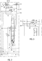
- Fig. 1
- ein Blockschaltbild einer Elektrohydrauliksteuerung einer ersten Ausführungsform, in drucklosem Zustand,
- Fig. 2
- ein Blockschaltbild einer weiteren Ausführungsform,
- Fig. 3
- einen Teil eines Blockschaltbildes einer Detailvariante,
- Fig. 4
- ein Blockschaltbild einer weiteren Ausführungsform,
- Fig. 5
- ein Blockschaltbild einer weiteren Ausführungsform, wobei zusätzliche Ausstattungsdetails gezeigt sind, die auch in den anderen Ausführungsformen implementiert sein können,
- Fig. 6
- ein Blockschaltbild einer weiteren Ausführungsform,
- Fig. 7
- ein Blockschaltbild einer weiteren Ausführungsform,
- Fig. 8
- ein Blockschaltbild einer noch weiteren Ausführungsform,
- Fig. 9
- ein Blockschaltbild einer weiteren Ausführungsform,
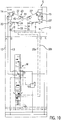
- Fig. 10
- ein Blockschaltbild einer weiteren Ausführungsform, und
- Fig. 11
- ein Blockschaltbild einer weiteren Ausführungsform.
- Die unterschiedlichen Ausführungsformen der Elektrohydrauliksteuerung S in den
Fig. 1 bis 11 können Teil einer nicht näher gezeigten elektronischen Hubwerksregelung EHR (Fig. 1 ) sein, wie sie in unterschiedlichen fahrbaren Arbeitsgeräten eingesetzt wird. Alternativ können solche Elektrohydrauliksteuerungen jedoch auch auf anderen Gebieten der mobilen oder stationären Hochdruckhydraulik Verwendung finden, zweckmäßig um kritische Lastbewegungen zumindest zu minimieren, ohne dass sich ein Bediener der Elektrohydrauliksteuerung notwendigerweise darum zu kümmern braucht. - Eine Elektrohydrauliksteuerung S gemäß
Fig. 1 , beispielsweise als Teil einer elektrohydraulischen Hubwerksregelung EHR, wird von einer Druckquelle in einer Druckleitung 1 versorgt und ist an eine Rücklaufleitung 2 angeschlossen. Eine nicht gezeigte Steuerdruckversorgung ist an eine Steuerdruckleitung 3 angeschlossen, während eine weitere Tankleitung 3' zu einem Tank beispielsweise der Steuerdruckversorgung führt. Eine weitere Steuerleitung 4 ist an einen Lastdrucksignalkreis LS angeschlossen. - Die Elektrohydrauliksteuerung S dient zum Betätigen eines doppelt wirkenden Hydroverbrauchers Z, beispielsweise eines doppelt wirkenden Hydrozylinders, mit dem eine Last L in unterschiedlichen Richtungen mit exakt einstellbaren Geschwindigkeiten bewegbar und jeweils in bestimmten Lagen haltbar ist, und zwar über einen Mehrwege-Mehrstellungs-Richtungsschieber W, der in der gezeigten Ausführungsform als 4/3-Wege-Proportional-Richtungsschieber mit einem symbolisch angedeuteten Schieberkolben 5 ausgebildet ist. An der Druckseite ist ein Zulaufregler 6 vorgesehen. Der Kolbenschieber 5 ist über Druckvorsteuerungen 7, 8, beispielsweise jeweils mit einem Druckminderventil (nicht gezeigt), und zwei Proportionalmagneten 9, 10 zwischen insgesamt drei Stellungen bewegbar, nämlich einer unteren Steuerstellung a, einer oberen Steuerstellung b und einer Nullstellung O, in der angeschlossene Arbeitsleitungen 12, 13 zum Rücklauf 2 entlastet sind. Eine Federanordnung 11 hilft beispielsweise mit. die mittlere Nullstellung einzustellen. Die Druckvorsteuerungen 7, 8 sind über eine Leitung 31 an die Steuerleitung 3 angeschlossen, und über eine Leitung 32 an die Tankleitung 3'.
- In jeder Arbeitsleitung 12, 13 ist ein Lasthalteventil 14 bzw. 15 angeordnet. In der in
Fig. 1 gezeigten Ausführungsform umfasst jedes Lasthalteventil 14, 15 ein durch eine Feder 17 in Sperrrichtung belastetes Ablassventil 16, das von einem Rückschlagventil 20 in einer Bypassschleife umgangen wird. Das Rückschlagventil 20 sperrt in Abströmrichtung aus dem Hydroverbraucher Z. Das Absperrventil 16 ist in Sperrrichtung zusätzlich von stromab des Rückschlagventils 20 aus der Arbeitsleitung 12 über eine Vorsteuerleitung 19 druckvorgesteuert, und an einer Aufsteuerseite 21 von stromab des Rückschlagventils 20 aus der Arbeitsleitung 12 druckvorgesteuert, sowie an einen Vorsteuerkreis K angeschlossen. - Jede Aufsteuerseite 21, 21' des Lasthalteventils 14, 15 ist an eine Steuerleitung 22, 22' angeschlossen, in der in der gezeigten Ausführungsform je eine Düse 23 bzw. 23' als Teil einer in den Vorsteuerkreis K integrierten Dämpfungsvorrichtung D vorgesehen ist. Die Düsen 23, 23' können gleich groß oder verschieden groß sein. Die Steuerleitungen 22, 22' führen überkreuz zu Wechselventilen 24, 24', die an einem Knoten 26 miteinander verbunden sind, und zu denen von den Arbeitsleitungen 12, 13 z.B. über Filter abzweigende Steuerleitungen 25, 25' führen, um die Lasthalteventile 14, 15 in den Steuerstellungen a, b jeweils überkreuz aufzusteuern. Wird beispielsweise die Arbeitsleitung 12 mit Druck beaufschlagt (Ausfahren des Hydroverbrauchers Z), dann passiert das Druckmittel über das Rückschlagventil 20 das geschlossene Absperrventil 16, während gleichzeitig der Druck aus der Arbeitsleitung 12 über die Steuerleitung 25, das Wechselventil 24 und die Steuerleitung 22' das Lasthalteventil 15 an seiner Aufsteuerseite 21' aufsteuert, so dass das Druckmittel aus dem Hydroverbraucher Z über die Arbeitsleitung 13 ausgeschoben werden kann. Ein weiterer Teil der in den Vorsteuerkreis K integrierten Dämpfungsvorrichtung D ist ein 3/2-Wege-Proportionaldruckregelventil 27, das durch einen Proportionalmagneten 28 gegen Federkraft aus der gezeigten Stellung verstellbar ist, in der eine Rücklaufleitung 29 mit dem Knoten 26 verbunden ist, während eine Steuerleitung 30, die einen Steuerdruck führt, abgesperrt ist. Die Steuerleitung 30 führt zu der Steuerleitung 3, welche an die Steuerdruckversorgung angeschlossen ist, um beispielsweise einen Steuerdruck von etwa 20 bis 30 bar im Wesentlichen konstant bereitstellt.
- Die Nullstellung O des 4/3-Wege-Proportional-Richtungsschiebers W wird sowohl zu einer hydraulischen Blockierung des Hydroverbrauchers Z in seiner jeweiligen Stellung (Halten der Last L) genutzt, als auch zum Einstellen einer Schwimmstellung, in der beide Arbeitsleitungen 12, 13 mit dem Rücklauf 2 verbunden sind. Nur zum Einstellen der Schwimmstellung werden bei in der Nullstellung O befindlichem Proportional-Richtungsschieber W die beiden Lasthalteventile 14, 15 über die Dämpfungsvorrichtung D aus der Steuerleitung 30 geregelt aufgesteuert, wofür der Proportionalmagnet 28 entsprechend bestromt wird. In Verbindung mit den Düsen 22, 23 und der Wahl der Beaufschlagungsstärke des Proportionalmagneten 28 werden die Lasthalteventile 14, 15 nur teilweise bzw. verzögert aufgesteuert, so dass eine Bewegung der Last L zeitlich verzögert abläuft. Je stärker der Proportionalmagnet 28 bestromt wird, desto mehr Druck wird aus der Steuerleitung 30 in die Rücklaufleitung 29 abgebaut, und umso weniger weit werden die Lasthalteventile 14, 15 aufgesteuert. Die Lasthalteventile fungieren dann als Bremsventile oder Drosseln, die die Lastbewegung nur verzögert ablaufen lassen, obwohl der 4/3-Wege-Proportionalrichtungsschieber W in seiner Nullstellung steht und beide Arbeitsleitungen 12, 13 mit dem Rücklauf 2 verbindet.
- Die Ausführungsform der
Fig. 2 unterscheidet sich von der derFig. 1 durch die Ausbildung der Lasthalteventile 14, 15. In diesem Fall sind in den Arbeitsleitungen 12, 13 2/2-Wege-Druckregelventile 16' enthalten, in die das Rückschlagventil 20' integriert ist, und die durch je eine Feder 17 in Richtung zur Absperrstellung beaufschlagt und an der Aufsteuerseite 21 bzw. 21' aus dem Vorsteuerkreis K druckvorgesteuert sind. Der weitere Aufbau und die Funktion entsprechen denen der Ausführungsform derFig. 1 . Die 2/2-Wege-Druckregelventile 16' werden der zusätzlichen Aufgabe der Drosselung gegebenenfalls besser gerecht als die Absperrventile 16 inFig. 1 . -
Fig. 3 deutet eine Detailvariante an, bei der im Vorsteuerkreis ein 3/2-Wege-Magnetschaltventil 27' zwischen dem Knoten 26 einerseits, und der Rücklaufleitung 29 und der Steuerleitung 30 andererseits angeordnet ist, das durch einen Schwarz/Weiß-Magneten 28' zwischen den beiden Stellungen umschaltbar ist. Hierbei können die Düsen 22, 23' der Dämpfungsvorrichtung D für eine fest eingestellte Dämpfung bei einer Lastbewegung zumindest in der Schwimmstellung oder beim Übergang in die oder aus der Schwimmstellung sorgen. - Bei den vorerwähnten Ausführungsformen wäre es möglich, nur ein Lasthalteventil 14 oder 15 über die Dämpfungsvorrichtung D gedämpft arbeiten zu lassen, und das andere Lasthalteventil voll aufzusteuern.
- In der Ausführungsform der Elektrohydrauliksteuerung S in
Fig. 4 wird bei der Aufsteuerung der beiden Lasthalteventile 14, 15 ein Ungleichgewicht erzeugt, wofür die Dämpfungsvorrichtung D im Vorsteuerkreis entsprechend ausgebildet und verschaltet ist. - Ferner unterscheidet sich die Bereitstellung des Steuerdrucks zum Aufsteuern der Lasthalteventile 14, 15 von der der
Fig. 1 bis 3 , in dem inFig. 4 in der Nullstellung O zum Einstellen der Schwimmstellung beide Proportionalmagneten 9, 10 gleich bestromt werden, so dass die Druckvorsteuerungen 7, 8 z.B. gleiche Drücke führen, die über die Steuerleitungen 30a und 30b gleichzeitig in den Vorsteuerkreis K eingespeist werden. Entscheidend ist, dass beide Proportionalmagneten 9, 10 gleichzeitig und gleich bestromt werden, so dass der Schieber 5 die Nullstellung hält. Die Steuerdrücke in den Steuerleitungen 30a, 30b können durch Auswahl der Bestromung der Proportional magneten 9, 10 zwar untereinander gleich, aber in unterschiedliche Höhen eingestellt werden. - Die Dämpfungsvorrichtung D in
Fig. 4 ist über die Wechselventile 24, 24' und die Steuerleitungen 25, 25' an die Arbeitsleitungen 12, 13 angeschlossen. In der Nullstellung und zum Einstellen der Schwimmstellung werden die Wechselventile 24, 24' in die gezeigten Positionen geschaltet, in der der Steuerdruck in den Leitungen 30a, 30b über die Steuerleitungen 22, 22', hier ohne Düsen an den Aufsteuerseiten 21, zum Aufsteuern der Lasthalteventile 14, 15 benutzt wird. Da jedoch in der Steuerleitung 30a eine Düse 33 angeordnet ist, und stromab der Düse 33 eine Leitung 34 über eine Düse 35 zur Rücklaufleitung 29 geführt ist, während die Steuerleitung 30b direkt zum Wechselventil 24' (ohne Düse) verläuft, wird das linke Lasthalteventil 14 weniger weit aufgesteuert, so dass es drosselt und die Abströmung vom Druckmittel in der Arbeitsleitung 12 dämpft. Von den Steuerleitungen 25, 25' zweigen Verbindungen zur Rücklaufleitung 29 ab, in denen ebenfalls Düsen 38 enthalten sind, wobei stromab jeweils eines Filters 36 eine weitere Düse 37 platziert ist. In den Steuerleitungen 22, 22' oder nur in einer dieser Steuerleitungen kann eine Düse bzw. können Düsen angeordnet sein, ähnlich wie in denFig. 1 bis 3 . -
Fig. 5 verdeutlicht eine weitere Ausführungsform einer Elektrohydrauliksteuerung S, wobei gegenüber den vorher gezeigten zusätzliche Sektionen 41 und 47 dargestellt sind. Die Sektion 41 enthält Schockventile 42, die die Arbeitsleitungen 12, 13 mit den Steuerleitungen 22, 22' verbinden und bei einer Schockkondition ansprechen können. Die Sektion 47 dient hingegen zu einer zusätzlichen Druckregelung, ähnlich einer Sekundärdruckbegrenzung, vorwiegend des Drucks in den Arbeitsleitungen 12, 13 in den Steuerstellungen des 4/3-Wege-Proportional-Richtungsschiebers W. Die Sektion 47 enthält ein 2/2-Drosselventil, das zwischen einer Absperrstellung und drosselnden Regelstellungen druck- und federabhängig verstellbar ist, sowie ein Wechselventil 49, das an den Lastdrucksignalkreis angeschlossen ist, und ein durch einen Proportionalmagneten gegen einstellbare Federkraft verstellbares Ablassventil 50 zum Rücklauf. - Die Dämpfungsvorrichtung D im Vorsteuerkreis der Lasthalteventile 14, 15 enthält in
Fig. 5 das anhand derFig. 1 und2 erläuterte 3/2-Wege-Proportionaldruckregelventil 27, das durch eine Feder 55 in einer ersten Schaltstellung gehalten wird, und bei Bestromen eines Proportionalmagneten 28 in regelnde Stellungen umstellbar ist. Die beiden Steuerleitungen 30a, 30b sind über Rückschlagventile 39 an einem Knoten 40 zusammengeführt und an einen Eingang des 3/2-Wege-Proportionaldruckregelventil 27 angeschlossen, dessen anderer Eingang mit der Rücklaufleitung 29 verbunden ist. Andererseits ist das 3/2-Wege-Proportionaldruckregelventil 27 mit dem Knoten 26 verbunden, der in einer die Steuerleitungen 25, 25' verbindenden Leitung 54 zwischen zwei Paaren gegensinniger Rückschlagventile 46, 46' liegt. Zwischen den beiden Rückschlagventilen jedes Rückschlagventilpaares 46, 46' sind die Steuerleitungen 22, 22' angeschlossen. Zusätzlich umfasst die Dämpfungsvorrichtung D inFig. 5 in den beiden Steuerleitungen 22, 22' angeordnete Rückström-Dämpfsysteme 43 (optional), jeweils bestehend aus einem in Rückstromrichtung sperrenden Rückschlagventil 44 und einer Düse 45 in einer Umgehungsschlaufe des Rückschlagventils 44. Mittels des 3/2-Wege-Proportionaldruckregelventils 27 lässt sich nach Maßgabe der Bestromung des Proportionalmagneten 28 die Dämpfung bei der Aufsteuerung der Lasthalteventile 14, 15 variabel modulieren oder regeln. Die Zusteuerbewegungen der Lasthalteventile 14, 15 können über die Abström-Dämpfsysteme 43 gleichartig oder verschieden gedämpft werden (je nach Düsenbestückung). Es könnte alternativ nur ein Abströmdämpfsystem 43 in einer Steuerleitung angeordnet sein. - Bei der Ausführungsform der Elektrohydrauliksteuerung S in
Fig. 6 wird die Aufsteuerung bzw. Zusteuerung der Lasthalteventile 14, 15 dadurch gedämpft, dass die Druckregelsektion 47 (sieheFig. 5 ) über jeweils ein Rückschlagventil jedes Rückschlagventilpaares 46, 46' und Verbindungsleitungen von den Steuerleitungen 22, 22' zum 2/2-Wege-Drosselventil 48 an den Vorsteuerkreis K angeschlossen ist, wobei die Steuerleitungen 22, 22' zwei weitere Wechselventile 51, 51' enthalten, von denen Leitungen 52, 52' zu den Steuerleitungen 25, 25' führen. Zwischen zumindest einem Wechselventil 51, 51' und der jeweiligen Aufsteuerseite eines Lasthalteventils 14, 15 kann gegebenenfalls ein Rückström-Dämpfsystem 43 (nicht gezeigt) wie inFig. 5 enthalten sein. Über den Proportionalmagneten des Ablassventils 50 lässt sich die Dämpfung zumindest beim Aufsteuern der Lasthalteventile 14, 15 variieren. Die Steuerleitungen 30a, 30b von den Druckvorsteuerungen des 4/3-Wege-Proportional-Richtungsschiebers W sind an die Wechselventile 24, 24' angeschlossen, um in der Nullstellung die Lasthalteventile 14, 15 gedämpft aufsteuern zu können. - Die in den Vorsteuerkreis K in
Fig. 7 integrierte Dämpfungsvorrichtung D zumindest zum Aufsteuern der Lasthalteventile 14, 15 unterscheidet sich von denen der vorhergehenden Ausführungsformen hauptsächlich dadurch, dass ein 2/2-Proportional-Drosselventil 27" (elektroproportionale Drossel) zwischen dem Knoten 26 in der Steuerleitung 54 und der Rücklaufleitung 29 vorgesehen ist. Der Knoten 26 liegt zwischen den Rückschlagventilen des gegensinnigen Rückschlagventilpaares 46, die in Strömungsrichtung zu den Wechselventilen 24, 24' sperren. Die Steuerleitungen 25, 25' zum Aufsteuern der Lasthalteventile 14, 15 überkreuz in den Steuerstellungen des 4/3-Wege-Proportional-Richtungsschiebers W sind ebenfalls an die Wechselventile 24, 24' angeschlossen und über die Düsen 37 und 38 mit der Rücklaufleitung 29 verbunden. - Die Ausführungsform der Elektrohydrauliksteuerung S in
Fig. 8 ist der vonFig. 5 ähnlich. Eine variable Dämpfung des Aufsteuerns der Lasthalteventile 14, 15 ist nicht nur am Übergang in die oder aus der und während der Schwimmstellung möglich, sondern auch in den Steuerstellungen des 4/3-Wege-Proportional-Richtungsschiebers W, aus dessen Druckvorsteuerungen 7, 8 die Steuerleitungen 30a, 30b gespeist werden, die über Rückschlagventile 39 zusammengeführt und an einen Anschluss des 3/2-Wege-Proportionaldruckregelventils 27 angeschlossen sind, dessen zweiter Anschluss mit der Rücklaufleitung 29 verbunden ist. Auf der anderen Seite ist das 3/2-Wege-Proportionaldruckregelventil 27 mit dem Knoten 26 in der Steuerleitung 54 verbunden, in der die beiden Rückschlagventilpaare 46, 46' angeordnet sind. Die Dämpfung lässt sich über den Proportionalmagneten 28 variieren. - Die Ausführungsform der Elektrohydrauliksteuerung S in
Fig. 9 ist der vonFig. 8 ähnlich. Jedoch wird nur das rechte Lasthalteventil 15 (z.B. benutzt zum Senken der Last L) gedämpft aufgesteuert oder zugesteuert, während das linke Lasthalteventil 14 aus der Steuerleitung 25' beaufschlagt werden kann, oder gar nicht. Die Düsenbestückung in der Dämpfungsvorrichtung D trägt ferner zu einer zusätzlichen oder grundsätzlichen Dämpfung bei. - Die Ausführungsform der Elektrohydrauliksteuerung S in
Fig. 10 ähnelt der derFig. 4 . Jedoch sind zusätzlich Abström-Dämpfsysteme 43 in den Steuerleitungen 22, 22' zu den Aufsteuerseiten der Lasthalteventile 14, 15 vorgesehen. Hiermit lässt sich auch die Zusteuerbewegung jedes Lasthalteventils 14, 15 gedämpft ausführen. Es könnte gegebenenfalls auch nur ein Abström-Dämpfsystem 43 in einer der beiden Steuerleitungen 22, 22' vorgesehen sein. - In der Ausführungsform der Elektrohydrauliksteuerung S in
Fig. 11 wird die Dämpfung zumindest bei der Aufsteuerung der Lasthalteventile 14, 15 über die proportional geregelten Drücke in den Steuerleitungen 30a, 30b von den Druckvorsteuerungen 7, 8 des 4/3-Wege-Proportional-Richtungsschiebers W variiert. Die Proportionalmagneten 9, 10 werden gleich, aber unterschiedlich bestromt, um das Aufsteuern zeitlich zu verzögern oder nur teilweise aufzusteuern und so zu dämpfen. Zusätzlich sind bei dieser Ausführungsform in den Arbeitsleitungen 12, 13 Rückström-Dämpfsysteme 43 enthalten, jeweils mit einem Rückschlagventil 44, das in Abströmrichtung sperrt, und einer Düse 45 in der das Rückschlagventil 44 umgehenden Leitungsschleife. - Obwohl in den Ausführungsformen der
Fig. 4 bis 11 die Steuerdrücke aus den Steuerleitungen 30a, 30b von den Druckvorsteuerungen des 4/3-Wege-Proportional-Richtungsschiebers W abgeleitet werden, könnte alternativ auch in den Ausführungsformen derFig. 4 bis 9 direkt der Steuerdruck von der Steuerdruckversorgung unter Umgehen der Druckvorsteuerungen abgegriffen werden. - Die Dämpfungsfunktion der Dämpfungsvorrichtung D könnte beispielsweise mittels eines Druckknopfes oder einer Programmroutine in einer elektronischen Steuerung der Elektrohydrauliksteuerung aktiviert werden oder sein, und dann automatisch ausgeführt werden, ohne dass sich ein Bediener darum zu kümmern braucht. Somit würde ein ausgehobenes Anbaugerät bei Einstellen der Schwimmstellung automatisch langsam bis in Bodenkontakt abgesenkt werden, auch nach einer Springbewegung bei Überfahren einer Erhebung, und könnte sogar in einer Steuerstellung beispielsweise mit eingestelltem Bodendruck eines Anbaugerätes dieses nach einer Springbewegung aufgrund einer Bodenerhebung wieder verlangsamt bis in Bodenkontakt und bis zum Aufbauen des eingestellten Bodendrucks abgesenkt werden. Bei einem Pistenpflegefahrzeug kann so ein deutlich verbessertes Arbeitsergebnis erzielt werden.
Claims (13)
- Elektrohydrauliksteuerung (S) wenigstens eines doppelt wirkenden Hydroverbrauchers (Z) zum Bewegen einer Last (L) über einen Druckvorsteuerungen (7, 8) aufweisenden Mehrwege-Mehrstellungs-Richtungsschieber (W), mit in Arbeitsleitungen (12, 13) des Hydroverbrauchers (Z) angeordneten, zumindest mit Steuerdruck aus einem an eine Steuerdruckversorgung (3) angeschlossenen Vorsteuerkreis (K) hydraulisch aufsteuerbaren Lasthalteventilen (14, 15), wobei der Mehrwege-Mehrstellungs-Schieber (W) eine Nullstellung aufweist, in der die Arbeitsleitungen (12, 13) von einer Druckquelle (1) isoliert und abgesperrt sind, und wobei eine Schwimmstellung einstellbar ist, in der die von der Druckquelle (1) isolierten Arbeitsleitungen (12, 13) mit einem Rücklauf (2) verbunden sind, dadurch gekennzeichnet, dass der Mehrwege-Mehrstellungs-Richtungsschieber (W) ein 4/3-Proportionalschieber ist und die Schwimmstellung in der Nullstellung (O) mit im 4/3-Proportionalschieber von der Druckquelle (1) isolierten, und zum Rücklauf (2) durchgängigen Arbeitsleitungen (12, 13) durch Aufsteuern der Lasthalteventile (14, 15) einstellbar ist, dass der Vorsteuerkreis (K) der Lasthalteventile (14, 15) eine Dämpfungsvorrichtung (D) aufweist, die zumindest beim Übergang in die oder aus der und/oder in der Schwimmstellung die Aufsteuerung zumindest eines der Lasthalteventile (14, 15) mit entweder fest eingestellter oder variabler Dämpfung dämpft, und dass die Schwimmstellung in der Nullstellung (O) durch Aufsteuern der Lasthalteventile (14, 15) über die Dämpfungsvorrichtung (D) entweder direkt aus den beiden gleichzeitig und gleichartig proportional gesteuerten, an die Steuerdruckversorgung (3) angeschlossenen Druckvorsteuerungen (7, 8), oder direkt mit Steuerdruck aus der Steuerdruckversorgung (3) einstellbar ist.
- Elektrohydrauliksteuerung nach Anspruch 1, dadurch gekennzeichnet, dass die Dämpfungsvorrichtung (D) im Vorsteuerkreis (K) für eine fest eingestellte Dämpfung wenigstens eine Düse (23, 23', 33, 35, 45) enthält.
- Elektrohydrauliksteuerung nach Anspruch 1, dadurch gekennzeichnet, dass die variable Dämpfung über die Dämpfungsvorrichtung (D) aus den Druckvorsteuerungen (7, 8) des 4/3-Proportionalschiebers mittels der Proportionalmagneten (9, 10) proportional ausführbar ist.
- Elektrohydrauliksteuerung nach Anspruch 1, dadurch gekennzeichnet, dass die Dämpfungsvorrichtung (D) zur variablen Dämpfung zwischen der Steuerdruckversorgung (3) bzw. den Druckvorsteuerungen (7, 8) und dem Rücklauf (2) und den Aufsteuerseiten (21, 21') der Lasthalteventile (14, 15) ein 3/2-Wege-Proportionaldruckregelventil (27) oder ein 3/2-Wege-Schwarz/Weiß-Schaltventil (27') enthält, vorzugsweise an der den Lasthalteventilen (14, 15) abgewandten Seite zweier Wechselventile (24, 24') und/oder wenigstens eines Rückschlagventil-Paares (46, 46') aus gegensinnig verschalteten Rückschlagventilen.
- Elektrohydrauliksteuerung nach Anspruch 1, dadurch gekennzeichnet, dass die Dämpfungsvorrichtung (D) zur variablen Dämpfung zwischen dem Rücklauf (2, 29) und den an die Steuerdruckversorgung (3) oder die Druckvorsteuerungen (7, 8) angeschlossenen Aufsteuerseiten (21, 21') der Lasthalteventile (14, 15) ein, vorzugsweise elektroproportionales, 2/2-Wege-Drosselventil aufweist, vorzugsweise an der den Lasthalteventilen (14, 15) abgewandten Seite zweier Wechselventile (24, 24') und/oder wenigstens eines Rückschlagventilpaares (46, 46').
- Elektrohydrauliksteuerung nach Anspruch 1, dadurch gekennzeichnet, dass eine an die Arbeitsleitungen (12, 13) angeschlossene Proportionaldruckregelsektion (47) für die Arbeitsdrücke in den Arbeitsleitungen (12, 13) in Steuerstellungen des 4/3-Proportionalschiebers vorgesehen ist, und dass der Vorsteuerkreis (K) zum Ausführen der variablen Dämpfung abströmseitig an die Proportionaldruckregelsektion (47) angeschlossen und über die Proportional-Druckregelsektion (47) zum Rücklauf (2) geregelt entlastbar ist.
- Elektrohydrauliksteuerung nach Anspruch 1, dadurch gekennzeichnet, dass die fest eingestellte oder die variable Dämpfung für beide Lasthalteventile (14, 15) gleich oder verschieden ist.
- Elektrohydrauliksteuerung nach Anspruch 1, dadurch gekennzeichnet, dass die fest eingestellte oder die variable Dämpfung über die Dämpfungsvorrichtung (D) auch in zumindest einer Steuerstellung (a, b) des 4/3-Proportionalschiebers außerhalb der Nullstellung einstellbar ist.
- Elektrohydrauliksteuerung nach Anspruch 2, dadurch gekennzeichnet, dass im Vorsteuerkreis (K) jeweils eine Düse (23, 23') an der Aufsteuerseite (21, 21') des Lasthalteventils (14, 15) angeordnet ist, wobei die Düsen gleich oder unterschiedlich bemessen sind.
- Elektrohydrauliksteuerung nach Anspruch 1, dadurch gekennzeichnet, dass von den Druckvorsteuerungen (7, 8) des 4/3-Proportionalschiebers getrennte Steuerleitungen (30a, 30b) zu je einem von zwei Wechselventilen (24, 24') im Vorsteuerkreis (K) führen, und dass in nur einer der Steuerleitungen (30a, 30b) eine Düse (33) angeordnet ist.
- Elektrohydrauliksteuerung nach wenigstens einem der vorhergehenden Ansprüche, dadurch gekennzeichnet, dass in den Arbeitsleitungen (12, 13) und/oder in Steuerleitungen (22, 22') zu den Aufsteuerseiten (21, 21') der Lasthalteventile (14, 15) Rückström-Dämpfsysteme (43) angeordnet sind, vorzugsweise bestehend jeweils aus einem in Abströmrichtung sperrenden Rückschlagventil (44) und einer das Rückschlagventil (44) umgehenden Düse (45).
- Elektrohydrauliksteuerung nach Anspruch 1, dadurch gekennzeichnet, dass jedes Lasthalteventil (14, 15) entweder ein von einem Rückschlagventil (20) in Zuströmrichtung umgehbares Ablassventil (16) aufweist, das an einer Zusteuerseite zuströmseitig aus der Arbeitsleitung (12, 13) druckvorgesteuert und federbelastet und an der Aufsteuerseite (21, 21') stromab des Rückschlagventils (20) aus der Arbeitsleitung (12, 13) und aus dem Vorsteuerkreis (K) druckvorgesteuert ist, oder ein 2/2-Wege-Druckregelventil (16') mit integriertem Rückschlagventil (20') aufweist, wobei das 2/2-Wege-Druckregelventil (16') durch Federkraft (17) zu einer Rückström-Sperrstellung beaufschlagt und zu variablen Durchgangsstellungen aus dem Vorsteuerkreis (K) druckvorgesteuert ist.
- Elektronische Hubwerksregelung (EHR) eines mobilen Arbeitsfahrzeuges mit wenigstens einem über den Hydroverbraucher (Z) betätigbaren Anbaugerät und mit einer Elektrohydrauliksteuerung (S) nach wenigstens einem der vorhergehenden Ansprüche.
Priority Applications (1)
| Application Number | Priority Date | Filing Date | Title |
|---|---|---|---|
| EP12179874.8A EP2696080B1 (de) | 2012-08-09 | 2012-08-09 | Elektrohydrauliksteuerung |
Applications Claiming Priority (1)
| Application Number | Priority Date | Filing Date | Title |
|---|---|---|---|
| EP12179874.8A EP2696080B1 (de) | 2012-08-09 | 2012-08-09 | Elektrohydrauliksteuerung |
Publications (2)
| Publication Number | Publication Date |
|---|---|
| EP2696080A1 EP2696080A1 (de) | 2014-02-12 |
| EP2696080B1 true EP2696080B1 (de) | 2016-12-14 |
Family
ID=46634064
Family Applications (1)
| Application Number | Title | Priority Date | Filing Date |
|---|---|---|---|
| EP12179874.8A Not-in-force EP2696080B1 (de) | 2012-08-09 | 2012-08-09 | Elektrohydrauliksteuerung |
Country Status (1)
| Country | Link |
|---|---|
| EP (1) | EP2696080B1 (de) |
Families Citing this family (2)
| Publication number | Priority date | Publication date | Assignee | Title |
|---|---|---|---|---|
| US10820470B2 (en) | 2018-08-24 | 2020-11-03 | Cnh Industrial America Llc | Hydraulic system for an agricultural implement incorporating implement-based hydraulic load sensing |
| US10820471B2 (en) | 2018-08-24 | 2020-11-03 | Cnh Industrial America Llc | Hydraulic system for an agricultural implement incorporating an implement-based override valve |
Family Cites Families (7)
| Publication number | Priority date | Publication date | Assignee | Title |
|---|---|---|---|---|
| DE4021347A1 (de) * | 1990-07-05 | 1992-01-16 | Heilmeier & Weinlein | Hydraulische steuervorrichtung |
| DE19919014C2 (de) | 1999-04-27 | 2001-03-01 | Danfoss Fluid Power As Nordbor | Hydraulikventil mit einer Verriegelungs- und einer Schwimmfunktion |
| DE19931142C2 (de) * | 1999-07-06 | 2002-07-18 | Sauer Danfoss Holding As Nordb | Hydraulische Ventilanordnung mit Verriegelungsfunktion |
| EP1528264A1 (de) * | 2003-10-30 | 2005-05-04 | OIL CONTROL S.p.A. | Ventil mit einem Druckspeicher zur Dämpfung der Steuerdruckschwingungen |
| DE102004033316A1 (de) | 2004-07-09 | 2006-02-09 | Bosch Rexroth Aktiengesellschaft | Verfahren zur Ansteuerung einer Hubwerksventilanordnung |
| KR100849500B1 (ko) * | 2006-11-29 | 2008-07-31 | 볼보 컨스트럭션 이키프먼트 홀딩 스웨덴 에이비 | 플로팅 기능이 구비된 더블 체크밸브 |
| EP2466153B1 (de) | 2010-12-17 | 2013-08-14 | HAWE Hydraulik SE | Elektrohydraulische Steuervorrichtung |
-
2012
- 2012-08-09 EP EP12179874.8A patent/EP2696080B1/de not_active Not-in-force
Non-Patent Citations (1)
| Title |
|---|
| None * |
Also Published As
| Publication number | Publication date |
|---|---|
| EP2696080A1 (de) | 2014-02-12 |
Similar Documents
| Publication | Publication Date | Title |
|---|---|---|
| EP2031256B1 (de) | Hubwerk und Verfahren zum Ansteuern eines Hubwerkes | |
| EP0499694B1 (de) | Hydraulische Steuervorrichtung | |
| EP1092095B2 (de) | Hydraulische schaltung | |
| DE69617634T2 (de) | Hydraulische steuervorrichtung | |
| DE10344480B3 (de) | Hydraulische Ventilanordnung | |
| EP1766146B1 (de) | Hubwerksventilanordnung | |
| EP1355065B1 (de) | Hydraulische Steuerung | |
| EP0760908B1 (de) | Steueranordnung für wenigstens zwei hydraulische verbraucher | |
| DE102004050294B3 (de) | Hydraulische Ventilanordnung | |
| DE19754828C2 (de) | Hydraulische Steueranordnung für eine mobile Arbeitsmaschine, insbesondere für einen Radlader, zur Dämpfung von Nickschwingungen | |
| EP1450048A1 (de) | Ventilanordnung | |
| DE102007029355A1 (de) | Hydraulische Steueranordnung | |
| EP1281872A1 (de) | Elektrohydraulische Einrichtung zur Steuerung eines doppelt wirkenden Motors | |
| EP2142808B1 (de) | Hydraulische steueranordnung | |
| DE19831595A1 (de) | Hydraulische Schaltung | |
| EP2171289A1 (de) | Steuervorrichtung für mindestens zwei hydraulische antriebe | |
| DE102008064064A1 (de) | Hydraulische Steueranordnung | |
| DE4231399A1 (de) | Hydraulische Steuereinrichtung | |
| DE19735482B4 (de) | Hydraulisches System mit einem Differentialzylinder und einem Eilgangventil | |
| EP2016818B1 (de) | Hubwerk und Verfahren zum Ansteuern eines derartigen Hubwerks | |
| EP2696080A1 (de) | Elektrohydrauliksteuerung | |
| DE19548943B4 (de) | Ventilanordnung | |
| EP2799722A1 (de) | Hydrauliksteuerung und Logikelement | |
| EP2157319B1 (de) | Hydrauliksteuerung für einen Hydromotor | |
| AT396618B (de) | Hydraulisches dreiwege-stetigventil für blockeinbau |
Legal Events
| Date | Code | Title | Description |
|---|---|---|---|
| 17P | Request for examination filed |
Effective date: 20130319 |
|
| AK | Designated contracting states |
Kind code of ref document: A1 Designated state(s): AL AT BE BG CH CY CZ DE DK EE ES FI FR GB GR HR HU IE IS IT LI LT LU LV MC MK MT NL NO PL PT RO RS SE SI SK SM TR |
|
| AX | Request for extension of the european patent |
Extension state: BA ME |
|
| PUAI | Public reference made under article 153(3) epc to a published international application that has entered the european phase |
Free format text: ORIGINAL CODE: 0009012 |
|
| GRAP | Despatch of communication of intention to grant a patent |
Free format text: ORIGINAL CODE: EPIDOSNIGR1 |
|
| INTG | Intention to grant announced |
Effective date: 20160706 |
|
| GRAS | Grant fee paid |
Free format text: ORIGINAL CODE: EPIDOSNIGR3 |
|
| GRAA | (expected) grant |
Free format text: ORIGINAL CODE: 0009210 |
|
| AK | Designated contracting states |
Kind code of ref document: B1 Designated state(s): AL AT BE BG CH CY CZ DE DK EE ES FI FR GB GR HR HU IE IS IT LI LT LU LV MC MK MT NL NO PL PT RO RS SE SI SK SM TR |
|
| REG | Reference to a national code |
Ref country code: GB Ref legal event code: FG4D Free format text: NOT ENGLISH |
|
| REG | Reference to a national code |
Ref country code: CH Ref legal event code: EP |
|
| REG | Reference to a national code |
Ref country code: IE Ref legal event code: FG4D Free format text: LANGUAGE OF EP DOCUMENT: GERMAN |
|
| REG | Reference to a national code |
Ref country code: AT Ref legal event code: REF Ref document number: 853863 Country of ref document: AT Kind code of ref document: T Effective date: 20170115 |
|
| REG | Reference to a national code |
Ref country code: DE Ref legal event code: R096 Ref document number: 502012009010 Country of ref document: DE |
|
| PG25 | Lapsed in a contracting state [announced via postgrant information from national office to epo] |
Ref country code: LV Free format text: LAPSE BECAUSE OF FAILURE TO SUBMIT A TRANSLATION OF THE DESCRIPTION OR TO PAY THE FEE WITHIN THE PRESCRIBED TIME-LIMIT Effective date: 20161214 |
|
| REG | Reference to a national code |
Ref country code: LT Ref legal event code: MG4D |
|
| REG | Reference to a national code |
Ref country code: NL Ref legal event code: MP Effective date: 20161214 |
|
| PG25 | Lapsed in a contracting state [announced via postgrant information from national office to epo] |
Ref country code: LT Free format text: LAPSE BECAUSE OF FAILURE TO SUBMIT A TRANSLATION OF THE DESCRIPTION OR TO PAY THE FEE WITHIN THE PRESCRIBED TIME-LIMIT Effective date: 20161214 Ref country code: GR Free format text: LAPSE BECAUSE OF FAILURE TO SUBMIT A TRANSLATION OF THE DESCRIPTION OR TO PAY THE FEE WITHIN THE PRESCRIBED TIME-LIMIT Effective date: 20170315 Ref country code: SE Free format text: LAPSE BECAUSE OF FAILURE TO SUBMIT A TRANSLATION OF THE DESCRIPTION OR TO PAY THE FEE WITHIN THE PRESCRIBED TIME-LIMIT Effective date: 20161214 Ref country code: NO Free format text: LAPSE BECAUSE OF FAILURE TO SUBMIT A TRANSLATION OF THE DESCRIPTION OR TO PAY THE FEE WITHIN THE PRESCRIBED TIME-LIMIT Effective date: 20170314 |
|
| PG25 | Lapsed in a contracting state [announced via postgrant information from national office to epo] |
Ref country code: FI Free format text: LAPSE BECAUSE OF FAILURE TO SUBMIT A TRANSLATION OF THE DESCRIPTION OR TO PAY THE FEE WITHIN THE PRESCRIBED TIME-LIMIT Effective date: 20161214 Ref country code: HR Free format text: LAPSE BECAUSE OF FAILURE TO SUBMIT A TRANSLATION OF THE DESCRIPTION OR TO PAY THE FEE WITHIN THE PRESCRIBED TIME-LIMIT Effective date: 20161214 Ref country code: RS Free format text: LAPSE BECAUSE OF FAILURE TO SUBMIT A TRANSLATION OF THE DESCRIPTION OR TO PAY THE FEE WITHIN THE PRESCRIBED TIME-LIMIT Effective date: 20161214 |
|
| PG25 | Lapsed in a contracting state [announced via postgrant information from national office to epo] |
Ref country code: NL Free format text: LAPSE BECAUSE OF FAILURE TO SUBMIT A TRANSLATION OF THE DESCRIPTION OR TO PAY THE FEE WITHIN THE PRESCRIBED TIME-LIMIT Effective date: 20161214 |
|
| PG25 | Lapsed in a contracting state [announced via postgrant information from national office to epo] |
Ref country code: IS Free format text: LAPSE BECAUSE OF FAILURE TO SUBMIT A TRANSLATION OF THE DESCRIPTION OR TO PAY THE FEE WITHIN THE PRESCRIBED TIME-LIMIT Effective date: 20170414 Ref country code: SK Free format text: LAPSE BECAUSE OF FAILURE TO SUBMIT A TRANSLATION OF THE DESCRIPTION OR TO PAY THE FEE WITHIN THE PRESCRIBED TIME-LIMIT Effective date: 20161214 Ref country code: RO Free format text: LAPSE BECAUSE OF FAILURE TO SUBMIT A TRANSLATION OF THE DESCRIPTION OR TO PAY THE FEE WITHIN THE PRESCRIBED TIME-LIMIT Effective date: 20161214 Ref country code: CZ Free format text: LAPSE BECAUSE OF FAILURE TO SUBMIT A TRANSLATION OF THE DESCRIPTION OR TO PAY THE FEE WITHIN THE PRESCRIBED TIME-LIMIT Effective date: 20161214 Ref country code: EE Free format text: LAPSE BECAUSE OF FAILURE TO SUBMIT A TRANSLATION OF THE DESCRIPTION OR TO PAY THE FEE WITHIN THE PRESCRIBED TIME-LIMIT Effective date: 20161214 |
|
| PG25 | Lapsed in a contracting state [announced via postgrant information from national office to epo] |
Ref country code: SM Free format text: LAPSE BECAUSE OF FAILURE TO SUBMIT A TRANSLATION OF THE DESCRIPTION OR TO PAY THE FEE WITHIN THE PRESCRIBED TIME-LIMIT Effective date: 20161214 Ref country code: ES Free format text: LAPSE BECAUSE OF FAILURE TO SUBMIT A TRANSLATION OF THE DESCRIPTION OR TO PAY THE FEE WITHIN THE PRESCRIBED TIME-LIMIT Effective date: 20161214 Ref country code: PL Free format text: LAPSE BECAUSE OF FAILURE TO SUBMIT A TRANSLATION OF THE DESCRIPTION OR TO PAY THE FEE WITHIN THE PRESCRIBED TIME-LIMIT Effective date: 20161214 Ref country code: PT Free format text: LAPSE BECAUSE OF FAILURE TO SUBMIT A TRANSLATION OF THE DESCRIPTION OR TO PAY THE FEE WITHIN THE PRESCRIBED TIME-LIMIT Effective date: 20170414 Ref country code: IT Free format text: LAPSE BECAUSE OF FAILURE TO SUBMIT A TRANSLATION OF THE DESCRIPTION OR TO PAY THE FEE WITHIN THE PRESCRIBED TIME-LIMIT Effective date: 20161214 Ref country code: BG Free format text: LAPSE BECAUSE OF FAILURE TO SUBMIT A TRANSLATION OF THE DESCRIPTION OR TO PAY THE FEE WITHIN THE PRESCRIBED TIME-LIMIT Effective date: 20170314 |
|
| REG | Reference to a national code |
Ref country code: DE Ref legal event code: R097 Ref document number: 502012009010 Country of ref document: DE |
|
| PLBE | No opposition filed within time limit |
Free format text: ORIGINAL CODE: 0009261 |
|
| STAA | Information on the status of an ep patent application or granted ep patent |
Free format text: STATUS: NO OPPOSITION FILED WITHIN TIME LIMIT |
|
| 26N | No opposition filed |
Effective date: 20170915 |
|
| PG25 | Lapsed in a contracting state [announced via postgrant information from national office to epo] |
Ref country code: DK Free format text: LAPSE BECAUSE OF FAILURE TO SUBMIT A TRANSLATION OF THE DESCRIPTION OR TO PAY THE FEE WITHIN THE PRESCRIBED TIME-LIMIT Effective date: 20161214 |
|
| PG25 | Lapsed in a contracting state [announced via postgrant information from national office to epo] |
Ref country code: SI Free format text: LAPSE BECAUSE OF FAILURE TO SUBMIT A TRANSLATION OF THE DESCRIPTION OR TO PAY THE FEE WITHIN THE PRESCRIBED TIME-LIMIT Effective date: 20161214 |
|
| REG | Reference to a national code |
Ref country code: CH Ref legal event code: PL |
|
| PG25 | Lapsed in a contracting state [announced via postgrant information from national office to epo] |
Ref country code: MC Free format text: LAPSE BECAUSE OF FAILURE TO SUBMIT A TRANSLATION OF THE DESCRIPTION OR TO PAY THE FEE WITHIN THE PRESCRIBED TIME-LIMIT Effective date: 20161214 |
|
| GBPC | Gb: european patent ceased through non-payment of renewal fee |
Effective date: 20170809 |
|
| PG25 | Lapsed in a contracting state [announced via postgrant information from national office to epo] |
Ref country code: LI Free format text: LAPSE BECAUSE OF NON-PAYMENT OF DUE FEES Effective date: 20170831 Ref country code: CH Free format text: LAPSE BECAUSE OF NON-PAYMENT OF DUE FEES Effective date: 20170831 |
|
| REG | Reference to a national code |
Ref country code: DE Ref legal event code: R082 Ref document number: 502012009010 Country of ref document: DE Representative=s name: GROSSE, SCHUMACHER, KNAUER, VON HIRSCHHAUSEN, DE Ref country code: DE Ref legal event code: R081 Ref document number: 502012009010 Country of ref document: DE Owner name: HAWE HYDRAULIK SE, DE Free format text: FORMER OWNER: HAWE HYDRAULIK SE, 81673 MUENCHEN, DE |
|
| REG | Reference to a national code |
Ref country code: FR Ref legal event code: ST Effective date: 20180430 |
|
| REG | Reference to a national code |
Ref country code: IE Ref legal event code: MM4A |
|
| REG | Reference to a national code |
Ref country code: BE Ref legal event code: MM Effective date: 20170831 |
|
| PG25 | Lapsed in a contracting state [announced via postgrant information from national office to epo] |
Ref country code: LU Free format text: LAPSE BECAUSE OF NON-PAYMENT OF DUE FEES Effective date: 20170809 |
|
| PG25 | Lapsed in a contracting state [announced via postgrant information from national office to epo] |
Ref country code: GB Free format text: LAPSE BECAUSE OF NON-PAYMENT OF DUE FEES Effective date: 20170809 Ref country code: IE Free format text: LAPSE BECAUSE OF NON-PAYMENT OF DUE FEES Effective date: 20170809 |
|
| PG25 | Lapsed in a contracting state [announced via postgrant information from national office to epo] |
Ref country code: BE Free format text: LAPSE BECAUSE OF NON-PAYMENT OF DUE FEES Effective date: 20170831 Ref country code: FR Free format text: LAPSE BECAUSE OF NON-PAYMENT OF DUE FEES Effective date: 20170831 |
|
| PG25 | Lapsed in a contracting state [announced via postgrant information from national office to epo] |
Ref country code: MT Free format text: LAPSE BECAUSE OF FAILURE TO SUBMIT A TRANSLATION OF THE DESCRIPTION OR TO PAY THE FEE WITHIN THE PRESCRIBED TIME-LIMIT Effective date: 20161214 |
|
| REG | Reference to a national code |
Ref country code: AT Ref legal event code: MM01 Ref document number: 853863 Country of ref document: AT Kind code of ref document: T Effective date: 20170809 |
|
| PG25 | Lapsed in a contracting state [announced via postgrant information from national office to epo] |
Ref country code: AT Free format text: LAPSE BECAUSE OF NON-PAYMENT OF DUE FEES Effective date: 20170809 |
|
| PG25 | Lapsed in a contracting state [announced via postgrant information from national office to epo] |
Ref country code: HU Free format text: LAPSE BECAUSE OF FAILURE TO SUBMIT A TRANSLATION OF THE DESCRIPTION OR TO PAY THE FEE WITHIN THE PRESCRIBED TIME-LIMIT; INVALID AB INITIO Effective date: 20120809 |
|
| PG25 | Lapsed in a contracting state [announced via postgrant information from national office to epo] |
Ref country code: CY Free format text: LAPSE BECAUSE OF NON-PAYMENT OF DUE FEES Effective date: 20161214 |
|
| PGFP | Annual fee paid to national office [announced via postgrant information from national office to epo] |
Ref country code: DE Payment date: 20190828 Year of fee payment: 8 |
|
| PG25 | Lapsed in a contracting state [announced via postgrant information from national office to epo] |
Ref country code: MK Free format text: LAPSE BECAUSE OF FAILURE TO SUBMIT A TRANSLATION OF THE DESCRIPTION OR TO PAY THE FEE WITHIN THE PRESCRIBED TIME-LIMIT Effective date: 20161214 |
|
| PG25 | Lapsed in a contracting state [announced via postgrant information from national office to epo] |
Ref country code: TR Free format text: LAPSE BECAUSE OF FAILURE TO SUBMIT A TRANSLATION OF THE DESCRIPTION OR TO PAY THE FEE WITHIN THE PRESCRIBED TIME-LIMIT Effective date: 20161214 |
|
| PG25 | Lapsed in a contracting state [announced via postgrant information from national office to epo] |
Ref country code: AL Free format text: LAPSE BECAUSE OF FAILURE TO SUBMIT A TRANSLATION OF THE DESCRIPTION OR TO PAY THE FEE WITHIN THE PRESCRIBED TIME-LIMIT Effective date: 20161214 |
|
| REG | Reference to a national code |
Ref country code: DE Ref legal event code: R119 Ref document number: 502012009010 Country of ref document: DE |
|
| PG25 | Lapsed in a contracting state [announced via postgrant information from national office to epo] |
Ref country code: DE Free format text: LAPSE BECAUSE OF NON-PAYMENT OF DUE FEES Effective date: 20210302 |