EP2696151A2 - Structure de support modulaire pour un système d'énergie solaire - Google Patents
Structure de support modulaire pour un système d'énergie solaire Download PDFInfo
- Publication number
- EP2696151A2 EP2696151A2 EP13003590.0A EP13003590A EP2696151A2 EP 2696151 A2 EP2696151 A2 EP 2696151A2 EP 13003590 A EP13003590 A EP 13003590A EP 2696151 A2 EP2696151 A2 EP 2696151A2
- Authority
- EP
- European Patent Office
- Prior art keywords
- suited
- supporting
- modular
- supporting structure
- panel
- Prior art date
- Legal status (The legal status is an assumption and is not a legal conclusion. Google has not performed a legal analysis and makes no representation as to the accuracy of the status listed.)
- Withdrawn
Links
- 230000002093 peripheral effect Effects 0.000 claims description 8
- 238000000034 method Methods 0.000 description 16
- 238000009434 installation Methods 0.000 description 12
- 238000007789 sealing Methods 0.000 description 10
- 230000008878 coupling Effects 0.000 description 8
- 238000010168 coupling process Methods 0.000 description 8
- 238000005859 coupling reaction Methods 0.000 description 8
- 238000010276 construction Methods 0.000 description 6
- 238000001125 extrusion Methods 0.000 description 5
- 239000003566 sealing material Substances 0.000 description 5
- 230000008569 process Effects 0.000 description 4
- 230000009471 action Effects 0.000 description 3
- 238000004519 manufacturing process Methods 0.000 description 3
- 230000008439 repair process Effects 0.000 description 3
- 238000004078 waterproofing Methods 0.000 description 3
- 238000009825 accumulation Methods 0.000 description 2
- 230000005540 biological transmission Effects 0.000 description 2
- 230000000694 effects Effects 0.000 description 2
- 238000009413 insulation Methods 0.000 description 2
- 238000012423 maintenance Methods 0.000 description 2
- 239000011159 matrix material Substances 0.000 description 2
- XLYOFNOQVPJJNP-UHFFFAOYSA-N water Substances O XLYOFNOQVPJJNP-UHFFFAOYSA-N 0.000 description 2
- 241001465754 Metazoa Species 0.000 description 1
- XAGFODPZIPBFFR-UHFFFAOYSA-N aluminium Chemical compound [Al] XAGFODPZIPBFFR-UHFFFAOYSA-N 0.000 description 1
- 229910052782 aluminium Inorganic materials 0.000 description 1
- 239000004411 aluminium Substances 0.000 description 1
- 230000015572 biosynthetic process Effects 0.000 description 1
- 239000006185 dispersion Substances 0.000 description 1
- 238000010438 heat treatment Methods 0.000 description 1
- 230000008595 infiltration Effects 0.000 description 1
- 238000001764 infiltration Methods 0.000 description 1
- 239000007769 metal material Substances 0.000 description 1
- 229920001296 polysiloxane Polymers 0.000 description 1
- 230000005855 radiation Effects 0.000 description 1
- 239000007787 solid Substances 0.000 description 1
- 238000009423 ventilation Methods 0.000 description 1
Images


Classifications
-
- H—ELECTRICITY
- H02—GENERATION; CONVERSION OR DISTRIBUTION OF ELECTRIC POWER
- H02S—GENERATION OF ELECTRIC POWER BY CONVERSION OF INFRARED RADIATION, VISIBLE LIGHT OR ULTRAVIOLET LIGHT, e.g. USING PHOTOVOLTAIC [PV] MODULES
- H02S20/00—Supporting structures for PV modules
- H02S20/20—Supporting structures directly fixed to an immovable object
- H02S20/22—Supporting structures directly fixed to an immovable object specially adapted for buildings
- H02S20/23—Supporting structures directly fixed to an immovable object specially adapted for buildings specially adapted for roof structures
-
- F—MECHANICAL ENGINEERING; LIGHTING; HEATING; WEAPONS; BLASTING
- F24—HEATING; RANGES; VENTILATING
- F24S—SOLAR HEAT COLLECTORS; SOLAR HEAT SYSTEMS
- F24S25/00—Arrangement of stationary mountings or supports for solar heat collector modules
- F24S25/30—Arrangement of stationary mountings or supports for solar heat collector modules using elongate rigid mounting elements extending substantially along the supporting surface, e.g. for covering buildings with solar heat collectors
- F24S25/33—Arrangement of stationary mountings or supports for solar heat collector modules using elongate rigid mounting elements extending substantially along the supporting surface, e.g. for covering buildings with solar heat collectors forming substantially planar assemblies, e.g. of coplanar or stacked profiles
- F24S25/35—Arrangement of stationary mountings or supports for solar heat collector modules using elongate rigid mounting elements extending substantially along the supporting surface, e.g. for covering buildings with solar heat collectors forming substantially planar assemblies, e.g. of coplanar or stacked profiles by means of profiles with a cross-section defining separate supporting portions for adjacent modules
-
- F—MECHANICAL ENGINEERING; LIGHTING; HEATING; WEAPONS; BLASTING
- F24—HEATING; RANGES; VENTILATING
- F24S—SOLAR HEAT COLLECTORS; SOLAR HEAT SYSTEMS
- F24S25/00—Arrangement of stationary mountings or supports for solar heat collector modules
- F24S25/30—Arrangement of stationary mountings or supports for solar heat collector modules using elongate rigid mounting elements extending substantially along the supporting surface, e.g. for covering buildings with solar heat collectors
- F24S25/33—Arrangement of stationary mountings or supports for solar heat collector modules using elongate rigid mounting elements extending substantially along the supporting surface, e.g. for covering buildings with solar heat collectors forming substantially planar assemblies, e.g. of coplanar or stacked profiles
- F24S25/37—Arrangement of stationary mountings or supports for solar heat collector modules using elongate rigid mounting elements extending substantially along the supporting surface, e.g. for covering buildings with solar heat collectors forming substantially planar assemblies, e.g. of coplanar or stacked profiles forming coplanar grids comprising longitudinal and transversal profiles
-
- F—MECHANICAL ENGINEERING; LIGHTING; HEATING; WEAPONS; BLASTING
- F24—HEATING; RANGES; VENTILATING
- F24S—SOLAR HEAT COLLECTORS; SOLAR HEAT SYSTEMS
- F24S25/00—Arrangement of stationary mountings or supports for solar heat collector modules
- F24S25/60—Fixation means, e.g. fasteners, specially adapted for supporting solar heat collector modules
- F24S25/63—Fixation means, e.g. fasteners, specially adapted for supporting solar heat collector modules for fixing modules or their peripheral frames to supporting elements
- F24S25/634—Clamps; Clips
-
- F—MECHANICAL ENGINEERING; LIGHTING; HEATING; WEAPONS; BLASTING
- F24—HEATING; RANGES; VENTILATING
- F24S—SOLAR HEAT COLLECTORS; SOLAR HEAT SYSTEMS
- F24S40/00—Safety or protection arrangements of solar heat collectors; Preventing malfunction of solar heat collectors
- F24S40/40—Preventing corrosion; Protecting against dirt or contamination
- F24S40/44—Draining rainwater or condensation
-
- Y—GENERAL TAGGING OF NEW TECHNOLOGICAL DEVELOPMENTS; GENERAL TAGGING OF CROSS-SECTIONAL TECHNOLOGIES SPANNING OVER SEVERAL SECTIONS OF THE IPC; TECHNICAL SUBJECTS COVERED BY FORMER USPC CROSS-REFERENCE ART COLLECTIONS [XRACs] AND DIGESTS
- Y02—TECHNOLOGIES OR APPLICATIONS FOR MITIGATION OR ADAPTATION AGAINST CLIMATE CHANGE
- Y02B—CLIMATE CHANGE MITIGATION TECHNOLOGIES RELATED TO BUILDINGS, e.g. HOUSING, HOUSE APPLIANCES OR RELATED END-USER APPLICATIONS
- Y02B10/00—Integration of renewable energy sources in buildings
- Y02B10/10—Photovoltaic [PV]
-
- Y—GENERAL TAGGING OF NEW TECHNOLOGICAL DEVELOPMENTS; GENERAL TAGGING OF CROSS-SECTIONAL TECHNOLOGIES SPANNING OVER SEVERAL SECTIONS OF THE IPC; TECHNICAL SUBJECTS COVERED BY FORMER USPC CROSS-REFERENCE ART COLLECTIONS [XRACs] AND DIGESTS
- Y02—TECHNOLOGIES OR APPLICATIONS FOR MITIGATION OR ADAPTATION AGAINST CLIMATE CHANGE
- Y02B—CLIMATE CHANGE MITIGATION TECHNOLOGIES RELATED TO BUILDINGS, e.g. HOUSING, HOUSE APPLIANCES OR RELATED END-USER APPLICATIONS
- Y02B10/00—Integration of renewable energy sources in buildings
- Y02B10/20—Solar thermal
-
- Y—GENERAL TAGGING OF NEW TECHNOLOGICAL DEVELOPMENTS; GENERAL TAGGING OF CROSS-SECTIONAL TECHNOLOGIES SPANNING OVER SEVERAL SECTIONS OF THE IPC; TECHNICAL SUBJECTS COVERED BY FORMER USPC CROSS-REFERENCE ART COLLECTIONS [XRACs] AND DIGESTS
- Y02—TECHNOLOGIES OR APPLICATIONS FOR MITIGATION OR ADAPTATION AGAINST CLIMATE CHANGE
- Y02E—REDUCTION OF GREENHOUSE GAS [GHG] EMISSIONS, RELATED TO ENERGY GENERATION, TRANSMISSION OR DISTRIBUTION
- Y02E10/00—Energy generation through renewable energy sources
- Y02E10/40—Solar thermal energy, e.g. solar towers
- Y02E10/47—Mountings or tracking
-
- Y—GENERAL TAGGING OF NEW TECHNOLOGICAL DEVELOPMENTS; GENERAL TAGGING OF CROSS-SECTIONAL TECHNOLOGIES SPANNING OVER SEVERAL SECTIONS OF THE IPC; TECHNICAL SUBJECTS COVERED BY FORMER USPC CROSS-REFERENCE ART COLLECTIONS [XRACs] AND DIGESTS
- Y02—TECHNOLOGIES OR APPLICATIONS FOR MITIGATION OR ADAPTATION AGAINST CLIMATE CHANGE
- Y02E—REDUCTION OF GREENHOUSE GAS [GHG] EMISSIONS, RELATED TO ENERGY GENERATION, TRANSMISSION OR DISTRIBUTION
- Y02E10/00—Energy generation through renewable energy sources
- Y02E10/50—Photovoltaic [PV] energy
Definitions
- the present invention concerns the technical field of the construction of systems that exploit solar energy to produce electrical energy and/or thermal energy, that is, photovoltaic systems or solar thermal systems.
- the present invention concerns the construction of photovoltaic systems or solar thermal systems suited to be installed on roofs.
- the present invention refers to the method of installation of said systems.
- a photovoltaic system or photovoltaic plant, is a system that is substantially constituted by the assembly of several photovoltaic modules, also called photovoltaic generators or solar photovoltaic panels, which exploit the incident solar energy to produce electrical energy through a photovoltaic effect.
- Solar photovoltaic panels are associated with further devices suited to manage and properly treat the energy generated by the same photovoltaic panels before it is directly used on site or in order to introduce it in the mains.
- a solar thermal system usually consists of a thermal solar panel, also called solar collector, which constitutes a device suited to convert sun radiation into thermal energy and to transfer it, for example, towards a heat accumulator for a successive use, typically in the form of hot water for heating and in some cases for the production of electrical energy.
- solar panels are assembled on a surface, preferably plane or even more preferably inclined, in order to exploit solar energy as much as possible and with the best possible angle of incidence. These solar panels are typically installed on the roof of civil or industrial buildings.
- the object is to integrate the solar panels as much as possible, in order to obtain continuity with roof tiles, gutters or other elements that make up the roof.
- solar panels are assembled side by side and then fixed firmly to the underlying surface of the roof.
- connection elements like screws, Fisher ® anchors, rivets or similar elements are used, which permanently secure suitable shaped portions of the solar panel in the points where holes for the passage of said connection elements are provided.
- a first drawback posed by these techniques lies in the complexity of the operations required to lay the panels on the underlying supporting surface.
- a further drawback posed by said installation techniques is represented by the difficulties that arise in case of maintenance and/or repair operations requiring the removal of one or more of said solar panels and their successive repositioning.
- a further drawback posed by the systems of the known art lies in the need to resort to finishing operations in order to make the surface made up by the solar panels as waterproof as possible and thus avoid water infiltrations in the underlying surface, in particular when said surface is constituted by the roof of a building.
- finishing operations typically comprise the application of sealing materials, usually silicone, in the fissures present between adjacent panels.
- shims are generally used to compensate for such differences and are interposed between the solar panel and the underlying surface.
- the main object of the present invention is thus to at least partially overcome said drawbacks.
- It is a further object of the present invention to provide a complete solar energy system comprising a system for fixing to the roof, a waterproofing system and a system for conveying rainwater.
- the present invention is based on the general consideration that it is desirable to be able to simplify the operations required for the installation of a solar energy system having one or more solar panels, by using a modular supporting structure comprising two elements suited to secure said solar panels to each other.
- the subject of the present invention therefore, is a modular supporting structure for a solar energy system of the type comprising at least one solar panel, said modular supporting structure being suited to be fixed to a supporting base and comprising:
- the first closing element and the first supporting element are suited to fix the solar panel when the first closing element is associated with the first supporting element.
- the first closing element and the first supporting element are suited to be arranged in contact with the first surface and the second surface of the panel at the level of a first peripheral edge of the panel itself.
- the modular structure also comprises:
- the second closing element and the second supporting element are suited to secure the solar panel when the second closing element is associated with the second supporting element.
- the second closing element and the second supporting element are suited to be arranged in contact with the first surface and the second surface of the panel at the level of a second peripheral edge of the panel itself.
- the modular structure comprises:
- the panel has preferably the shape of a parallelogram.
- the first supporting elements and the second supporting elements are properly suited to be arranged under a plurality of solar panels in such a way as to define a matrix structure.
- the second supporting elements comprise end portions suited to be connected to the first supporting elements.
- the first supporting elements, the first closing elements, the second supporting elements and the second closing elements develop longitudinally.
- said elements are of the section type, more preferably obtained through an extrusion process.
- the first supporting element comprises a seat suited to accommodate a gasket element.
- the gasket element is suited to be interposed between the first supporting element and the first surface of the panel.
- the first closing element comprises a seat suited to accommodate a gasket element.
- the gasket element is suited to be interposed between the first closing element and the second surface of the panel.
- the modular supporting structure properly comprises means suited to secure the first closing element to the first supporting element.
- said securing means comprise fixing screws.
- the modular supporting structure comprises at least one drainage element suited to be positioned at the periphery of the modular supporting structure, the drainage element being locked between the first closing element and the first supporting element when the first closing element is associated with the first supporting element.
- the drainage element comprises a fixing portion suited to be locked between the first closing element and the first supporting element when the first closing element is associated with the first supporting element and comprises a drainage surface for conveying rainwater.
- the drainage element comprises at least one vent suited to allow the passage of air towards said modular supporting structure.
- the vent is created in an area that does not affect the drainage surface for conveying rainwater.
- the first supporting element comprises at least two parts suited to be associated with each other, wherein an intermediate element suited to produce thermal discontinuity between said parts can be positioned between said two parts.
- said intermediate element comprises a sheath.
- said sheath is a transpiring waterproof sheath.
- the modular supporting structure comprises at least one fixing element suited to fix the modular supporting structure to the supporting base.
- the fixing element comprises a first portion suited to be connected to the supporting base and a second portion suited to be connected to the modular supporting structure.
- the fixing element that is the subject of the invention comprises adjusting means suited to allow the first portion to be arranged in at least two different operating positions with respect to the second portion.
- the adjusting means comprise at least one articulation area defined between the first and the second portion.
- the fixing element of the invention comprises securing means suited to allow the first portion to be secured in at least one of said two different operating positions with respect to the second portion.
- said securing means are preferably associated with said articulation area.
- the fixing element of the invention properly comprises first fixing means suited to allow the first portion to be fixed to the supporting base.
- the first fixing means suited to fix the first portion to the supporting base comprise a fixing screw.
- the fixing element of the invention properly comprises second fixing means suited to allow the second portion to be fixed to the modular supporting structure.
- the second fixing means comprise snap-in fixing means.
- the present invention concerns a solar energy system of the type comprising at least one solar panel suited to be fixed to a supporting base through a modular supporting structure, in which the modular supporting structure is produced according to the description provided above.
- the solar energy system of the invention is a photovoltaic system suited to convert solar energy into electrical energy.
- the solar energy system of the invention is a thermal system suited to convert solar energy into thermal energy.
- the supporting base for said solar energy system is constituted by the surface of a building's roof.
- the present invention has proved to be particularly advantageous when used in the photovoltaic systems using solar panels of the photovoltaic type suited to be installed on the roofs of civil or industrial buildings. It should however be noted that the possible applications of the present invention are not limited to the photovoltaic systems suited to be installed on roofs. On the contrary, the present invention can be conveniently applied in all the cases where it is necessary to install solar panels, for example solar panels of the thermal type, on more or less plane and more or less inclined surfaces.
- the present invention can be conveniently applied also in thermal energy systems of the mixed type, meaning of the type comprising solar panels suited to produce both electrical energy and thermal energy.
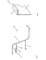
- Figure 1 shows a photovoltaic system 1 as a whole, made up according to a preferred embodiment of the present invention.
- the photovoltaic system 1 is shown in its assembled configuration on a surface S of a roof T, of which some roof tiles C are shown.
- the photovoltaic system 1 illustrated herein preferably comprises a plurality of modules 2, also called photovoltaic generators or, more commonly, solar panels.
- the solar panels 2 are eight and arranged side by side in two rows.
- the number and shape of said solar panels 2 can be any and will obviously depend on the type and size of the photovoltaic system, as well as on the space available for their installation.
- the photovoltaic system preferably comprises a plurality of solar panels arranged in several rows.
- Said panels 2 are preferably rectangular, meaning in particular that they have two main long sides 62 parallel to each other and two short sides 63 parallel to each other.
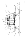
- the solar panels 2 are associated with each other through a modular structure 3 that substantially creates a supporting frame, as shown in Figure 2 .
- the modular structure 3 preferably comprises a plurality of first supporting elements with longitudinal development 4 suited to be arranged at the level of the long sides 62 of each solar panel 2 and in a lower position.
- Two adjacent panels 2 preferably share a first common element belonging to said first supporting elements 4.
- Each first supporting element 4 is associated, at its top, with a first closing element 5, suited to lock the peripheral edge of the long side 62 of the adjacent solar panel/s 2 against the underlying first supporting element 4.
- the first closing element 5 and the first supporting element 4 have a sealing gasket element 5a, 4a that extends over the entire length of the corresponding element 4, 5 at the level of the area of interface with the long side 62 of the solar panel 2.
- a first one of said sealing gasket elements 4a is accommodated in a seat 4b in the first supporting element 4.
- said seat 4b is constituted by a groove in the first supporting element 4.
- said groove 4b can be created during the production of the first supporting element 4 when this is obtained through an extrusion process.
- the second one of said sealing gasket elements 5a is accommodated in a seat 5b in the first closing element 5.
- said seat 5b is constituted by a groove in the first closing element 5.
- said groove 5b can be obtained during the production of the first closing element 5 when this is obtained through an extrusion process.
- the first closing element 5 is associated with the first supporting element 4 through suitable securing means, preferably constituted by screws 6 in the embodiment illustrated herein.
- said securing means can be made in any other manner suitable for the intended purpose.
- securing the first closing element 5 to the first supporting element 4 means fixing the solar panel 2 at the same time and obtaining the desired hydraulic seal through the sealing gasket elements 5a, 4a.
- the assembly of the photovoltaic system 1 of the invention does not require the use of sealing materials as occurs in the case of the installation techniques of the known type.
- connection base 7 is preferably associated with the underside of the first supporting element 4.
- connection base 7 has substantially the shape of an upturned U.
- connection base 7 advantageously comprises two coupling portions 8 constituted by respective shaped areas, the purpose of which is described in greater detail below.
- the coupling portion 8 preferably has a substantially rectangular cross section.
- the coupling portion 8 comprises an upper projection 9.
- connection base 7 In the final assembled configuration of the modular structure 3 the first supporting element 4 and the connection base 7 are integrally connected through suitable connection means, preferably constituted by screws 11 in the embodiment illustrated herein.
- connection means can be produced in any other manner suitable for the intended purpose.
- an intermediate layer 12 is advantagesouly interposed between the first supporting element 4 and the connection base 7.
- said intermediate layer 12 substantially occupies the entire area under each panel 2, thus creating an air space for waterproofing the surface S of the roof T against the external environment.
- said intermediate layer 12 comprises a transpiring waterproof sheath. Still advantageously, said intermediate layer 12 defines an insulating layer with low heat conductivity that attenuates the undesired effects of the thermal bridge along the first supporting element 4, thus guaranteeing better heat insulation between the external environment and the surface S of the roof T.
- connection base 7 and the first supporting element 4 are considerably reduced, thus reducing heat transmission towards the surface S of the roof T in summer or heat dispersion towards the outside in winter.
- the modular structure 3 then preferably comprises a plurality of second supporting elements with longitudinal development 18 suited to be arranged at the level of the short sides 63 of each panel 2 and in a lower position.
- Two adjacent panels 2 preferably share a second common element belonging to said second supporting elements 18.
- the second supporting elements 18 are arranged crosswise, in particular at right angles with respect to the first supporting elements 4.
- the second supporting elements 18 are connected at their end 69 to a projecting coupling portion 55 of the first supporting elements 4, as shown in Figure 4 .
- the second supporting elements 18 are connected to the projecting coupling portion 55 through screws.
- the first and the second supporting elements 4 and 18 substantially define a matrix supporting structure with rectangular areas for the overlying panels 2.
- each second supporting element 18 is associated, at its top, with a second closing element 19 suited to secure the peripheral edge of the short side 63 of the adjacent solar panel/s 2 against the underlying second supporting element 18.
- the peripheral edge of the short side 63 of the solar panel 2 is thus kept in a secured position between the second closing element 19 and the second supporting element 18.
- the second closing element 19 and the second supporting element 18 are provided with a sealing gasket element 19a, 18a that extends over the entire length of the corresponding element 18, 19 at the level of the area of interface with the short side 63 of the solar panel 2.
- the second closing element 19 is associated with the second supporting element 18 through suitable securing means, preferably constituted by screws 66 in the embodiment described herein.
- said securing means may be produced in any other manner suitable for the intended purpose.
- securing the second closing element 19 to the first supporting element 18 means fixing the solar panel 2 at the same time and obtaining the desired hydraulic seal through the sealing gasket elements 19a, 18a.
- the assembly of the photovoltaic system 1 of the invention does not require the use of sealing materials, as occurs in the case of the installation techniques of the known type.
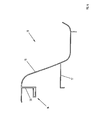
- Figure 3 shows a further element belonging to the photovoltaic system 1, and more particularly to the modular structure 3, consisting of a lateral drainage element 13 that is preferably positioned at the periphery of the photovoltaic system 1, as shown also in Figure 1 .
- the lateral drainage element 13 advantageously makes it possible to convey rainwater downwards, substantially acting as a gutter.
- the lateral drainage element 13 is preferably positioned on three sides of the modular structure 3 and thus of the photovoltaic system 1, meaning the upper side and the two lateral sides, where a rainwater drainage action is required.
- the underside of the modular structure 3 and thus of the photovoltaic system 1 is preferably associated with a further closing element 80, as is better described below and illustrated in Figure 10 .
- the lateral drainage element 13, better visible in Figure 6 preferably comprises a properly shaped drainage surface 15, a shaped fixing portion 14 and a contact element 17.
- the lateral drainage element 13 is closed as a package between the first closing element 5 and the underlying first supporting element 4, analogously to the situation illustrated with regard to the solar panels 2.
- the lateral drainage element 13 is closed as a package in its shaped portion 14 between the sealing gasket elements 5a, 4a of the first closing element 5 and of the first supporting element 4.
- securing the first closing element 5 to the first supporting element 4 means fixing the lateral drainage element 13 at the same time and obtaining the desired hydraulic seal through the sealing gasket elements 5a, 4a.
- the contact element 17 of the lateral drainage element 13 comes to be arranged in contact with the first supporting element 4 in order to guarantee good rigidity against any deformation to which the drainage surface 15 may be subjected due, for example, to the weight of rainwater or to the wind thrust force.
- the lateral drainage element 13 preferably comprises a vent 13a suited to allow the passage of air towards the underlying area that, in the assembled configuration of the photovoltaic system 1, is substantially closed.
- the vent 13a is preferably created in a wall 70 that extends vertically from the shaped fixing portion 14 to the drainage surface 15.
- the vent 13a of the lateral drainage element 13 allows the ventilation of said underlying closed area, avoiding the accumulation of humidity and the formation of mildew and/or moss.
- this extends the useful life of the elements of the photovoltaic system 1, of the modular supporting structure 3, of the waterproofing sheath 12, as well as of the solar panels 2.
- the first and the second supporting elements 4 and 18, the first and the second closing elements 5, 19, the connection base 7, the lateral drainage element 13 and the closing element 80 are structural elements.
- said structural elements are obtained through an extrusion process, more preferably through the extrusion of a metallic material, even more preferably of aluminium.
- the modular structure 3 is preferably fixed to the underlying surface S of the roof T through the use of a plurality of fixing elements 20.
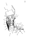
- FIG. 3 One of said fixing elements 20 according to a preferred embodiment is shown in Figure 3 and in Figure 4 .
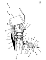
- Figure 5 it is possible to observe two of said fixing elements 20 in a particular operating configuration in the photovoltaic system 1.
- the number of fixing elements 20 used in the modular supporting structure 3 for the assembly of the photovoltaic system 1 depends on the number of solar panels 2 that make up the system 1. In particular, the number of fixing elements 20 depends on the number of first supporting elements 4 used for the assembly of the solar panels 2.
- each first supporting element 4 is associated with a first pair of fixing elements 20, as indicated for example in Figure 5
- the opposite terminal end of the first supporting element 4 is associated with a second pair of fixing elements 20.
- the fixing elements 20 used to fix the modular supporting structure 3 are all the same.
- the fixing element 20 comprises a first portion 21 suited to be connected to the underlying surface S of the roof T and a second portion 22 suited to be coupled with the overlying part of the photovoltaic system 1.
- the first portion 21 is associated with first fixing means 23 for connection to the surface S of the roof T.
- said first fixing means 23 comprise a through hole 24 suited to accommodate a fixing screw 25 that can be screwed onto the surface S of the roof T, preferably a Fisher® screw anchor.
- the second portion 22 is associated with second fixing means 26 for connection to the overlying part of the photovoltaic system 1.
- the second fixing means 26 allow connection to the modular structure 3 of the photovoltaic system 1.
- the second fixing means 26 allow connection to the connection base 7 of the modular structure 3.
- the second fixing means 26 preferably comprise a U-shaped area suited to be coupled with the coupling portion 8 of the connection base 7.
- the U-shaped area is snap-coupled with the coupling portion 8 of the connection base 7, with the upper projection 9 of the coupling portion 8 housed in a corresponding seat in the U-shaped area.
- connection and/or disconnection of the fixing element 20 to/from the connection base 7 are simplified and quick.
- the fixing element 20 is configured in such a way that the first portion 21 and the second portion 22 can be positioned as desired in different mutual positions.
- the positioning in different mutual positions is obtained through two articulation areas 30 and 31 defined along the route between the first portion 21 and the second portion 22.
- the two articulation areas 30 and 31 are defined at the ends of an intermediate articulation element 32 between the two portions 21, 22.
- the intermediate articulation element 32 preferably comprises two parallel articulation arms 32' and 32". In a variant embodiment of the invention, however, just one articulation arm may be provided.
- the first portion 21 and the second portion 22 of the fixing element 20 can thus assume different mutual operating positions, for example as shown in Figure 3 , where the first portion 21, the intermediate element 32 and the second portion 22 are substantially positioned at right angles with respect to each other or, as indicated in Figure 5 , said elements 21, 32, 22 are arranged mutually inclined with respect to each other.
- the fixing element 20 comprises securing means suited to maintain the mutual position defined between the first portion 21 and the second portion 22.
- the securing means are preferably provided at the level of the two articulation areas 30 and 31.
- the securing means preferably comprise a first screw 41 that is inserted through the first articulation arm 32', then in the first portion 21 and is engaged in a threaded hole in the second articulation arm 32".
- the package closure of the first screw 41 allows the first portion 21 and the intermediate articulation arm 32 to be mutually secured in the desired position.
- the securing means preferably comprise a second screw 51 that is inserted through the first articulation arm 32', then in the second portion 22 and is engaged in a threaded hole in the second articulation arm 32".
- the package closure of the second screw 51 allows the second portion 22 and the intermediate articulation arm 32 to be mutually secured in the desired position.
- the securing action obtained through said securing means is substantially defined by mechanical interference areas at the level of the articulation areas 30 and 31.
- the fixing system of the modular supporting structure 3 through the use of a plurality of fixing elements 20 represents one of the possible methods for fixing the modular supporting structure according to the invention.
- Figure 7 shows a variant embodiment of the photovoltaic system 100 according to the present invention.
- connection base 107 of the modular supporting structure 103 is made in a single body and is integral with the overlying first supporting element 104.
- Said embodiment makes it possible to reduce the construction complexity of the photovoltaic system 100 and to reduce the assembly operations, since actually it is not necessary to assemble the first supporting element onto the connection base as in the embodiment previously described.
- FIGS 8 and 9 show a different variant embodiment of the photovoltaic system 200 according to the present invention.
- Said embodiment of the photovoltaic system 200 differs from the one described above with reference to Figures from 1 to 6 due to the different shape of the lateral drainage element 213 of the modular supporting structure 203.
- the lateral drainage element 213 differs from the lateral drainage element 13 of the first embodiment of the invention in that the vent 213a is provided in a wall 270 that extends horizontally from the shaped fixing portion 14 to the drainage surface 15.
- Figure 10 shows a detail of the further closing element 80 of the modular supporting structure 3 of the photovoltaic system of the invention that, as previously explained, is arranged at the level of the lower side of the same system 1, as shown in Figure 1 .
- the closing element 80 together with the lateral drainage elements 13, advantageously makes it possible to close the space under the panels 2 in order to avoid the accumulation of undesired elements, like leaves or similar elements, or the entry of animals, usually birds.
- the closing element 80 preferably comprises a closing surface 81, preferably straight, and a shaped fixing portion 82.
- the closing element 80 is closed as a package between second closing elements 19 and underlying second supporting elements 18 of the modular supporting structure 3, analogously to the procedure described above for the solar panels 2 and the lateral drainage element 13.
- securing the second closing element 19 onto the first supporting element 18 means fixing the drainage element 80 at the same time and obtaining the desired hydraulic seal through the sealing gasket elements 19a, 18a.
- the closing surface 81 is solid.
- the closing surface 81 may advantageously comprise vents or, preferably, it may have a net-shaped structure. It has thus been proved that the present invention allows the set objects to be achieved. In particular, the invention makes it possible to provide a solar energy system in which the operations required for installation are simplified compared to those required in the systems of the known art.
Landscapes
- Engineering & Computer Science (AREA)
- Chemical & Material Sciences (AREA)
- Mechanical Engineering (AREA)
- Sustainable Development (AREA)
- Sustainable Energy (AREA)
- Thermal Sciences (AREA)
- Physics & Mathematics (AREA)
- Combustion & Propulsion (AREA)
- Life Sciences & Earth Sciences (AREA)
- General Engineering & Computer Science (AREA)
- Architecture (AREA)
- Civil Engineering (AREA)
- Structural Engineering (AREA)
- Photovoltaic Devices (AREA)
- Roof Covering Using Slabs Or Stiff Sheets (AREA)
Applications Claiming Priority (1)
| Application Number | Priority Date | Filing Date | Title |
|---|---|---|---|
| IT000205A ITVI20120205A1 (it) | 2012-08-07 | 2012-08-07 | Struttura modulare di supporto per un sistema ad energia solare. |
Publications (2)
| Publication Number | Publication Date |
|---|---|
| EP2696151A2 true EP2696151A2 (fr) | 2014-02-12 |
| EP2696151A3 EP2696151A3 (fr) | 2014-11-19 |
Family
ID=46939902
Family Applications (1)
| Application Number | Title | Priority Date | Filing Date |
|---|---|---|---|
| EP13003590.0A Withdrawn EP2696151A3 (fr) | 2012-08-07 | 2013-07-17 | Structure de support modulaire pour un système d'énergie solaire |
Country Status (2)
| Country | Link |
|---|---|
| EP (1) | EP2696151A3 (fr) |
| IT (1) | ITVI20120205A1 (fr) |
Cited By (2)
| Publication number | Priority date | Publication date | Assignee | Title |
|---|---|---|---|---|
| JP2017125343A (ja) * | 2016-01-14 | 2017-07-20 | ソーラーフロンティア株式会社 | 水切り板 |
| LU103350B1 (en) * | 2024-07-30 | 2026-01-30 | Iparlux S A R L | System and method for installation of solar panels on carports |
Families Citing this family (1)
| Publication number | Priority date | Publication date | Assignee | Title |
|---|---|---|---|---|
| US10673373B2 (en) | 2016-02-12 | 2020-06-02 | Solarcity Corporation | Building integrated photovoltaic roofing assemblies and associated systems and methods |
Family Cites Families (6)
| Publication number | Priority date | Publication date | Assignee | Title |
|---|---|---|---|---|
| JP4979665B2 (ja) * | 2008-09-29 | 2012-07-18 | シャープ株式会社 | 太陽電池装置 |
| ES2356763B1 (es) * | 2009-04-01 | 2012-03-20 | Producciones Mitjavila, S.A. | Sistema modular de fijación de paneles solares a una cubierta provisto de medios para canalizar el agua. |
| FR2949521A1 (fr) * | 2009-08-26 | 2011-03-04 | Actif En Vertes | Dispositif de fixation d'au moins un panneau sur une structure porteuse |
| FR2960625A1 (fr) * | 2010-05-26 | 2011-12-02 | Energysol | Dispositif de support etanche de panneaux solaires pour toutes toitures |
| FR2962797B1 (fr) * | 2010-07-19 | 2014-02-14 | Tenesol | Structure de montage d'un panneau de recuperation d'energie solaire sur un support, systeme comprenant une telle structure, installation comprenant un tel systeme, procede de montage d'un systeme de recuperation d'energie solaire sur un support |
| DE202011101279U1 (de) * | 2011-05-31 | 2011-07-26 | Siko Solar Gmbh | Vorrichtung zur Befestigung von Solarmodulen auf der Unterkonstruktion einer Dacheindeckung |
-
2012
- 2012-08-07 IT IT000205A patent/ITVI20120205A1/it unknown
-
2013
- 2013-07-17 EP EP13003590.0A patent/EP2696151A3/fr not_active Withdrawn
Non-Patent Citations (1)
| Title |
|---|
| None |
Cited By (3)
| Publication number | Priority date | Publication date | Assignee | Title |
|---|---|---|---|---|
| JP2017125343A (ja) * | 2016-01-14 | 2017-07-20 | ソーラーフロンティア株式会社 | 水切り板 |
| LU103350B1 (en) * | 2024-07-30 | 2026-01-30 | Iparlux S A R L | System and method for installation of solar panels on carports |
| EP4687286A1 (fr) * | 2024-07-30 | 2026-02-04 | Iparlux S.à.r.l. | Système et procédé d'installation de panneaux solaires sur des abris de voiture |
Also Published As
| Publication number | Publication date |
|---|---|
| EP2696151A3 (fr) | 2014-11-19 |
| ITVI20120205A1 (it) | 2014-02-08 |
Similar Documents
| Publication | Publication Date | Title |
|---|---|---|
| US11646692B2 (en) | Waterproofing mounting system for attaching solar modules to a roof | |
| JP2005517843A (ja) | 屋根板システム | |
| JP2005518486A (ja) | 屋根板システム及び方法 | |
| CN101166875A (zh) | 屋顶或立面覆层 | |
| JP2006500488A (ja) | 屋根板アセンブリ | |
| US20120312373A1 (en) | Solar Roof Panel Assembly and Method for Installation | |
| US6877287B2 (en) | Device with flat, panel-shaped components | |
| GB2466003A (en) | Securing A Solar Energy Collection Device As Part Of A Roof | |
| EP2696151A2 (fr) | Structure de support modulaire pour un système d'énergie solaire | |
| EP2886973A1 (fr) | Système photovoltaïque et procédé pour son installation | |
| GB2497276A (en) | Panel roofing frame with hook and click connection | |
| US20220416715A1 (en) | System for mounting tiles over a surface | |
| ITVI20120204A1 (it) | Elemento di fissaggio per sistemi ad energia solare e sistema comprendente tale elemento. |
Legal Events
| Date | Code | Title | Description |
|---|---|---|---|
| AK | Designated contracting states |
Kind code of ref document: A2 Designated state(s): AL AT BE BG CH CY CZ DE DK EE ES FI FR GB GR HR HU IE IS IT LI LT LU LV MC MK MT NL NO PL PT RO RS SE SI SK SM TR |
|
| AX | Request for extension of the european patent |
Extension state: BA ME |
|
| PUAI | Public reference made under article 153(3) epc to a published international application that has entered the european phase |
Free format text: ORIGINAL CODE: 0009012 |
|
| RIC1 | Information provided on ipc code assigned before grant |
Ipc: F24J 2/46 20060101ALI20140624BHEP Ipc: F24J 2/52 20060101AFI20140624BHEP Ipc: H01L 31/042 20140101ALI20140624BHEP |
|
| PUAL | Search report despatched |
Free format text: ORIGINAL CODE: 0009013 |
|
| AK | Designated contracting states |
Kind code of ref document: A3 Designated state(s): AL AT BE BG CH CY CZ DE DK EE ES FI FR GB GR HR HU IE IS IT LI LT LU LV MC MK MT NL NO PL PT RO RS SE SI SK SM TR |
|
| AX | Request for extension of the european patent |
Extension state: BA ME |
|
| RIC1 | Information provided on ipc code assigned before grant |
Ipc: H01L 31/042 20140101ALI20141016BHEP Ipc: F24J 2/52 20060101AFI20141016BHEP Ipc: F24J 2/46 20060101ALI20141016BHEP |
|
| STAA | Information on the status of an ep patent application or granted ep patent |
Free format text: STATUS: THE APPLICATION IS DEEMED TO BE WITHDRAWN |
|
| 18D | Application deemed to be withdrawn |
Effective date: 20150520 |