EP2696205A1 - Lecteur de microplaquettes avec lève-couvercle pour microplaquettes - Google Patents
Lecteur de microplaquettes avec lève-couvercle pour microplaquettes Download PDFInfo
- Publication number
- EP2696205A1 EP2696205A1 EP20130178313 EP13178313A EP2696205A1 EP 2696205 A1 EP2696205 A1 EP 2696205A1 EP 20130178313 EP20130178313 EP 20130178313 EP 13178313 A EP13178313 A EP 13178313A EP 2696205 A1 EP2696205 A1 EP 2696205A1
- Authority
- EP
- European Patent Office
- Prior art keywords
- microplate
- lid
- reader
- housing
- support
- Prior art date
- Legal status (The legal status is an assumption and is not a legal conclusion. Google has not performed a legal analysis and makes no representation as to the accuracy of the status listed.)
- Granted
Links
Images


Classifications
-
- G—PHYSICS
- G01—MEASURING; TESTING
- G01N—INVESTIGATING OR ANALYSING MATERIALS BY DETERMINING THEIR CHEMICAL OR PHYSICAL PROPERTIES
- G01N37/00—Details not covered by any other group of this subclass
-
- G—PHYSICS
- G01—MEASURING; TESTING
- G01N—INVESTIGATING OR ANALYSING MATERIALS BY DETERMINING THEIR CHEMICAL OR PHYSICAL PROPERTIES
- G01N21/00—Investigating or analysing materials by the use of optical means, i.e. using sub-millimetre waves, infrared, visible or ultraviolet light
- G01N21/62—Systems in which the material investigated is excited whereby it emits light or causes a change in wavelength of the incident light
- G01N21/63—Systems in which the material investigated is excited whereby it emits light or causes a change in wavelength of the incident light optically excited
- G01N21/64—Fluorescence; Phosphorescence
- G01N21/6428—Measuring fluorescence of fluorescent products of reactions or of fluorochrome labelled reactive substances, e.g. measuring quenching effects, using measuring "optrodes"
-
- G—PHYSICS
- G01—MEASURING; TESTING
- G01N—INVESTIGATING OR ANALYSING MATERIALS BY DETERMINING THEIR CHEMICAL OR PHYSICAL PROPERTIES
- G01N21/00—Investigating or analysing materials by the use of optical means, i.e. using sub-millimetre waves, infrared, visible or ultraviolet light
-
- G—PHYSICS
- G01—MEASURING; TESTING
- G01N—INVESTIGATING OR ANALYSING MATERIALS BY DETERMINING THEIR CHEMICAL OR PHYSICAL PROPERTIES
- G01N35/00—Automatic analysis not limited to methods or materials provided for in any single one of groups G01N1/00 - G01N33/00; Handling materials therefor
-
- G—PHYSICS
- G01—MEASURING; TESTING
- G01N—INVESTIGATING OR ANALYSING MATERIALS BY DETERMINING THEIR CHEMICAL OR PHYSICAL PROPERTIES
- G01N35/00—Automatic analysis not limited to methods or materials provided for in any single one of groups G01N1/00 - G01N33/00; Handling materials therefor
- G01N35/02—Automatic analysis not limited to methods or materials provided for in any single one of groups G01N1/00 - G01N33/00; Handling materials therefor using a plurality of sample containers moved by a conveyor system past one or more treatment or analysis stations
- G01N35/028—Automatic analysis not limited to methods or materials provided for in any single one of groups G01N1/00 - G01N33/00; Handling materials therefor using a plurality of sample containers moved by a conveyor system past one or more treatment or analysis stations having reaction cells in the form of microtitration plates
-
- G—PHYSICS
- G01—MEASURING; TESTING
- G01N—INVESTIGATING OR ANALYSING MATERIALS BY DETERMINING THEIR CHEMICAL OR PHYSICAL PROPERTIES
- G01N35/00—Automatic analysis not limited to methods or materials provided for in any single one of groups G01N1/00 - G01N33/00; Handling materials therefor
- G01N35/02—Automatic analysis not limited to methods or materials provided for in any single one of groups G01N1/00 - G01N33/00; Handling materials therefor using a plurality of sample containers moved by a conveyor system past one or more treatment or analysis stations
- G01N35/04—Details of the conveyor system
-
- G—PHYSICS
- G01—MEASURING; TESTING
- G01N—INVESTIGATING OR ANALYSING MATERIALS BY DETERMINING THEIR CHEMICAL OR PHYSICAL PROPERTIES
- G01N35/00—Automatic analysis not limited to methods or materials provided for in any single one of groups G01N1/00 - G01N33/00; Handling materials therefor
- G01N2035/00178—Special arrangements of analysers
- G01N2035/00277—Special precautions to avoid contamination (e.g. enclosures, glove- boxes, sealed sample carriers, disposal of contaminated material)
- G01N2035/00287—Special precautions to avoid contamination (e.g. enclosures, glove- boxes, sealed sample carriers, disposal of contaminated material) movable lid/cover for sample or reaction tubes
-
- G—PHYSICS
- G01—MEASURING; TESTING
- G01N—INVESTIGATING OR ANALYSING MATERIALS BY DETERMINING THEIR CHEMICAL OR PHYSICAL PROPERTIES
- G01N35/00—Automatic analysis not limited to methods or materials provided for in any single one of groups G01N1/00 - G01N33/00; Handling materials therefor
- G01N35/02—Automatic analysis not limited to methods or materials provided for in any single one of groups G01N1/00 - G01N33/00; Handling materials therefor using a plurality of sample containers moved by a conveyor system past one or more treatment or analysis stations
- G01N35/04—Details of the conveyor system
- G01N2035/0401—Sample carriers, cuvettes or reaction vessels
- G01N2035/0403—Sample carriers with closing or sealing means
- G01N2035/0405—Sample carriers with closing or sealing means manipulating closing or opening means, e.g. stoppers, screw caps, lids or covers
-
- Y—GENERAL TAGGING OF NEW TECHNOLOGICAL DEVELOPMENTS; GENERAL TAGGING OF CROSS-SECTIONAL TECHNOLOGIES SPANNING OVER SEVERAL SECTIONS OF THE IPC; TECHNICAL SUBJECTS COVERED BY FORMER USPC CROSS-REFERENCE ART COLLECTIONS [XRACs] AND DIGESTS
- Y10—TECHNICAL SUBJECTS COVERED BY FORMER USPC
- Y10S—TECHNICAL SUBJECTS COVERED BY FORMER USPC CROSS-REFERENCE ART COLLECTIONS [XRACs] AND DIGESTS
- Y10S436/00—Chemistry: analytical and immunological testing
- Y10S436/807—Apparatus included in process claim, e.g. physical support structures
Definitions
- the invention relates to a Deckelabheber for microplates, which is installed in a microplate reader with at least one optical measuring / detecting device.
- microplates allow biological or biochemical experiments to be performed in which a large number of samples are processed in parallel.
- Microplate readers have proven themselves many times in the optical evaluation of test results obtained in microplates.
- microplates As a microplate in the context of the present invention, all multiwell plates are referred to, which have a plurality of wells or containers, which are arranged in an array. Specifically preferred microplates have at least approximately the mass and footprint of a SBS standard microplate as published by the American National Standards Institute (ANSI). For example, microplates whose wells are equipped with a round bottom, flat bottom or V-bottom are known. The wells may be designed as "normal wells" or as "deep wells”. Also frustoconical or truncated pyramidal wells are known per se.
- microplates with a wide variety of corrugations have in common that they have a normalized footprint, ie a standardized footprint, and that the axial spacing of the corrugations arranged in an array is also standardized, for example at 24-wells (4 ⁇ 6). Plates 18 mm, 96 mm (8 x 12) plates 9 mm, 384-well (16 x 24) plates 4.5 mm and 1536-well (32 x 48) plates 2.25 mm
- the height of a microplate may vary depending on Type vary greatly and is typically between 10.4 mm (eg 1536 V soil deep well plate) and 44 mm (eg 96 well Masterblock ® Greiner).
- microplates When biological or biochemical experiments are carried out in microplates over a prolonged period of time (during hours or even days) and / or elevated temperatures, often and typically evaporation occurs, resulting in a decrease in the volume and concentration of electrolytes and macromolecules until the solids dry Can lead samples. For this reason, the microplates are preferably processed in a separate incubator, wherein temperature and humidity are controlled so that no evaporation takes place.
- the disadvantage here is that the microplates for measurements manually between incubator and reader back and forth must be transferred.
- the document EP 1 192 995 A2 discloses a special sealable lid for standard microplates and a robotic gripper for holding the microplate and repeatedly removing and replacing this special lid.
- the lid exerts a spring pressure on the seal so that it seals against the microplate.
- this special lid construction of the robot gripper is designed to release the resilient parts of the lid and constructed quite complicated.
- this microplate reader comprises at least one optical measuring / detecting device, a housing, a microplate support and a moving unit.
- the moving unit is for moving the microplate seat out of the housing into which
- the microplate reader according to the invention is characterized in that it comprises an integrated cover holding device arranged inside the housing for lifting a microplate cover from a microplate positioned on the microplate support and for placing a microplate cover on a microplate, this cover holding device for moving the microplate cover and / or the microplate support is designed to move the microplate in each case in an at least approximately vertical direction.
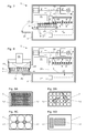
- FIG. 1 shows a vertical section through a microplate reader 1 with extended movement unit 5 and microplate support 4, after manually or robotically positioning a covered microplate 8 on the microplate support 4.
- the microplate reader 1 comprises a controller 21 for monitoring and controlling the functions of the reader and the movement unit 5.
- the microplate reader 1 shown here comprises at least one optical measuring / detecting device 2.
- the microplate reader 1 also comprises a housing 3, a microplate seat 4 and a moving unit 5, wherein the moving unit 5 for moving the microplate seat 4 out of the housing 3 is formed into the housing 3 and within the housing 3 in at least one substantially horizontal direction.
- the housing 3 is preferably optically sealed from the environment.
- the housing can also be insulated with respect to the temperature, the gas composition and their relative humidity from the environment and thus formed as a climate chamber.
- This optical measuring / detection device 2 can also be referred to as a "measuring head” and fixed in place, ie immovably arranged, in which case the movement unit 5 is additionally designed to be vertically movable for focusing the optical measuring / detecting device 2.
- a further alternative comprises forming a height-adjustable optical measuring / detecting device 2 and a height-adjustable moving unit 5, and then focusing the optical measuring / detecting device 2 preferably with the measuring head 2 with a fine Z-drive equipped for focusing the optical measuring / detecting device t.
- the microplate reader 1 also comprises an integrated cover holding device 6 arranged inside the housing 3 for lifting a microplate cover 7 from a microplate 8 positioned on the microplate support 4 and for placing a microplate cover 7 on a microplate 8.
- the cover holding device 6 is designed to lift one Microplate cover 7 from a microplate 8 positioned on the microplate support 4, for holding this microplate cover 7 during the optical measurement of the microplate 8 and for placing the same microplate cover 7 on the same microplate 8.
- the lid holding device 6 is formed such that with it the microplate lid 7 can be stored during the measurement of the microplate 8 within the housing 3 of the microplate reader 1.
- the cover holding device 6 and / or the microplate support 4 may each be formed in an at least approximately vertical direction.
- the microplate lid 7 is lifted from the microplate 8 or the microplate 8 is lowered relative to the microplate lid 7.
- a third possibility is to move the microplate cover 7 and the microplate 8 apart.
- exemplary microplate reader 1 comprises a lid holding device 6, which is designed as a magnetic lifter 6 '.
- This lid holding device 6 comprises an array of permanent magnets 9.
- This lid holding device 6 is fastened here with bending-elastic or limp elements 22 on a carrying device 17.
- These flexurally elastic or limp elements 22 are (as shown) preferably mounted so that their mounting locations on the support device 17 are further apart than their mounting locations on the magnetic lifter 6 '. This arrangement automatically gives an effective self-centering of the magnetic lifter 6 'and also efficiently dampens its natural vibration.
- the support device 17 must be designed accordingly expansive.
- These flexurally elastic or limp elements 22 are preferably designed as metal-comprising lines or cords.
- the supporting device 17 shown is designed to be adjustable in height, with any movements are indicated in each case with a directional arrow and a "Z".
- the lid holding device 6 may comprise an electromagnetic array 10 (not shown) or a single, switchable permanent magnet 11 (see FIG. Fig. 10 ).
- each microplate lid 7 to be lifted and set up comprises magnetizable material 12.
- the magnetizable material 12 is selected from a group comprising self-adhesive metal foils, applied metallic paints, molded metallic splinters or metallic grains, as well as plastic-coated or back-injected metal plates or metal foils.
- the metals are preferably selected from the group comprising iron, nickel, cobalt and their alloys and alloys of these metals with non-magnetizable metals.
- the in Fig. 1 shown exemplary microplate reader 1 also comprises a substantially horizontally disposed optical axis 23 and a substantially vertically arranged detection axis 24.
- this microplate reader 1 Located on the optical axis 23 and above the movement unit 5 with the microplate overlay 4, this microplate reader 1 comprises a detection optics second ', a light source L and a first excitation optical system 2 ".
- this microplate reader 1 comprises a second excitation optical system 2"' which is arranged below the movement unit 5 with the microplate support 4 and on the detection axis 24.
- the measuring head 2, ie the optical measuring / detection device is arranged.
- the individual optical elements 2, 2 ', 2 ", 2"' are preferably connected to one another by means of optical glass fibers, which is schematically indicated here by dash-dotted lines (without necessarily indicating the best or actual connection path).
- a door 20 has been opened here in a downward opening.
- a laterally displaceable door 20 may be provided (not shown).
- This alternative arrangement of the open door 20 facilitates the picking up of a microplate to be processed from a transfer station 37 placed in front of the door 20 (cf. Fig. 11 ).
- This alternative arrangement of the open door 20 also facilitates dispensing an already processed microplate to this transfer station 37 placed in front of the door 20 (see FIG. Fig. 11 ).
- Another alternative arrangement of the open door is, for example, that the door 20 made as a flap retracts to open under the plate transport to open.
- the deposition of the microplate 8 on the microplate support 4 or the picking up of the microplate 8 from the microplate support 4 can also be done manually, as shown by a robot 18 equipped with gripper fingers 19.
- the lid holding device 6 can be designed as suction cup lifter 6 "(not shown) and comprises at least one suction cup 14 which can be connected to a vacuum source 13.
- This vacuum source 13 is preferably arranged in the housing 3 of the microplate reader 1, but it can for example, be arranged outside of the microplate reader 1 for reasons of space.
- the lid holding device 6 may be designed as a gripper 6 '"(not shown) and comprises at least two gripper fingers 15 for loading side surfaces 16 of a microplate lid 7.
- the lid holding device 6 is designed to carry out a lifting and lowering movement.
- the lid holding device 6 is arranged immovable immovable, but then the moving unit 5 must be designed to carry out a lifting and lowering movement of the microplate seat 4.
- the optical measuring / detection device 2 that is to say the measuring head 2 is arranged immovably in place. It is also preferable to form the moving unit 5 for performing movements of the microplate base 4 in the X, Y, and Z directions of a Cartesian coordinate system.
- a measuring method in which, between the lifting of the microplate cover 7 from the microplate 8 positioned on the microplate support 4 according to step c) and the optical measurement of the microplate 8 with the microplate cover 7 lifted off with the at least one optical measuring / detection device 2 according to step d), the samples in the wells 25 of the microplate 8 with Air and / or be contacted with a reagent for triggering luminescence or other reactions.
- the inventive lifting and reassembly of the microplate cover 7 inside the microplate reader 1 - possibly in combination with a designed as a climate chamber sample space inside the microplate reader 1 - allows performing long-term experiments and monitoring the long-term kinetics (eg growth) of cell cultures in the wells 25 of microplates 8.
- the sporadically and repeatedly performed optical measurements on the samples are made possible by a brief lifting and reassembly of the microplate lid 7.
- adding nutrient medium or other substances and agents to the cell cultures in the wells 25 of microplates 8 is facilitated by briefly lifting and replacing the microplate lid 7.
- Such long-term tests are preferably carried out in standalone microplate readers 1.
- the microplate lid 7 after the optical measurement of the microplate 8 using the lid holding device 6 within the housing 3 of the microplate reader 1 placed on the microplate 8 and the microplate overlay 4 and the covered microplate 8 with the movement unit. 5 is conveyed out of the housing 3 of the microplate reader 1.
- this displacement problem can be solved by using an array of permanent magnets 9 instead of the single magnet (as shown).
- this displacement problem can be solved by the fact that the individual magnet of the magnetic lifter 6 'and the magnetizable material 12 are mounted exactly in projection one above the other.
- the cover holding device 6 instead of a magnetic lifter 6 'a plate of a magnetizable material (eg, iron, nickel or cobalt or from at least one of these metals comprehensive metal alloy), said plate preferably has a surface which is larger than the surface of the male microplate cover 7 (not shown). It then suffices for example to fasten a magnetic material (eg a magnetic foil or a single one) Permanent magnet) on the microplate cover (not shown).
- the lid holding device 6 may comprise a magnetizable material 12 selected from a group comprising self-adhering metal foils, applied metallic paints, molded metallic chips or grains, as well as plastic-molded or back-injected metal plates or metal foils.
- FIG. 10 shows a 3D view of the moving unit 5 with a microplate 8 positioned on the microplate support 4 with the microplate cover 7 mounted with side surfaces 16 and a magnetizable material 12.
- the Cartesian coordinate system is indicated by the three arrows (X, Y and Z).
- the movement unit 5 comprises two parallel guide rods 27 on each of which a sliding bearing 30 is movably arranged. These two plain bearings 30 are connected to each other via a carriage 36.
- a first motor 26 moves this carriage 36 in an X direction of a Cartesian coordinate system with a first toothed belt guided over a first guide roller 29.
- the microplate support 4 is attached to this carriage 36 by means of a link 33, said link 33 being movably guided along a linear guide 32 and along the carriage 36.
- a second motor 31 moves the link 33 with the microplate rest 4 in a Y direction of the Cartesian coordinate system by means of a second toothed belt 34 guided via a second deflecting roller 35.
- the moving device 5 just described is preferably movable in a Z direction of the Cartesian coordinate system (not shown) in Fig. 10 ).
- FIG. 10 also shows a lid holding device 6 with a magnetic lifter 6 ', which comprises a single, switchable permanent magnet 11.
- Switchable permanent magnets are known from the prior art (cf., for example EP 0 114 259 B1 ) and are adapted by a person skilled in the knowledge of the present invention in their construction and arrangement the requirements for lifting a microplate cover 7.
- lid holding device 6 instead of the lid holding device 6 with a magnetic lifter 6 ', a person skilled in the art could readily provide a lid holding device 6 which is designed as a suction cup lifter 6 "or as a gripper 6'", wherein it requires a raising and lowering motion as needed the lid holding device 6 would coordinate with movements of the moving unit 5 to perform movements of the microplate rest 4 in the X, Y, and Z directions of a Cartesian coordinate system.
- FIG. 11 shows a slightly enlarged 3D view of the empty microplate support 4 of the movement unit 5 (corresponding to the Fig. 10 ) at a transfer station 37 and in the corresponding magnification, a 3D view of a 96-well microplate 8 without microplate lid 7.
- the transfer station 37 comprises a support plate 38 with a microplate 4 adapted shape, wherein the microplate support 4 has cutouts 39 which extend beyond the Footprint 40 a standard microplate 8 go out, so that parts of the support plate 38, which extend into these cutouts 39 enough to support the microplate 8 suffice.
- the microplate receptacle 4 of the movement unit 5 is extended at a Z level below the level of the support plate 38 of the transfer station 37 and thus also below the footprint 40 of the microplate 8 on this support plate 38.
- the microplate holder 4 is raised in the Z direction until the microplate 8 lies on the microplate holder 4.
- the large section 39 in the support plate 38 very low in the FIG. 11 ) starting the transfer station 37 at a lower level than the surface of the support plate, if this support plate 38 by a central post (not shown) on a working surface of a laboratory workstation (not shown) should be supported.
- the microplate receptacle 4 of the movement unit 5 is extended in a Z-level which is above the level of the support plate 38 of the transfer station 37. After taking a correct transfer position, the microplate receptacle 4 is lowered in the Z direction until the microplate 8 lies on the support plate 38 of the transfer station 37.
Landscapes
- Chemical & Material Sciences (AREA)
- Health & Medical Sciences (AREA)
- Physics & Mathematics (AREA)
- Immunology (AREA)
- Analytical Chemistry (AREA)
- Biochemistry (AREA)
- General Health & Medical Sciences (AREA)
- General Physics & Mathematics (AREA)
- Life Sciences & Earth Sciences (AREA)
- Pathology (AREA)
- Chemical Kinetics & Catalysis (AREA)
- Optics & Photonics (AREA)
- Nuclear Medicine, Radiotherapy & Molecular Imaging (AREA)
- Automatic Analysis And Handling Materials Therefor (AREA)
- Investigating Or Analysing Materials By Optical Means (AREA)
- Optical Measuring Cells (AREA)
- Investigating, Analyzing Materials By Fluorescence Or Luminescence (AREA)
Priority Applications (1)
| Application Number | Priority Date | Filing Date | Title |
|---|---|---|---|
| EP16169209.0A EP3073269B1 (fr) | 2012-08-09 | 2013-07-29 | Lecteur de micro-plaquettes avec leve-couvercle pour micro-plaquettes |
Applications Claiming Priority (1)
| Application Number | Priority Date | Filing Date | Title |
|---|---|---|---|
| CH01306/12A CH706811A1 (de) | 2012-08-09 | 2012-08-09 | Mikroplatten-Reader mit Deckelabheber für Mikroplatten. |
Related Child Applications (2)
| Application Number | Title | Priority Date | Filing Date |
|---|---|---|---|
| EP16169209.0A Division-Into EP3073269B1 (fr) | 2012-08-09 | 2013-07-29 | Lecteur de micro-plaquettes avec leve-couvercle pour micro-plaquettes |
| EP16169209.0A Division EP3073269B1 (fr) | 2012-08-09 | 2013-07-29 | Lecteur de micro-plaquettes avec leve-couvercle pour micro-plaquettes |
Publications (2)
| Publication Number | Publication Date |
|---|---|
| EP2696205A1 true EP2696205A1 (fr) | 2014-02-12 |
| EP2696205B1 EP2696205B1 (fr) | 2016-09-28 |
Family
ID=47632636
Family Applications (2)
| Application Number | Title | Priority Date | Filing Date |
|---|---|---|---|
| EP16169209.0A Active EP3073269B1 (fr) | 2012-08-09 | 2013-07-29 | Lecteur de micro-plaquettes avec leve-couvercle pour micro-plaquettes |
| EP13178313.6A Active EP2696205B1 (fr) | 2012-08-09 | 2013-07-29 | Lecteur de plaque microtitre avec lève-couvercle pour plaques microtitres |
Family Applications Before (1)
| Application Number | Title | Priority Date | Filing Date |
|---|---|---|---|
| EP16169209.0A Active EP3073269B1 (fr) | 2012-08-09 | 2013-07-29 | Lecteur de micro-plaquettes avec leve-couvercle pour micro-plaquettes |
Country Status (6)
| Country | Link |
|---|---|
| US (1) | US9029101B2 (fr) |
| EP (2) | EP3073269B1 (fr) |
| JP (1) | JP6173821B2 (fr) |
| KR (1) | KR20140021488A (fr) |
| CN (1) | CN103575653B (fr) |
| CH (1) | CH706811A1 (fr) |
Cited By (4)
| Publication number | Priority date | Publication date | Assignee | Title |
|---|---|---|---|---|
| DE202014105173U1 (de) | 2013-11-07 | 2015-02-10 | Tecan Trading Ag | Inkubationskassette |
| CN104859949A (zh) * | 2014-02-26 | 2015-08-26 | 泰肯贸易股份公司 | 用于转运实验室物品的转运工具 |
| US11009457B2 (en) | 2017-09-01 | 2021-05-18 | Ushio Denki Kabushiki Kaisha | Microplate reader |
| CN115405823A (zh) * | 2022-09-09 | 2022-11-29 | 深圳鸣基医疗科技有限公司 | 微板支架及微板组件 |
Families Citing this family (16)
| Publication number | Priority date | Publication date | Assignee | Title |
|---|---|---|---|---|
| US11041871B2 (en) * | 2014-04-16 | 2021-06-22 | Bd Kiestra B.V. | System and method for incubation and reading of biological cultures |
| EP3035060B1 (fr) * | 2014-12-18 | 2017-09-06 | F. Hoffmann-La Roche AG | Procédé et dispositif de manipulation d'un élément de fermeture dans un système d'automatisation de laboratoire |
| CN104535760B (zh) * | 2014-12-31 | 2016-08-24 | 重庆科斯迈生物科技有限公司 | 化学发光免疫分析仪检测箱 |
| EP3314269A4 (fr) | 2015-06-26 | 2019-01-23 | Abbott Laboratories | Dispositif d'échangeur de cuve de réaction pour un analyseur de diagnostic |
| EP3171150A1 (fr) * | 2015-11-17 | 2017-05-24 | ETH Zürich | Procédé, dispositif et système pour la manipulation de parties d'un corps rigide |
| CN105527450B (zh) * | 2015-12-31 | 2017-11-03 | 中国科学院苏州生物医学工程技术研究所 | 一种用于全自动检测仪器的微孔板传送装置 |
| US11975330B2 (en) * | 2017-01-31 | 2024-05-07 | Myriad Women's Health, Inc. | Devices for handling laboratory plates and methods of using the same |
| JP6877531B2 (ja) * | 2017-03-28 | 2021-05-26 | 株式会社日立ハイテク | 検査装置 |
| US10260033B1 (en) | 2017-10-06 | 2019-04-16 | Wyatt Technology Corporation | Method and apparatus to mitigate evaporation in high throughput measurements |
| KR102101552B1 (ko) * | 2018-05-31 | 2020-04-16 | 전자부품연구원 | 형광 광학 모듈 |
| EP3839481B1 (fr) * | 2019-12-20 | 2025-02-26 | Tecan Trading Ag | Procédé de réduction de l'évaporation de liquide à partir de puits d'une microplaque |
| CN112162093B (zh) * | 2020-11-20 | 2023-12-29 | 山东畜牧兽医职业学院 | 用于微生物耐药试验的酶标仪 |
| DE102021203877A1 (de) * | 2021-04-19 | 2022-10-20 | Dispendix Gmbh | Ausfahrmechanismus und Bearbeitungsvorrichtung |
| KR102522278B1 (ko) | 2021-10-29 | 2023-04-17 | 주식회사 신코 | 듀얼 어레이 센서를 이용한 고속 흡광도 측정 마이크로플레이트 리더기 |
| EP4630582A1 (fr) | 2022-12-08 | 2025-10-15 | Becton, Dickinson and Company | Systèmes de dpcr entièrement automatisés et leurs procédés d'utilisation |
| EP4574260B1 (fr) | 2023-12-22 | 2026-03-18 | Tecan Trading AG | Appareil de traitement de microplaques et procédé de placement de couvercle à l'aide de l'appareil |
Citations (8)
| Publication number | Priority date | Publication date | Assignee | Title |
|---|---|---|---|---|
| EP0114259B1 (fr) | 1982-12-23 | 1986-02-12 | Werkzeugmaschinenfabrik Oerlikon-Bührle AG | Switchable permanent magnet |
| WO1993008914A1 (fr) * | 1991-10-31 | 1993-05-13 | Baxter Diagnostics, Inc. | Systemes d'analyse et de traitement d'echantillons comprenant un dispositif servant a contenir des plateaux d'echantillons au cours du traitement |
| EP1192995A2 (fr) | 2000-09-29 | 2002-04-03 | Becton Dickinson and Company | Plaque à plusieurs trous et arrangement pour la manipulation mécanique |
| DE20101734U1 (de) * | 2001-02-01 | 2002-06-13 | EVOTEC BioSystems AG, 22525 Hamburg | Probenträger |
| US6449827B1 (en) | 1999-10-22 | 2002-09-17 | Merck & Co., Inc | Apparatus for gripping microplates |
| EP1640723A1 (fr) * | 2004-04-07 | 2006-03-29 | Matsushita Electric Industries Co., Ltd. | Dispositif de traitement de microplaques et procédé de transport de microplaques |
| US7666362B2 (en) | 2004-03-31 | 2010-02-23 | Becton, Dickinson And Company | Micro-plate and lid for robotic handling |
| US20110293488A1 (en) | 2007-01-12 | 2011-12-01 | Nichols Michael J | Apparatus for lidding or delidding microplate |
Family Cites Families (7)
| Publication number | Priority date | Publication date | Assignee | Title |
|---|---|---|---|---|
| JPS51117360U (fr) * | 1974-07-18 | 1976-09-22 | ||
| US6229422B1 (en) * | 1998-04-13 | 2001-05-08 | Walker Magnetics Group, Inc. | Electrically switchable magnet system |
| DE10049491A1 (de) * | 2000-10-06 | 2002-04-11 | Mettler Toledo Gmbh | Analysenvorrichtung und Probendeckel |
| EP1670945A2 (fr) * | 2003-09-19 | 2006-06-21 | Applera Corporation | Microplaques utilisees pour effectuer une amplification nucleotidique par cyclage thermique |
| US7695688B2 (en) * | 2003-09-19 | 2010-04-13 | Applied Biosystems, Llc | High density plate filler |
| CN201110816Y (zh) * | 2007-12-18 | 2008-09-03 | 华南理工大学 | 一种用于光学监测空气中污染物的半自动实验配气装置 |
| JP5303521B2 (ja) * | 2010-07-27 | 2013-10-02 | 株式会社日立ハイテクノロジーズ | 核酸検査装置 |
-
2012
- 2012-08-09 CH CH01306/12A patent/CH706811A1/de unknown
-
2013
- 2013-07-29 EP EP16169209.0A patent/EP3073269B1/fr active Active
- 2013-07-29 EP EP13178313.6A patent/EP2696205B1/fr active Active
- 2013-08-01 JP JP2013160553A patent/JP6173821B2/ja active Active
- 2013-08-01 US US13/956,551 patent/US9029101B2/en active Active
- 2013-08-07 KR KR20130093596A patent/KR20140021488A/ko not_active Withdrawn
- 2013-08-09 CN CN201310435521.5A patent/CN103575653B/zh active Active
Patent Citations (8)
| Publication number | Priority date | Publication date | Assignee | Title |
|---|---|---|---|---|
| EP0114259B1 (fr) | 1982-12-23 | 1986-02-12 | Werkzeugmaschinenfabrik Oerlikon-Bührle AG | Switchable permanent magnet |
| WO1993008914A1 (fr) * | 1991-10-31 | 1993-05-13 | Baxter Diagnostics, Inc. | Systemes d'analyse et de traitement d'echantillons comprenant un dispositif servant a contenir des plateaux d'echantillons au cours du traitement |
| US6449827B1 (en) | 1999-10-22 | 2002-09-17 | Merck & Co., Inc | Apparatus for gripping microplates |
| EP1192995A2 (fr) | 2000-09-29 | 2002-04-03 | Becton Dickinson and Company | Plaque à plusieurs trous et arrangement pour la manipulation mécanique |
| DE20101734U1 (de) * | 2001-02-01 | 2002-06-13 | EVOTEC BioSystems AG, 22525 Hamburg | Probenträger |
| US7666362B2 (en) | 2004-03-31 | 2010-02-23 | Becton, Dickinson And Company | Micro-plate and lid for robotic handling |
| EP1640723A1 (fr) * | 2004-04-07 | 2006-03-29 | Matsushita Electric Industries Co., Ltd. | Dispositif de traitement de microplaques et procédé de transport de microplaques |
| US20110293488A1 (en) | 2007-01-12 | 2011-12-01 | Nichols Michael J | Apparatus for lidding or delidding microplate |
Cited By (10)
| Publication number | Priority date | Publication date | Assignee | Title |
|---|---|---|---|---|
| DE202014105173U1 (de) | 2013-11-07 | 2015-02-10 | Tecan Trading Ag | Inkubationskassette |
| CN104859949A (zh) * | 2014-02-26 | 2015-08-26 | 泰肯贸易股份公司 | 用于转运实验室物品的转运工具 |
| CN104858003A (zh) * | 2014-02-26 | 2015-08-26 | 泰肯贸易股份公司 | 用于转运实验室物品的转运工具 |
| EP2913678A1 (fr) * | 2014-02-26 | 2015-09-02 | Tecan Trading AG | Outil de transport destiné au transport d'un article de laboratoire |
| US10065325B2 (en) | 2014-02-26 | 2018-09-04 | Tecan Trading Ag | Transport tool for transporting a laboratory article |
| CN104859949B (zh) * | 2014-02-26 | 2019-06-28 | 泰肯贸易股份公司 | 用于转运实验室物品的转运工具 |
| CN104858003B (zh) * | 2014-02-26 | 2019-09-03 | 泰肯贸易股份公司 | 用于转运实验室物品的转运工具 |
| US11167424B2 (en) | 2014-02-26 | 2021-11-09 | Tecan Trading Ag | Transport tool for transporting a laboratory article |
| US11009457B2 (en) | 2017-09-01 | 2021-05-18 | Ushio Denki Kabushiki Kaisha | Microplate reader |
| CN115405823A (zh) * | 2022-09-09 | 2022-11-29 | 深圳鸣基医疗科技有限公司 | 微板支架及微板组件 |
Also Published As
| Publication number | Publication date |
|---|---|
| US9029101B2 (en) | 2015-05-12 |
| EP2696205B1 (fr) | 2016-09-28 |
| JP6173821B2 (ja) | 2017-08-02 |
| US20140045210A1 (en) | 2014-02-13 |
| KR20140021488A (ko) | 2014-02-20 |
| EP3073269B1 (fr) | 2020-01-01 |
| CH706811A1 (de) | 2014-02-14 |
| JP2014041121A (ja) | 2014-03-06 |
| CN103575653B (zh) | 2018-11-09 |
| CN103575653A (zh) | 2014-02-12 |
| EP3073269A1 (fr) | 2016-09-28 |
Similar Documents
| Publication | Publication Date | Title |
|---|---|---|
| EP2696205B1 (fr) | Lecteur de plaque microtitre avec lève-couvercle pour plaques microtitres | |
| EP2816103B1 (fr) | Dispositif de manipulation de boîtes de pétri | |
| EP2384363A2 (fr) | Installation pour la culture automatisée et parallèle de cellules | |
| US9993824B2 (en) | Microplate reader with lid lifter for microplates | |
| EP3705889B1 (fr) | Dispositif d'examen d' ufs | |
| DE102010053913A1 (de) | Verfahren zum Separieren und Detektieren eines Analyten | |
| WO2014079725A1 (fr) | Appareillage et procédé de fabrication d'éléments électrochimiques | |
| WO2012028519A1 (fr) | Dispositif et procédé permettant d'isoler et de transférer automatiquement au moins un échantillon microscopique d'un porte-échantillons à un système récepteur | |
| DE102020102758A1 (de) | Verfahren und System zum automatisierten Keimmonitoring in einem Isolator | |
| EP3436832B1 (fr) | Dispositif de transport | |
| DE102007042138A1 (de) | Verfahren und Einrichtung zur automatischen Probenzuführung | |
| US9568414B2 (en) | Microplate reader with lid lifter for microplates | |
| DE10239739B4 (de) | Vorrichtung und Verfahren zur Durchführung von immunologischen Markierungstechniken für Gewebedünnschnitte | |
| EP1291647B1 (fr) | Dispositif de préhension magnétique pour changer des échantillons allongés dans un analysateur à rayons X | |
| DE102015100637B4 (de) | Vorrichtung zum automatischen Durchführen chemischer und biologischer Verfahren in Gefäßplatten | |
| EP1291648B1 (fr) | Boîtier à encombrement réduit pour un appareil à rayons x avec changeur d'échantillons | |
| DE202009005898U1 (de) | Vorrichtung zur automatisierten, parallelisierten Kultivierung von Zellen | |
| DE102009018325A1 (de) | Vorrichtung zur automatisierten, parallelisierten Kultivierung von Zellen | |
| DE102011117273A1 (de) | Automatische Strukturbestimmung | |
| EP3890889A1 (fr) | Système de thermorégulation automatisable | |
| DE102024116178A1 (de) | Lagermodul für ein Probengerät | |
| DE102024116144A1 (de) | Vorrichtung zum Beistellen von Objekten für ein Probengerät sowie Anlage mit Probengerät | |
| DE102024101358A1 (de) | Labormoduletagere aus übereinander angeordneten Labormodulen | |
| DE102024116179A1 (de) | Verfahren zur Beschickung eines Probengeräts | |
| DE102024116148A1 (de) | Trägereinheit für den Transport eines Objekts |
Legal Events
| Date | Code | Title | Description |
|---|---|---|---|
| AK | Designated contracting states |
Kind code of ref document: A1 Designated state(s): AL AT BE BG CH CY CZ DE DK EE ES FI FR GB GR HR HU IE IS IT LI LT LU LV MC MK MT NL NO PL PT RO RS SE SI SK SM TR |
|
| AX | Request for extension of the european patent |
Extension state: BA ME |
|
| PUAI | Public reference made under article 153(3) epc to a published international application that has entered the european phase |
Free format text: ORIGINAL CODE: 0009012 |
|
| 17P | Request for examination filed |
Effective date: 20140620 |
|
| RBV | Designated contracting states (corrected) |
Designated state(s): AL AT BE BG CH CY CZ DE DK EE ES FI FR GB GR HR HU IE IS IT LI LT LU LV MC MK MT NL NO PL PT RO RS SE SI SK SM TR |
|
| 17Q | First examination report despatched |
Effective date: 20140912 |
|
| GRAP | Despatch of communication of intention to grant a patent |
Free format text: ORIGINAL CODE: EPIDOSNIGR1 |
|
| INTG | Intention to grant announced |
Effective date: 20160429 |
|
| GRAS | Grant fee paid |
Free format text: ORIGINAL CODE: EPIDOSNIGR3 |
|
| GRAA | (expected) grant |
Free format text: ORIGINAL CODE: 0009210 |
|
| AK | Designated contracting states |
Kind code of ref document: B1 Designated state(s): AL AT BE BG CH CY CZ DE DK EE ES FI FR GB GR HR HU IE IS IT LI LT LU LV MC MK MT NL NO PL PT RO RS SE SI SK SM TR |
|
| REG | Reference to a national code |
Ref country code: GB Ref legal event code: FG4D Free format text: NOT ENGLISH |
|
| REG | Reference to a national code |
Ref country code: CH Ref legal event code: EP |
|
| REG | Reference to a national code |
Ref country code: AT Ref legal event code: REF Ref document number: 833214 Country of ref document: AT Kind code of ref document: T Effective date: 20161015 |
|
| REG | Reference to a national code |
Ref country code: CH Ref legal event code: NV Representative=s name: OK PAT AG PATENTE MARKEN LIZENZEN, CH |
|
| REG | Reference to a national code |
Ref country code: IE Ref legal event code: FG4D Free format text: LANGUAGE OF EP DOCUMENT: GERMAN |
|
| REG | Reference to a national code |
Ref country code: DE Ref legal event code: R096 Ref document number: 502013004749 Country of ref document: DE |
|
| REG | Reference to a national code |
Ref country code: LT Ref legal event code: MG4D |
|
| PG25 | Lapsed in a contracting state [announced via postgrant information from national office to epo] |
Ref country code: RS Free format text: LAPSE BECAUSE OF FAILURE TO SUBMIT A TRANSLATION OF THE DESCRIPTION OR TO PAY THE FEE WITHIN THE PRESCRIBED TIME-LIMIT Effective date: 20160928 Ref country code: HR Free format text: LAPSE BECAUSE OF FAILURE TO SUBMIT A TRANSLATION OF THE DESCRIPTION OR TO PAY THE FEE WITHIN THE PRESCRIBED TIME-LIMIT Effective date: 20160928 Ref country code: FI Free format text: LAPSE BECAUSE OF FAILURE TO SUBMIT A TRANSLATION OF THE DESCRIPTION OR TO PAY THE FEE WITHIN THE PRESCRIBED TIME-LIMIT Effective date: 20160928 Ref country code: LT Free format text: LAPSE BECAUSE OF FAILURE TO SUBMIT A TRANSLATION OF THE DESCRIPTION OR TO PAY THE FEE WITHIN THE PRESCRIBED TIME-LIMIT Effective date: 20160928 Ref country code: NO Free format text: LAPSE BECAUSE OF FAILURE TO SUBMIT A TRANSLATION OF THE DESCRIPTION OR TO PAY THE FEE WITHIN THE PRESCRIBED TIME-LIMIT Effective date: 20161228 |
|
| REG | Reference to a national code |
Ref country code: NL Ref legal event code: MP Effective date: 20160928 |
|
| PG25 | Lapsed in a contracting state [announced via postgrant information from national office to epo] |
Ref country code: LV Free format text: LAPSE BECAUSE OF FAILURE TO SUBMIT A TRANSLATION OF THE DESCRIPTION OR TO PAY THE FEE WITHIN THE PRESCRIBED TIME-LIMIT Effective date: 20160928 Ref country code: GR Free format text: LAPSE BECAUSE OF FAILURE TO SUBMIT A TRANSLATION OF THE DESCRIPTION OR TO PAY THE FEE WITHIN THE PRESCRIBED TIME-LIMIT Effective date: 20161229 Ref country code: NL Free format text: LAPSE BECAUSE OF FAILURE TO SUBMIT A TRANSLATION OF THE DESCRIPTION OR TO PAY THE FEE WITHIN THE PRESCRIBED TIME-LIMIT Effective date: 20160928 Ref country code: SE Free format text: LAPSE BECAUSE OF FAILURE TO SUBMIT A TRANSLATION OF THE DESCRIPTION OR TO PAY THE FEE WITHIN THE PRESCRIBED TIME-LIMIT Effective date: 20160928 |
|
| PG25 | Lapsed in a contracting state [announced via postgrant information from national office to epo] |
Ref country code: EE Free format text: LAPSE BECAUSE OF FAILURE TO SUBMIT A TRANSLATION OF THE DESCRIPTION OR TO PAY THE FEE WITHIN THE PRESCRIBED TIME-LIMIT Effective date: 20160928 Ref country code: RO Free format text: LAPSE BECAUSE OF FAILURE TO SUBMIT A TRANSLATION OF THE DESCRIPTION OR TO PAY THE FEE WITHIN THE PRESCRIBED TIME-LIMIT Effective date: 20160928 |
|
| PG25 | Lapsed in a contracting state [announced via postgrant information from national office to epo] |
Ref country code: BG Free format text: LAPSE BECAUSE OF FAILURE TO SUBMIT A TRANSLATION OF THE DESCRIPTION OR TO PAY THE FEE WITHIN THE PRESCRIBED TIME-LIMIT Effective date: 20161228 Ref country code: PT Free format text: LAPSE BECAUSE OF FAILURE TO SUBMIT A TRANSLATION OF THE DESCRIPTION OR TO PAY THE FEE WITHIN THE PRESCRIBED TIME-LIMIT Effective date: 20170130 Ref country code: IS Free format text: LAPSE BECAUSE OF FAILURE TO SUBMIT A TRANSLATION OF THE DESCRIPTION OR TO PAY THE FEE WITHIN THE PRESCRIBED TIME-LIMIT Effective date: 20170128 Ref country code: SK Free format text: LAPSE BECAUSE OF FAILURE TO SUBMIT A TRANSLATION OF THE DESCRIPTION OR TO PAY THE FEE WITHIN THE PRESCRIBED TIME-LIMIT Effective date: 20160928 Ref country code: PL Free format text: LAPSE BECAUSE OF FAILURE TO SUBMIT A TRANSLATION OF THE DESCRIPTION OR TO PAY THE FEE WITHIN THE PRESCRIBED TIME-LIMIT Effective date: 20160928 Ref country code: ES Free format text: LAPSE BECAUSE OF FAILURE TO SUBMIT A TRANSLATION OF THE DESCRIPTION OR TO PAY THE FEE WITHIN THE PRESCRIBED TIME-LIMIT Effective date: 20160928 Ref country code: SM Free format text: LAPSE BECAUSE OF FAILURE TO SUBMIT A TRANSLATION OF THE DESCRIPTION OR TO PAY THE FEE WITHIN THE PRESCRIBED TIME-LIMIT Effective date: 20160928 Ref country code: CZ Free format text: LAPSE BECAUSE OF FAILURE TO SUBMIT A TRANSLATION OF THE DESCRIPTION OR TO PAY THE FEE WITHIN THE PRESCRIBED TIME-LIMIT Effective date: 20160928 |
|
| REG | Reference to a national code |
Ref country code: FR Ref legal event code: PLFP Year of fee payment: 5 |
|
| REG | Reference to a national code |
Ref country code: DE Ref legal event code: R097 Ref document number: 502013004749 Country of ref document: DE |
|
| PG25 | Lapsed in a contracting state [announced via postgrant information from national office to epo] |
Ref country code: IT Free format text: LAPSE BECAUSE OF FAILURE TO SUBMIT A TRANSLATION OF THE DESCRIPTION OR TO PAY THE FEE WITHIN THE PRESCRIBED TIME-LIMIT Effective date: 20160928 |
|
| PG25 | Lapsed in a contracting state [announced via postgrant information from national office to epo] |
Ref country code: DK Free format text: LAPSE BECAUSE OF FAILURE TO SUBMIT A TRANSLATION OF THE DESCRIPTION OR TO PAY THE FEE WITHIN THE PRESCRIBED TIME-LIMIT Effective date: 20160928 |
|
| PLBE | No opposition filed within time limit |
Free format text: ORIGINAL CODE: 0009261 |
|
| STAA | Information on the status of an ep patent application or granted ep patent |
Free format text: STATUS: NO OPPOSITION FILED WITHIN TIME LIMIT |
|
| 26N | No opposition filed |
Effective date: 20170629 |
|
| PG25 | Lapsed in a contracting state [announced via postgrant information from national office to epo] |
Ref country code: SI Free format text: LAPSE BECAUSE OF FAILURE TO SUBMIT A TRANSLATION OF THE DESCRIPTION OR TO PAY THE FEE WITHIN THE PRESCRIBED TIME-LIMIT Effective date: 20160928 |
|
| REG | Reference to a national code |
Ref country code: IE Ref legal event code: MM4A |
|
| REG | Reference to a national code |
Ref country code: BE Ref legal event code: MM Effective date: 20170731 |
|
| REG | Reference to a national code |
Ref country code: FR Ref legal event code: PLFP Year of fee payment: 6 |
|
| PG25 | Lapsed in a contracting state [announced via postgrant information from national office to epo] |
Ref country code: LU Free format text: LAPSE BECAUSE OF NON-PAYMENT OF DUE FEES Effective date: 20170729 |
|
| PG25 | Lapsed in a contracting state [announced via postgrant information from national office to epo] |
Ref country code: IE Free format text: LAPSE BECAUSE OF NON-PAYMENT OF DUE FEES Effective date: 20170729 |
|
| PG25 | Lapsed in a contracting state [announced via postgrant information from national office to epo] |
Ref country code: BE Free format text: LAPSE BECAUSE OF NON-PAYMENT OF DUE FEES Effective date: 20170731 |
|
| PG25 | Lapsed in a contracting state [announced via postgrant information from national office to epo] |
Ref country code: MT Free format text: LAPSE BECAUSE OF FAILURE TO SUBMIT A TRANSLATION OF THE DESCRIPTION OR TO PAY THE FEE WITHIN THE PRESCRIBED TIME-LIMIT Effective date: 20160928 |
|
| PG25 | Lapsed in a contracting state [announced via postgrant information from national office to epo] |
Ref country code: AL Free format text: LAPSE BECAUSE OF FAILURE TO SUBMIT A TRANSLATION OF THE DESCRIPTION OR TO PAY THE FEE WITHIN THE PRESCRIBED TIME-LIMIT Effective date: 20160928 |
|
| PG25 | Lapsed in a contracting state [announced via postgrant information from national office to epo] |
Ref country code: MC Free format text: LAPSE BECAUSE OF FAILURE TO SUBMIT A TRANSLATION OF THE DESCRIPTION OR TO PAY THE FEE WITHIN THE PRESCRIBED TIME-LIMIT Effective date: 20160928 Ref country code: HU Free format text: LAPSE BECAUSE OF FAILURE TO SUBMIT A TRANSLATION OF THE DESCRIPTION OR TO PAY THE FEE WITHIN THE PRESCRIBED TIME-LIMIT; INVALID AB INITIO Effective date: 20130729 |
|
| REG | Reference to a national code |
Ref country code: AT Ref legal event code: MM01 Ref document number: 833214 Country of ref document: AT Kind code of ref document: T Effective date: 20180729 |
|
| PG25 | Lapsed in a contracting state [announced via postgrant information from national office to epo] |
Ref country code: CY Free format text: LAPSE BECAUSE OF NON-PAYMENT OF DUE FEES Effective date: 20160928 |
|
| PG25 | Lapsed in a contracting state [announced via postgrant information from national office to epo] |
Ref country code: MK Free format text: LAPSE BECAUSE OF FAILURE TO SUBMIT A TRANSLATION OF THE DESCRIPTION OR TO PAY THE FEE WITHIN THE PRESCRIBED TIME-LIMIT Effective date: 20160928 |
|
| PG25 | Lapsed in a contracting state [announced via postgrant information from national office to epo] |
Ref country code: AT Free format text: LAPSE BECAUSE OF NON-PAYMENT OF DUE FEES Effective date: 20180729 |
|
| PG25 | Lapsed in a contracting state [announced via postgrant information from national office to epo] |
Ref country code: TR Free format text: LAPSE BECAUSE OF FAILURE TO SUBMIT A TRANSLATION OF THE DESCRIPTION OR TO PAY THE FEE WITHIN THE PRESCRIBED TIME-LIMIT Effective date: 20160928 |
|
| REG | Reference to a national code |
Ref country code: CH Ref legal event code: PFUS Owner name: TECAN TRADING AG, CH Free format text: FORMER OWNER: TECAN TRADING AG, CH |
|
| P01 | Opt-out of the competence of the unified patent court (upc) registered |
Effective date: 20230522 |
|
| PGFP | Annual fee paid to national office [announced via postgrant information from national office to epo] |
Ref country code: GB Payment date: 20250605 Year of fee payment: 13 |
|
| PGFP | Annual fee paid to national office [announced via postgrant information from national office to epo] |
Ref country code: FR Payment date: 20250610 Year of fee payment: 13 |
|
| PGFP | Annual fee paid to national office [announced via postgrant information from national office to epo] |
Ref country code: DE Payment date: 20250604 Year of fee payment: 13 |
|
| PGFP | Annual fee paid to national office [announced via postgrant information from national office to epo] |
Ref country code: CH Payment date: 20250801 Year of fee payment: 13 |
|
| REG | Reference to a national code |
Ref country code: DE Ref legal event code: R082 Ref document number: 502013004749 Country of ref document: DE Representative=s name: ROESSLING, GREGOR KURT, CH |