EP2697140B1 - Convoyeur a bande courbee et element de retenue a rouleaux pour ledit convoyeur - Google Patents
Convoyeur a bande courbee et element de retenue a rouleaux pour ledit convoyeur Download PDFInfo
- Publication number
- EP2697140B1 EP2697140B1 EP11725312.0A EP11725312A EP2697140B1 EP 2697140 B1 EP2697140 B1 EP 2697140B1 EP 11725312 A EP11725312 A EP 11725312A EP 2697140 B1 EP2697140 B1 EP 2697140B1
- Authority
- EP
- European Patent Office
- Prior art keywords
- rollers
- roller
- belt conveyor
- shaped profile
- conveyor according
- Prior art date
- Legal status (The legal status is an assumption and is not a legal conclusion. Google has not performed a legal analysis and makes no representation as to the accuracy of the status listed.)
- Active
Links
Images


Classifications
-
- B—PERFORMING OPERATIONS; TRANSPORTING
- B65—CONVEYING; PACKING; STORING; HANDLING THIN OR FILAMENTARY MATERIAL
- B65G—TRANSPORT OR STORAGE DEVICES, e.g. CONVEYORS FOR LOADING OR TIPPING, SHOP CONVEYOR SYSTEMS OR PNEUMATIC TUBE CONVEYORS
- B65G15/00—Conveyors having endless load-conveying surfaces, i.e. belts and like continuous members, to which tractive effort is transmitted by means other than endless driving elements of similar configuration
- B65G15/02—Conveyors having endless load-conveying surfaces, i.e. belts and like continuous members, to which tractive effort is transmitted by means other than endless driving elements of similar configuration for conveying in a circular arc
-
- B—PERFORMING OPERATIONS; TRANSPORTING
- B65—CONVEYING; PACKING; STORING; HANDLING THIN OR FILAMENTARY MATERIAL
- B65G—TRANSPORT OR STORAGE DEVICES, e.g. CONVEYORS FOR LOADING OR TIPPING, SHOP CONVEYOR SYSTEMS OR PNEUMATIC TUBE CONVEYORS
- B65G15/00—Conveyors having endless load-conveying surfaces, i.e. belts and like continuous members, to which tractive effort is transmitted by means other than endless driving elements of similar configuration
- B65G15/60—Arrangements for supporting or guiding belts, e.g. by fluid jets
-
- B—PERFORMING OPERATIONS; TRANSPORTING
- B65—CONVEYING; PACKING; STORING; HANDLING THIN OR FILAMENTARY MATERIAL
- B65G—TRANSPORT OR STORAGE DEVICES, e.g. CONVEYORS FOR LOADING OR TIPPING, SHOP CONVEYOR SYSTEMS OR PNEUMATIC TUBE CONVEYORS
- B65G21/00—Supporting or protective framework or housings for endless load-carriers or traction elements of belt or chain conveyors
- B65G21/02—Supporting or protective framework or housings for endless load-carriers or traction elements of belt or chain conveyors consisting essentially of struts, ties, or like structural elements
- B65G21/06—Supporting or protective framework or housings for endless load-carriers or traction elements of belt or chain conveyors consisting essentially of struts, ties, or like structural elements constructed to facilitate rapid assembly or dismantling
-
- B—PERFORMING OPERATIONS; TRANSPORTING
- B65—CONVEYING; PACKING; STORING; HANDLING THIN OR FILAMENTARY MATERIAL
- B65G—TRANSPORT OR STORAGE DEVICES, e.g. CONVEYORS FOR LOADING OR TIPPING, SHOP CONVEYOR SYSTEMS OR PNEUMATIC TUBE CONVEYORS
- B65G21/00—Supporting or protective framework or housings for endless load-carriers or traction elements of belt or chain conveyors
- B65G21/16—Supporting or protective framework or housings for endless load-carriers or traction elements of belt or chain conveyors for conveyors having endless load-carriers movable in curved paths
Definitions
- the invention relates to a Kurvengurt giveer with a conveyor belt having an engaging element in the region of the outer edge forming edge, which is guided by a plurality of rollers arranged in pairs, wherein each roller pair is arranged on a holding element. Furthermore, the invention relates to a holding element with a roller pair arranged thereon for use in such a curved belt conveyor.
- a generic curved belt conveyor is in the DE 10 2006 024 535 B4 or the EP 2 027 044 A1 described.
- a plurality of roller pairs are arranged, which engage the conveyor belt at a bead-like edge and thereby guide.
- four rollers are arranged one above the other vertically on a holding element, wherein the upper roller pair lead the upper part of the conveyor belt and the lower pair of rollers the undertrumigen part of the conveyor belt.
- the rollers are eccentric with their axis of rotation via a lever, ie parallel and spaced, mounted to the axis of rotation of the pivot member and pivotable.
- the invention is based on the object to provide a curved belt conveyor of the type mentioned, which is particularly simple and stable, especially in the field of guide rollers.
- a Kurvengurt giveer with a conveyor belt having an engaging element in the region of the outer edge forming edge, which is guided by a plurality of rollers arranged in pairs, wherein each pair of rollers is arranged on a holding element is essential to the invention that the holding element as a U-profile is formed with a bottom and two legs and that the rollers are attached via associated roller holder on the opposite legs of the U-profile.
- the support member is also inherently stable and can be easily mounted on other elements such as an outer frame of the curved belt conveyor, in which case the other elements no longer have to provide the overall stability for receiving the rollers, as this is achieved by the U-profile.
- each roller is mounted on a roller holder and each roller holder is attached to the legs of the U-profile.
- the roll holder is mounted on both sides of the U-profile, ie on both opposite legs of the U-profile and thereby preferably on the inner sides of the legs of the U-profile.
- the distance between the legs of the U-profile preferably corresponds substantially to the diameter of the rollers or is slightly larger.
- the rollers are then arranged slightly above the legs by the roller holder disposed between the legs, but can be between the legs be pivoted. Overall, results in this way a very high stability.
- the axis of rotation of at least one roller of two paired rollers is pivotable in a plane which is parallel between the legs of the U-profile.
- the roller holder for at least one roller on each leg on two attachment points, wherein the attachment point, which faces the conveyor belt, allows a rotational movement about this attachment point and the attachment point, which faces away from the conveyor belt, between two positions is adjustable so that in In one position the roller rests against the conveyor belt and in another position the roller releases the conveyor belt.
- the role is pivoted in a plane in which the axis of rotation of the roller is located.
- the entire roll holder is thereby pivoted between the legs of the U-profile. The distance between the legs to each other is so great that the roller is also pivotable between the legs.
- the roll holder is preferably mechanically deformable, so that an attachment point of the roll holder is reversibly detachable.
- the attachment point remote from the conveyor belt is reversibly detachable.
- An attachment point is preferably formed by corresponding locking elements on an actuating lever of the roller holder and the associated leg of the U-profile.
- the actuating lever has a latching nose which is reversibly fixable on the inside in one of a plurality of latching recesses in the leg of the U-profile.
- a reverse training in which a recess in the operating lever is provided, the on one of several protruding locking lugs is pushed onto the legs.
- roller holder is advantageously designed to be rigid in the region of the conveyor belt facing attachment point and the recording of the role and is contrast less rigid in the area facing away from the conveyor belt attachment point, in particular in the region of the actuating lever.
- the roll holder made of plastic, in particular as an injection molded part, wherein the individual wall portions of the injection molded part are formed so strong that the roll holder has sufficient stability for receiving and supporting the roll.
- the wall is formed with a weakening or taper, so that the actuating levers are movable, in particular between the legs of the U-profile can be pushed inwards, so that the outwardly projecting locking lugs out of the recesses in the legs ausdgurbar are.
- the legs of the U-shaped profile have a recess between two rollers forming a roller pair.
- the conveyor belt and in particular the engagement element can be guided at the outer edge of the conveyor belt between the rollers forming a pair of rollers without colliding with the legs of the U-profile.
- four rollers are arranged on an integrally formed U-profile, wherein two rollers form a pair of rollers for the supersurface side of the conveyor belt and two rollers a pair of rollers for the underertrumige side of the conveyor belt.
- Each U-profile is vertical Arrangement provided on the curved belt conveyor, in particular a side wall profile.
- recesses are provided in the bottom of the U-profile, through which a connection of the U-profile with the side wall profile via screws and clamping blocks is possible.
- the legs of the U-profile in the area between the roller pairs on another recess. This recess is dimensioned so that the actuating lever of the roller holder can be moved back and forth in this recess, so that the pivotability is also given to the middle rollers of the four rollers arranged on the holding element.
- Another aspect of the invention is to provide a support member for a Kurvengurt giveer of the above type, on which at least two rollers forming a pair of rollers are arranged, wherein the holding element is formed as a U-profile with a bottom and two legs and the rollers to the opposite legs of the U-profile are attached.
- the holding element is formed as a U-profile with a bottom and two legs and the rollers to the opposite legs of the U-profile are attached.
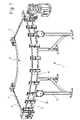
- a Kurvengurt unit 1 is shown in a perspective view.
- This has, on the one hand, a frame 2 on which a conveyor belt 3 revolves, with a difference being made in the conveyor belt between the upper side 4 and the lower side 5.
- deflection rollers 6 are provided, around which the conveyor belt rotates.
- Rollers 20 are provided on a side wall profile 7, which engage a engaging element 8 arranged on the outer edge of the conveyor belt 3 and in this way guide the conveyor belt 3.
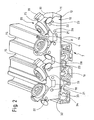
- Fig. 2 is a perspective view of a portion of the side wall profile 7 is shown with a holding member 10 which is fixed to the side wall profile, and on which four rollers 20 are mounted.
- the holding element 10 is designed in the manner of a U-profile and has a bottom 11 or bottom portion, from which extend at right angles two legs 12 and 13 parallel to each other.
- a number of recesses 14 are provided through which a connection of the holding member 10 with the side wall profile 7 takes place.
- a plurality of grooves 15 are provided, in which clamping blocks 16 can be arranged, which are bolted to the holding element 10 through the recesses 14 and fixed.
- the holding element 10 is aligned vertically overall, so that the four rollers 20 are arranged one above the other. Between each pair of rollers which form a pair of rollers, a conveyor belt, in particular an engagement element 8 of the conveyor belt is guided. In the drawing, the engagement element 8 is shown with arms 9 formed therewith. Between these arms 9, the conveyor belt 3 is inserted and connected to the arms, for example by gluing and / or a seam connection.
- the rollers 20 of a pair of rollers are under a wink! between 100 ° and 120 °, in particular 110 ° to each other and thus act on both sides of the engagement element 8 of the conveyor belt 3, the Indian Fig. 2 not shown.
- the rollers 20 are mounted on roller holders 25, which in turn are received in the holding element 10.
- the holding elements 25 are arranged on the opposite legs 12, 13 of the holding element 10, in particular on the inner sides of the legs 12, 13 attached.
- at least one roller 20 is pivotally mounted.
- a plurality of recesses 21, 22, 23 are provided in the legs 12, 13.
- a latching recess 21 is arranged on the conveyor belt side facing the roller 20 and two locking recesses 22 and 23 are arranged at some distance from each other on the side remote from the conveyor belt side of the legs of the U-profile.
- the roller holder 25 has two latching noses 26 and 27, which correspond to the recesses and form with these attachment points.
- the locking lug 26 is firmly locked in the latching recess 21, wherein the roller holder 25 is pivotable about an axis extending through the latching lug 25 axis.
- the latching lug 27 can be moved either into the latching recess 22 or the latching recess 23. In the illustrated in the figure locking the locking lug 27 in the recess 22 of the conveyor belt or the engaging element 8 of the conveyor belt is taken from the rollers 20 into engagement. If the roller holder 25 is moved downwards, so that the latching nose 22 clicks into the latching recess 23, the entire roller 20 is pivoted downwards and the conveyor belt is released and can then be removed for maintenance purposes.
- the change in position takes place on both sides of the roller holder 25 provided actuating lever 29, which can be pressed by an operator inwardly, so that then the locking lug 27 is pushed out of the recess 22 inwardly, can be moved and then upon release of the actuating lever 29th in the desired other position, ie in particular the locking recesses 23 engages again.
- the holding element 10, in particular the legs 12 and 13 of the U-profile have between the paired rollers 20 recesses 18, so that in this the conveyor belt can run.
- the upper portions 19 of the legs 12 and 13 are made at an angle of about 55 ° and inclined towards each other. This upper portion 19 is thus parallel to the arranged in the engagement position rollers 20.
- two pairs of rollers are arranged on the one-piece support member 10.
- two recesses 18 are provided in the legs, which are each arranged between two rollers of a pair of rollers.
- a second recess 28 is arranged between the two roller pairs and serves to allow the roller holders 25 and in particular the actuating levers 29, which protrude beyond the retaining element 10, to be moved downwards.
- Attention is also drawn to an asymmetry resulting from the orientation of the retaining element 10, namely the recess 32 located in the lower end region, by means of which an edge 33 is formed in the region of the bottom 11 of the retaining element 10 which abuts against a projecting shoulder 34 of the side wall profile 7 strikes. The end region is directed downwards, so that the force acting on the holding element 10 can be mechanically supported even better on the side wall profile 7.
- Fig. 3 is a detailed perspective view of the holding member 10 is shown, wherein the right in the Fig. Right roller 20 between the legs 12 and 13 of the U-shaped profile is pivoted. Thereby, the conveyor belt or arranged on the conveyor belt attack element 8 is released and the belt can be removed.
- the locking lug 27 of the roller holder 25 is no longer locked in the latching recess 22, but in the recess 23.
- the roller holder 25 is thus given down and thus also the roller 20 which rotates on the axis 35 of the roller holder 25, swung.
- the distances between the legs 12 and 13 to each other are such that the roller 20 can be swung in between them.
- Fig. 4 a perspective view of a roller holder 25 is shown.
- the axis 35 arranged on the roller holder and the lateral latching noses 26 and 27 and the actuating lever 29 have already been described.
- the axis 35 is arranged on a central and very stable central block 36 which is connected to the two outer side elements 39 via transverse struts 37.
- On the side members 39 which are dimensioned so that they are tightly fitted on the inside between the legs 12 and 13 of the support member, the locking lugs 26 and 27 are formed.
- the side members 39 are in the front region, ie in particular between the belt facing locking lug 26 to the cross brace 37 rigid.
- the side elements 39 In the rear area, that is to say in particular between the transverse strut 37 and the rear latching lug 27, the side elements 39 have a material weakening 40, so that bending of the side elements 39 takes place in a defined manner in this area due to pressure on the actuating lever 39, so that the latching lug 27 protrudes the respective latching recess 22 or 23 can be moved.
Landscapes
- Engineering & Computer Science (AREA)
- Mechanical Engineering (AREA)
- Structure Of Belt Conveyors (AREA)
- Rehabilitation Tools (AREA)
- Rollers For Roller Conveyors For Transfer (AREA)
Claims (14)
- Convoyeur à bande courbée comprenant une bande de convoyage (3) qui présente un élément d'attaque (8) au niveau de l'arête formant le bord extérieur, qui est dirigé par plusieurs rouleaux (20) disposés par paires, sachant que chaque paire de rouleaux (20) est disposée sur un élément de retenue (10),
caractérisé en ce que
l'élément de retenue (10) est formé en tant que profilé en U avec un fond (11) et deux branches (12, 13), et
que les rouleaux (20) sont fixés sur les branches (12, 13) opposées du profilé en U par des fixations de rouleau (25) correspondantes. - Convoyeur à bande courbée selon la revendication 1, caractérisé en ce que la fixation de rouleau (25) est fixée sur les côtés intérieurs des branches (12, 13) opposées du profilé en U.
- Convoyeur à bande courbée selon la revendication 1 ou 2, caractérisé en ce que l'axe de rotation (35) d'au moins un rouleau peut pivoter dans un plan parallèle entre les branches (12, 13) du profilé en U.
- Convoyeur à bande courbée selon l'une des revendications précédentes, caractérisé en ce qu'au moins une fixation de rouleau (25) a deux points de fixation avec chaque branche (12, 13) du profilé en U, sachant que le point de fixation (21, 26) tourné vers la bande de convoyage (7), permet une rotation de la fixation de rouleau (25) sur ce point de fixation (21, 26) et en ce que le point de fixation (22, 23, 27) détourné de la bande de convoyage (7) est modifiable entre deux positions de telle sorte, que dans une position, le rouleau (20) repose sur la bande de convoyage (7) et dans une autre position, le rouleau libère la bande de convoyage.
- Convoyeur à bande courbée selon l'une des revendications précédentes, caractérisé en ce que l'écart entre les branches (12, 13) du profilé en U est supérieur au diamètre du rouleau (20).
- Convoyeur à bande courbée selon l'une des revendications précédentes, caractérisé en ce que la fixation de rouleau (25) présente un levier d'actionnement (29) qui peut être déformé mécaniquement, de sorte qu'un point de fixation (22, 23, 27) de la fixation de rouleau (25) est séparable de façon réversible.
- Convoyeur à bande courbée selon la revendication 6, caractérisé en ce qu'un point de fixation est formé par des éléments d'encliquetage correspondants sur le levier d'actionnement de la fixation de rouleau et la branche du profilé en U.
- Convoyeur à bande courbée selon la revendication 6 ou 7, caractérisé en ce que le levier d'actionnement (28) présente un ergot d'encliquetage (27), qui peut être fixé de façon réversible à l'intérieur de l'un de plusieurs évidements d'encliquetage (22, 23) dans les branches (12, 13) du profilé en U.
- Convoyeur à bande courbée selon l'une des revendications 4 à 8, caractérisé en ce que la fixation de rouleau (25) est rigide au niveau du point de fixation tourné vers la bande de convoyage (7) et de la réception du rouleau, et que la fixation de rouleau est moins rigide au niveau du point de fixation détourné de la bande de convoyage.
- Convoyeur à bande courbée selon la revendication 9, caractérisé en ce que la fixation de rouleau présente des éléments latéraux (39) qui présentent un affaiblissement de matériau (40) dans la transition vers le levier d'actionnement (29).
- Convoyeur à bande courbée selon l'une des revendications précédentes, caractérisé en ce que les branches (12, 13) du profilé en U présentent un évidement (18) entre deux rouleaux (20) formant une paire de rouleaux.
- Convoyeur à bande courbée selon l'une des revendications précédentes, caractérisé en ce que quatre rouleaux sont disposés sur un profilé en U monobloc, sachant que deux rouleaux forment une paire de rouleaux pour le côté du brin supérieur de la bande de convoyage et deux rouleaux forment une paire de rouleaux pour le côté du brin inférieur de la bande de convoyage.
- Convoyeur à bande courbée selon la revendication 12, caractérisé en ce que les branches (12, 13) du profilé en U présentent un évidement (28) dans la partie entre les paires de rouleaux.
- Élément de retenue pour un convoyeur à bande courbée sur lequel au moins deux rouleaux agencés en paire sont disposés,
caractérisé en ce que
l'élément de retenue est formé en tant que profilé en U avec un fond et deux branches, et
que les rouleaux (20) sont fixés sur les branches (12, 13) opposées du profilé en U par des fixations de rouleau (25) correspondantes.
Applications Claiming Priority (1)
| Application Number | Priority Date | Filing Date | Title |
|---|---|---|---|
| PCT/DE2011/000410 WO2012139538A1 (fr) | 2011-04-14 | 2011-04-14 | Transporteur courbe à bande et élément de retenue à rouleaux pour un transporteur courbe à bande |
Publications (2)
| Publication Number | Publication Date |
|---|---|
| EP2697140A1 EP2697140A1 (fr) | 2014-02-19 |
| EP2697140B1 true EP2697140B1 (fr) | 2014-09-17 |
Family
ID=44627066
Family Applications (1)
| Application Number | Title | Priority Date | Filing Date |
|---|---|---|---|
| EP11725312.0A Active EP2697140B1 (fr) | 2011-04-14 | 2011-04-14 | Convoyeur a bande courbee et element de retenue a rouleaux pour ledit convoyeur |
Country Status (10)
| Country | Link |
|---|---|
| US (1) | US9120628B2 (fr) |
| EP (1) | EP2697140B1 (fr) |
| JP (1) | JP5714174B2 (fr) |
| KR (1) | KR101660098B1 (fr) |
| CN (1) | CN103582602B (fr) |
| BR (1) | BR112013026204B1 (fr) |
| CA (1) | CA2832351A1 (fr) |
| DK (1) | DK2697140T3 (fr) |
| ES (1) | ES2526146T3 (fr) |
| WO (1) | WO2012139538A1 (fr) |
Cited By (2)
| Publication number | Priority date | Publication date | Assignee | Title |
|---|---|---|---|---|
| JP2014510685A (ja) * | 2011-04-14 | 2014-05-01 | トランスノーム システム ゲゼルシャフト ミット ベシュレンクテル ハフツング | カーブベルトコンベヤ及びカーブベルトコンベヤ用のローラを備えた保持エレメント |
| US20140367228A1 (en) * | 2013-06-14 | 2014-12-18 | James Laverdiere | Conveyor assembly and associated method |
Families Citing this family (12)
| Publication number | Priority date | Publication date | Assignee | Title |
|---|---|---|---|---|
| NL2009721C2 (nl) * | 2012-10-29 | 2014-05-01 | Rexnord Flattop Europe Bv | Eindaandrijving voor een transporteur, transporteur voorzien van een eindaandrijving, en aandrijftandwiel voor een eindaandrijving. |
| FR3017379B1 (fr) * | 2014-02-13 | 2017-11-24 | Ceric | Table pour convoyeur a bande, procede de montage et procede de demontage d'un convoyeur a bande comprenant la table |
| US9776795B2 (en) * | 2014-08-15 | 2017-10-03 | Sanki Engineering Co., Ltd. | Curved belt conveyor apparatus |
| KR102208735B1 (ko) | 2015-07-09 | 2021-01-28 | 삼성전자 주식회사 | 금속 하우징을 가지는 전자 장치 및 그 제조 방법 |
| MY201220A (en) | 2018-06-12 | 2024-02-09 | Kairos Conveyor Sdn Bhd | A rapid release mechanism for a curved belt conveyor and a method of using the rapid release mechanism thereof |
| CN109775237B (zh) * | 2019-01-21 | 2021-03-26 | 金锋馥(滁州)输送机械有限公司 | 一种环形输送带 |
| EP3715286B1 (fr) * | 2019-03-28 | 2021-10-06 | BEUMER Group GmbH & Co. KG | Protection ajustable contre le coincement d'une bande transporteuse |
| CN114043263B (zh) * | 2021-11-08 | 2023-11-21 | 陕西飞机工业有限责任公司 | 一种曲度带弯边零件弯边边缘精度铣切导轨夹具 |
| MY210393A (en) | 2022-02-15 | 2025-09-18 | Kairos Global Sdn Bhd | Rapid release belt guidance mechanism |
| IT202200003830A1 (it) | 2022-03-01 | 2023-09-01 | Mech Sistemi S R L | Curved belt conveyor |
| DE102023102117A1 (de) | 2023-01-30 | 2024-08-01 | Schmid Systemtechnik GmbH | Gurtniederhalter und Gurtförderer |
| EP4669601A1 (fr) | 2023-02-20 | 2025-12-31 | Kairos Global Sdn. Bhd. | Ensemble structural de fixation mécanique et procédé d'utilisation pour transporteurs à courroie incurvée |
Family Cites Families (19)
| Publication number | Priority date | Publication date | Assignee | Title |
|---|---|---|---|---|
| JPS5444942Y2 (fr) * | 1977-08-18 | 1979-12-24 | ||
| JPS61163210U (fr) * | 1985-03-29 | 1986-10-09 | ||
| DE3826953A1 (de) * | 1988-08-09 | 1990-03-01 | Transnorm System Gmbh | Kurvengurtfoerderer |
| DE9300876U1 (de) * | 1993-01-25 | 1993-05-06 | Transnorm-System-GmbH, 3207 Harsum | Kurvengurtförderer |
| DK170746B1 (da) | 1993-05-26 | 1996-01-08 | Seelen As | Kurveformet bæltetransportør |
| US5394977A (en) * | 1993-07-08 | 1995-03-07 | Portec, Inc. | Apparatus and method for use in replacing conveyor belts |
| GB9321728D0 (en) * | 1993-10-21 | 1993-12-15 | Gramac Mechanical Handling Lim | Improvements relating to conveyors |
| NL9402081A (nl) * | 1994-12-09 | 1996-07-01 | Vanderlande Ind Nederland | Transportinrichting. |
| DE29502064U1 (de) * | 1995-02-10 | 1995-06-01 | Transnorm-System-GmbH, 31177 Harsum | Kurvengurtförderer |
| NL1004699C2 (nl) | 1996-12-05 | 1998-06-08 | Vanderlande Ind Nederland | Transportinrichting. |
| JP4445076B2 (ja) * | 1999-10-26 | 2010-04-07 | バンドー化学株式会社 | 湾曲走行ベルトコンベヤ |
| JP3430143B2 (ja) * | 2000-10-11 | 2003-07-28 | ハバジット日本株式会社 | カーブベルトの支持装置 |
| US7232030B2 (en) * | 2004-11-24 | 2007-06-19 | Transnorm System Inc. | Quick release holder for a beading of a conveyor belt and method of using quick release holder |
| JP4708805B2 (ja) | 2005-02-04 | 2011-06-22 | 三機工業株式会社 | ベルトカーブコンベヤ |
| WO2006084407A1 (fr) * | 2005-02-10 | 2006-08-17 | Robert Bosch Gmbh | Convoyeur à courroie curviligne |
| DE102006024536C5 (de) * | 2006-05-23 | 2012-10-18 | Logcomp Gmbh | Kurvengurtförderer |
| CN201086992Y (zh) * | 2007-03-22 | 2008-07-16 | 新田株式会社 | 皮带保持装置 |
| EP2275365A1 (fr) | 2009-07-17 | 2011-01-19 | Cecilia Vila Torra | Système de guidage et de support pour courroies incurvées de convoyeur |
| EP2697140B1 (fr) * | 2011-04-14 | 2014-09-17 | TRANSNORM SYSTEM GmbH | Convoyeur a bande courbee et element de retenue a rouleaux pour ledit convoyeur |
-
2011
- 2011-04-14 EP EP11725312.0A patent/EP2697140B1/fr active Active
- 2011-04-14 ES ES11725312.0T patent/ES2526146T3/es active Active
- 2011-04-14 DK DK11725312.0T patent/DK2697140T3/en active
- 2011-04-14 CA CA2832351A patent/CA2832351A1/fr not_active Abandoned
- 2011-04-14 KR KR1020137026722A patent/KR101660098B1/ko active Active
- 2011-04-14 WO PCT/DE2011/000410 patent/WO2012139538A1/fr not_active Ceased
- 2011-04-14 CN CN201180070122.2A patent/CN103582602B/zh active Active
- 2011-04-14 JP JP2014504154A patent/JP5714174B2/ja active Active
- 2011-04-14 US US14/110,771 patent/US9120628B2/en active Active
- 2011-04-14 BR BR112013026204-4A patent/BR112013026204B1/pt active IP Right Grant
Cited By (3)
| Publication number | Priority date | Publication date | Assignee | Title |
|---|---|---|---|---|
| JP2014510685A (ja) * | 2011-04-14 | 2014-05-01 | トランスノーム システム ゲゼルシャフト ミット ベシュレンクテル ハフツング | カーブベルトコンベヤ及びカーブベルトコンベヤ用のローラを備えた保持エレメント |
| US20140367228A1 (en) * | 2013-06-14 | 2014-12-18 | James Laverdiere | Conveyor assembly and associated method |
| US9227784B2 (en) * | 2013-06-14 | 2016-01-05 | Kleenline Llc | Conveyor assembly and associated method |
Also Published As
| Publication number | Publication date |
|---|---|
| KR20140010140A (ko) | 2014-01-23 |
| CN103582602A (zh) | 2014-02-12 |
| US9120628B2 (en) | 2015-09-01 |
| ES2526146T3 (es) | 2015-01-07 |
| EP2697140A1 (fr) | 2014-02-19 |
| HK1191625A1 (zh) | 2014-08-01 |
| JP2014510685A (ja) | 2014-05-01 |
| KR101660098B1 (ko) | 2016-09-26 |
| BR112013026204A2 (pt) | 2019-09-17 |
| CN103582602B (zh) | 2015-12-16 |
| WO2012139538A1 (fr) | 2012-10-18 |
| BR112013026204B1 (pt) | 2020-09-29 |
| JP5714174B2 (ja) | 2015-05-07 |
| US20140027248A1 (en) | 2014-01-30 |
| DK2697140T3 (en) | 2015-01-05 |
| CA2832351A1 (fr) | 2012-10-18 |
Similar Documents
| Publication | Publication Date | Title |
|---|---|---|
| WO2012139538A1 (fr) | Transporteur courbe à bande et élément de retenue à rouleaux pour un transporteur courbe à bande | |
| EP3718185B1 (fr) | Pince à dénuder | |
| DE19729444B4 (de) | Stapelsäule zum Lagern von Lagergütern | |
| DE29914501U1 (de) | Innenrückblickspiegel für Fahrzeuge | |
| EP3016551B1 (fr) | Élément de tablette pour une tablette d'une étagère, en particulier d'une étagère à glissière, ainsi que cadre de tablette, tablette et étagère | |
| EP3491966B1 (fr) | Dispositif de raccordement et meuble ou appareil électroménager | |
| WO2019105702A2 (fr) | Mâchoires de serrage et bords tranchants pour pince à dénuder ainsi que pince à dénuder | |
| DE202006004641U1 (de) | Greifelement | |
| EP3403738A1 (fr) | Plieuse de tôles | |
| EP3448739A1 (fr) | Appareil de transport pouvant être déplacé manuellement | |
| DE202016101921U1 (de) | Haltevorrichtung für ein Zweirad und Zweiradparkanlage | |
| EP1802835A1 (fr) | Liaison par serrage entre le sabot de serrage d'un chariot et un volet coulissant | |
| DE102014102626B4 (de) | Kettenglied für eine Energieführungskette | |
| DE102016101466B4 (de) | Fahrradbremse | |
| WO2019007798A1 (fr) | Dispositif pour guider des contenants pour un convoyeur | |
| DE19931953A1 (de) | Beschlag zur Lagerung eines Endes einer Latte eines Lattenrahmens | |
| DE2218832A1 (de) | Hebeklemme | |
| EP3359478B1 (fr) | Courroie de pliage pour dispositif de pliage de découpes à plat de boîte pliante | |
| EP3737262B1 (fr) | Dispositif constitué par une glissière télescopique et un entraîneur | |
| DE4225833C2 (de) | Biegevorrichtung für Hohlprofile | |
| EP3894326B1 (fr) | Support de tube pour une machine de remplissage de tubes | |
| DE202015104529U1 (de) | Pflanzenkastenhalter | |
| DE102007039848A1 (de) | Schwenkbiegemaschine | |
| EP2840049B1 (fr) | Dispositif de transport d'un prospectus | |
| EP2431616B1 (fr) | Etrier de serrage |
Legal Events
| Date | Code | Title | Description |
|---|---|---|---|
| PUAI | Public reference made under article 153(3) epc to a published international application that has entered the european phase |
Free format text: ORIGINAL CODE: 0009012 |
|
| 17P | Request for examination filed |
Effective date: 20130928 |
|
| AK | Designated contracting states |
Kind code of ref document: A1 Designated state(s): AL AT BE BG CH CY CZ DE DK EE ES FI FR GB GR HR HU IE IS IT LI LT LU LV MC MK MT NL NO PL PT RO RS SE SI SK SM TR |
|
| GRAP | Despatch of communication of intention to grant a patent |
Free format text: ORIGINAL CODE: EPIDOSNIGR1 |
|
| DAX | Request for extension of the european patent (deleted) | ||
| INTG | Intention to grant announced |
Effective date: 20140522 |
|
| GRAS | Grant fee paid |
Free format text: ORIGINAL CODE: EPIDOSNIGR3 |
|
| GRAA | (expected) grant |
Free format text: ORIGINAL CODE: 0009210 |
|
| AK | Designated contracting states |
Kind code of ref document: B1 Designated state(s): AL AT BE BG CH CY CZ DE DK EE ES FI FR GB GR HR HU IE IS IT LI LT LU LV MC MK MT NL NO PL PT RO RS SE SI SK SM TR |
|
| REG | Reference to a national code |
Ref country code: GB Ref legal event code: FG4D Free format text: NOT ENGLISH |
|
| REG | Reference to a national code |
Ref country code: CH Ref legal event code: EP |
|
| REG | Reference to a national code |
Ref country code: IE Ref legal event code: FG4D Free format text: LANGUAGE OF EP DOCUMENT: GERMAN |
|
| REG | Reference to a national code |
Ref country code: CH Ref legal event code: NV Representative=s name: PATENTANWAELTE SCHAAD, BALASS, MENZL AND PARTN, CH Ref country code: AT Ref legal event code: REF Ref document number: 687588 Country of ref document: AT Kind code of ref document: T Effective date: 20141015 |
|
| REG | Reference to a national code |
Ref country code: DE Ref legal event code: R096 Ref document number: 502011004411 Country of ref document: DE Effective date: 20141030 |
|
| REG | Reference to a national code |
Ref country code: NL Ref legal event code: T3 |
|
| REG | Reference to a national code |
Ref country code: DK Ref legal event code: T3 Effective date: 20141218 |
|
| REG | Reference to a national code |
Ref country code: ES Ref legal event code: FG2A Ref document number: 2526146 Country of ref document: ES Kind code of ref document: T3 Effective date: 20150107 |
|
| PG25 | Lapsed in a contracting state [announced via postgrant information from national office to epo] |
Ref country code: NO Free format text: LAPSE BECAUSE OF FAILURE TO SUBMIT A TRANSLATION OF THE DESCRIPTION OR TO PAY THE FEE WITHIN THE PRESCRIBED TIME-LIMIT Effective date: 20141217 Ref country code: SE Free format text: LAPSE BECAUSE OF FAILURE TO SUBMIT A TRANSLATION OF THE DESCRIPTION OR TO PAY THE FEE WITHIN THE PRESCRIBED TIME-LIMIT Effective date: 20140917 Ref country code: LT Free format text: LAPSE BECAUSE OF FAILURE TO SUBMIT A TRANSLATION OF THE DESCRIPTION OR TO PAY THE FEE WITHIN THE PRESCRIBED TIME-LIMIT Effective date: 20140917 Ref country code: FI Free format text: LAPSE BECAUSE OF FAILURE TO SUBMIT A TRANSLATION OF THE DESCRIPTION OR TO PAY THE FEE WITHIN THE PRESCRIBED TIME-LIMIT Effective date: 20140917 Ref country code: GR Free format text: LAPSE BECAUSE OF FAILURE TO SUBMIT A TRANSLATION OF THE DESCRIPTION OR TO PAY THE FEE WITHIN THE PRESCRIBED TIME-LIMIT Effective date: 20141218 |
|
| REG | Reference to a national code |
Ref country code: LT Ref legal event code: MG4D |
|
| PG25 | Lapsed in a contracting state [announced via postgrant information from national office to epo] |
Ref country code: HR Free format text: LAPSE BECAUSE OF FAILURE TO SUBMIT A TRANSLATION OF THE DESCRIPTION OR TO PAY THE FEE WITHIN THE PRESCRIBED TIME-LIMIT Effective date: 20140917 Ref country code: RS Free format text: LAPSE BECAUSE OF FAILURE TO SUBMIT A TRANSLATION OF THE DESCRIPTION OR TO PAY THE FEE WITHIN THE PRESCRIBED TIME-LIMIT Effective date: 20140917 Ref country code: LV Free format text: LAPSE BECAUSE OF FAILURE TO SUBMIT A TRANSLATION OF THE DESCRIPTION OR TO PAY THE FEE WITHIN THE PRESCRIBED TIME-LIMIT Effective date: 20140917 Ref country code: CY Free format text: LAPSE BECAUSE OF FAILURE TO SUBMIT A TRANSLATION OF THE DESCRIPTION OR TO PAY THE FEE WITHIN THE PRESCRIBED TIME-LIMIT Effective date: 20140917 |
|
| PG25 | Lapsed in a contracting state [announced via postgrant information from national office to epo] |
Ref country code: SK Free format text: LAPSE BECAUSE OF FAILURE TO SUBMIT A TRANSLATION OF THE DESCRIPTION OR TO PAY THE FEE WITHIN THE PRESCRIBED TIME-LIMIT Effective date: 20140917 Ref country code: IS Free format text: LAPSE BECAUSE OF FAILURE TO SUBMIT A TRANSLATION OF THE DESCRIPTION OR TO PAY THE FEE WITHIN THE PRESCRIBED TIME-LIMIT Effective date: 20150117 Ref country code: EE Free format text: LAPSE BECAUSE OF FAILURE TO SUBMIT A TRANSLATION OF THE DESCRIPTION OR TO PAY THE FEE WITHIN THE PRESCRIBED TIME-LIMIT Effective date: 20140917 Ref country code: PT Free format text: LAPSE BECAUSE OF FAILURE TO SUBMIT A TRANSLATION OF THE DESCRIPTION OR TO PAY THE FEE WITHIN THE PRESCRIBED TIME-LIMIT Effective date: 20150119 Ref country code: RO Free format text: LAPSE BECAUSE OF FAILURE TO SUBMIT A TRANSLATION OF THE DESCRIPTION OR TO PAY THE FEE WITHIN THE PRESCRIBED TIME-LIMIT Effective date: 20140917 Ref country code: CZ Free format text: LAPSE BECAUSE OF FAILURE TO SUBMIT A TRANSLATION OF THE DESCRIPTION OR TO PAY THE FEE WITHIN THE PRESCRIBED TIME-LIMIT Effective date: 20140917 |
|
| PG25 | Lapsed in a contracting state [announced via postgrant information from national office to epo] |
Ref country code: PL Free format text: LAPSE BECAUSE OF FAILURE TO SUBMIT A TRANSLATION OF THE DESCRIPTION OR TO PAY THE FEE WITHIN THE PRESCRIBED TIME-LIMIT Effective date: 20140917 |
|
| REG | Reference to a national code |
Ref country code: DE Ref legal event code: R097 Ref document number: 502011004411 Country of ref document: DE |
|
| PLBE | No opposition filed within time limit |
Free format text: ORIGINAL CODE: 0009261 |
|
| STAA | Information on the status of an ep patent application or granted ep patent |
Free format text: STATUS: NO OPPOSITION FILED WITHIN TIME LIMIT |
|
| 26N | No opposition filed |
Effective date: 20150618 |
|
| PG25 | Lapsed in a contracting state [announced via postgrant information from national office to epo] |
Ref country code: SI Free format text: LAPSE BECAUSE OF FAILURE TO SUBMIT A TRANSLATION OF THE DESCRIPTION OR TO PAY THE FEE WITHIN THE PRESCRIBED TIME-LIMIT Effective date: 20140917 Ref country code: MC Free format text: LAPSE BECAUSE OF FAILURE TO SUBMIT A TRANSLATION OF THE DESCRIPTION OR TO PAY THE FEE WITHIN THE PRESCRIBED TIME-LIMIT Effective date: 20140917 |
|
| REG | Reference to a national code |
Ref country code: IE Ref legal event code: MM4A |
|
| REG | Reference to a national code |
Ref country code: FR Ref legal event code: PLFP Year of fee payment: 6 |
|
| PG25 | Lapsed in a contracting state [announced via postgrant information from national office to epo] |
Ref country code: IE Free format text: LAPSE BECAUSE OF NON-PAYMENT OF DUE FEES Effective date: 20150414 |
|
| PG25 | Lapsed in a contracting state [announced via postgrant information from national office to epo] |
Ref country code: MT Free format text: LAPSE BECAUSE OF FAILURE TO SUBMIT A TRANSLATION OF THE DESCRIPTION OR TO PAY THE FEE WITHIN THE PRESCRIBED TIME-LIMIT Effective date: 20140917 |
|
| REG | Reference to a national code |
Ref country code: FR Ref legal event code: PLFP Year of fee payment: 7 |
|
| PG25 | Lapsed in a contracting state [announced via postgrant information from national office to epo] |
Ref country code: HU Free format text: LAPSE BECAUSE OF FAILURE TO SUBMIT A TRANSLATION OF THE DESCRIPTION OR TO PAY THE FEE WITHIN THE PRESCRIBED TIME-LIMIT; INVALID AB INITIO Effective date: 20110414 Ref country code: SM Free format text: LAPSE BECAUSE OF FAILURE TO SUBMIT A TRANSLATION OF THE DESCRIPTION OR TO PAY THE FEE WITHIN THE PRESCRIBED TIME-LIMIT Effective date: 20140917 Ref country code: BG Free format text: LAPSE BECAUSE OF FAILURE TO SUBMIT A TRANSLATION OF THE DESCRIPTION OR TO PAY THE FEE WITHIN THE PRESCRIBED TIME-LIMIT Effective date: 20140917 |
|
| PG25 | Lapsed in a contracting state [announced via postgrant information from national office to epo] |
Ref country code: BE Free format text: LAPSE BECAUSE OF NON-PAYMENT OF DUE FEES Effective date: 20150430 |
|
| REG | Reference to a national code |
Ref country code: FR Ref legal event code: PLFP Year of fee payment: 8 |
|
| PG25 | Lapsed in a contracting state [announced via postgrant information from national office to epo] |
Ref country code: MK Free format text: LAPSE BECAUSE OF FAILURE TO SUBMIT A TRANSLATION OF THE DESCRIPTION OR TO PAY THE FEE WITHIN THE PRESCRIBED TIME-LIMIT Effective date: 20140917 |
|
| PG25 | Lapsed in a contracting state [announced via postgrant information from national office to epo] |
Ref country code: AL Free format text: LAPSE BECAUSE OF FAILURE TO SUBMIT A TRANSLATION OF THE DESCRIPTION OR TO PAY THE FEE WITHIN THE PRESCRIBED TIME-LIMIT Effective date: 20140917 |
|
| REG | Reference to a national code |
Ref country code: DE Ref legal event code: R082 Ref document number: 502011004411 Country of ref document: DE |
|
| PGFP | Annual fee paid to national office [announced via postgrant information from national office to epo] |
Ref country code: NL Payment date: 20250424 Year of fee payment: 15 |
|
| PGFP | Annual fee paid to national office [announced via postgrant information from national office to epo] |
Ref country code: LU Payment date: 20250424 Year of fee payment: 15 |
|
| PGFP | Annual fee paid to national office [announced via postgrant information from national office to epo] |
Ref country code: DE Payment date: 20250428 Year of fee payment: 15 |
|
| PGFP | Annual fee paid to national office [announced via postgrant information from national office to epo] |
Ref country code: GB Payment date: 20250422 Year of fee payment: 15 Ref country code: ES Payment date: 20250513 Year of fee payment: 15 Ref country code: DK Payment date: 20250424 Year of fee payment: 15 |
|
| PGFP | Annual fee paid to national office [announced via postgrant information from national office to epo] |
Ref country code: IT Payment date: 20250422 Year of fee payment: 15 |
|
| PGFP | Annual fee paid to national office [announced via postgrant information from national office to epo] |
Ref country code: FR Payment date: 20250424 Year of fee payment: 15 |
|
| PGFP | Annual fee paid to national office [announced via postgrant information from national office to epo] |
Ref country code: CH Payment date: 20250501 Year of fee payment: 15 |
|
| PGFP | Annual fee paid to national office [announced via postgrant information from national office to epo] |
Ref country code: AT Payment date: 20250417 Year of fee payment: 15 |
|
| PGFP | Annual fee paid to national office [announced via postgrant information from national office to epo] |
Ref country code: TR Payment date: 20250403 Year of fee payment: 15 |
|
| REG | Reference to a national code |
Ref country code: CH Ref legal event code: U11 Free format text: ST27 STATUS EVENT CODE: U-0-0-U10-U11 (AS PROVIDED BY THE NATIONAL OFFICE) Effective date: 20260501 |