EP2698280A1 - Faltspiegel mit Doppelarretierung - Google Patents
Faltspiegel mit Doppelarretierung Download PDFInfo
- Publication number
- EP2698280A1 EP2698280A1 EP12382326.2A EP12382326A EP2698280A1 EP 2698280 A1 EP2698280 A1 EP 2698280A1 EP 12382326 A EP12382326 A EP 12382326A EP 2698280 A1 EP2698280 A1 EP 2698280A1
- Authority
- EP
- European Patent Office
- Prior art keywords
- ring
- wedged
- pivot
- mirror
- abutment
- Prior art date
- Legal status (The legal status is an assumption and is not a legal conclusion. Google has not performed a legal analysis and makes no representation as to the accuracy of the status listed.)
- Granted
Links
Images








Classifications
-
- B—PERFORMING OPERATIONS; TRANSPORTING
- B60—VEHICLES IN GENERAL
- B60R—VEHICLES, VEHICLE FITTINGS, OR VEHICLE PARTS, NOT OTHERWISE PROVIDED FOR
- B60R1/00—Optical viewing arrangements; Real-time viewing arrangements for drivers or passengers using optical image capturing systems, e.g. cameras or video systems specially adapted for use in or on vehicles
- B60R1/02—Rear-view mirror arrangements
- B60R1/06—Rear-view mirror arrangements mounted on vehicle exterior
- B60R1/062—Rear-view mirror arrangements mounted on vehicle exterior with remote control for adjusting position
- B60R1/07—Rear-view mirror arrangements mounted on vehicle exterior with remote control for adjusting position by electrically powered actuators
- B60R1/074—Rear-view mirror arrangements mounted on vehicle exterior with remote control for adjusting position by electrically powered actuators for retracting the mirror arrangements to a non-use position alongside the vehicle
-
- B—PERFORMING OPERATIONS; TRANSPORTING
- B60—VEHICLES IN GENERAL
- B60R—VEHICLES, VEHICLE FITTINGS, OR VEHICLE PARTS, NOT OTHERWISE PROVIDED FOR
- B60R1/00—Optical viewing arrangements; Real-time viewing arrangements for drivers or passengers using optical image capturing systems, e.g. cameras or video systems specially adapted for use in or on vehicles
- B60R1/02—Rear-view mirror arrangements
- B60R1/06—Rear-view mirror arrangements mounted on vehicle exterior
- B60R1/076—Rear-view mirror arrangements mounted on vehicle exterior yieldable to excessive external force and provided with an indexed use position
Definitions
- the present invention relates to a powered folding mirror, in particular suitable for vehicles, that has two lock positions: a folded position and an unfolded position locked according to the driving position.
- present invention allows to manually unfold it in such a way the mirror is locked in the same driving angular position as it was locked when unfolded by means of the electrical motor.
- Present invention overcomes the drawbacks of the prior art providing a double detent wherein the folding mirror, when unfolded manually from the parking position reached by means of the electrical motor, to the driving position, has a detent in the driving position; the same angular position reached by the electrical motor.
- the present invention relates to a double detent folding mirror providing a first detent in the driving angular position of the mirror when unfolded by means of the electrical motor and a second detent in the same driving angular position of the mirror when unfolded manually.
- the powered mirror is disclosed as powered by means of an electrical motor but this feature is not essential and it has to be interpreted that any motor, for instance pneumatic one, can be used versus manual action.
- the powered mirror according to a first aspect of the invention comprises:
- This base is the nonmoving reference of the system and is fixed to the vehicle.
- This base has a pivot oriented essentially upright which defines the axis of the rotational movement of the mirror. The other pieces are referenced with respect to this axis and this base.
- the mirror has two lock positions which means that the mirror is retained in such position unless a certain force (a torque) reaches a threshold value. For instance, if the mirror is folded because it has been moved by means of the motor, then it can be unfolded manually applying a force greater than the detent force.
- This pivot has axial guiding means used by some pieces of the device according to the invention in order to limit the movement of such pieces to an axial movement.
- This spring is an elastic mean adapted to exert an axial force to the pieces it rests on.
- the upper part is axially fixed and the lower part is exerting the axial force.
- the first ring is a ring with axial movement and pressed downwardly by means of the spring. This first ring is axially guided and it is not rotatable around the pivot because the motor impulses the mirror acting over the fixed base throughout this first ring.
- the internal annular sector is related to the interaction of the motor by means of a further piece with a flange that will be characterized below, that is, the internal annular sector is related to the powered movement.
- the interaction with the motor and the first detent of the mirror is obtained thanks to the centered housing resulting from the two double-wedged projections separated by such housing and the flange as it will be disclosed in the extended description of the invention.
- the external annular sector is related to the interaction of the rotatable frame when moved manually, by means of a further ring that will also be characterized below.
- This second ring is connected to the first ring in such a way it is axially movable with respect to the first ring. Because the first ring is axially guided with respect to the pivot and the second ring is axially guided with respect to the first ring then this second ring is also axially guided with respect to the pivot.
- the second ring is separated from the first ring the axial movements of the first and the second ring are independent; but, if they approach until contact then they move as a single package.
- the first ring can transfer the force of the spring to the second ring.
- the second lower wedged abutment is the projection adapted to fit into a wedged cavity providing the second detent of the mirror.
- the rotatable crown-wheel is the piece transferring the torque from the driving gear of the motor to the base.
- the driving gear of the motor gears in the crown-wheel, directly or indirectly. If the rotatable crown-wheel is locked because its flange is housed in the housing resulting from the two double-wedged projections of the first ring then the rotatable crown-wheel does not rotate because it is locked by the first ring which is only axially movable.
- the mirror can be rotated when the motor is folded or unfolded because the torque from the driving gear of the motor is transmitted to the base throughout the kinematic chain comprised of the crown-wheel, the flange of the crown-wheel, the first ring, the first guiding means and the pivot.
- the flange of the rotatable crown-wheel is not housed in the housing resulting from the double-wedged projections of the first ring then the flange can be freely moved within the hollow part of the internal annular sector of the first ring.
- the rotatable frame is the frame comprising the mirror with all the elements such as the devices for adjusting the orientation of the mirror and the motor.
- the motor is integral with the rotatable frame.
- This rotatable frame also has an annular sector with at least a wedged cavity adapted to receive the second lower wedged abutment. If this abutment is housed in the wedged cavity then a second detent against the rotation is provided. When the torque between the rotatable frame and the second ring has a value beyond the predetermined threshold value then the abutment gets out of the wedged cavity and slips on the surface of the annular sector.
- the technical problem is solved because the angular position of the rotatable frame in the unfolded position predetermined by the flange of the rotatable crown-wheel housed in the housing resulting from the double-wedged projections of the first ring is the same angular position predetermined by the wedged abutment of the second ring housed in the wedged cavity of the annular sector of the rotatable frame.
- the mirror is folded by means of the motor and then manually unfolded, the mirror is locked in the same driving angular position as if the mirror had been unfolded using the motor.
- the components of the device according to this first aspect of the invention are not in the same position as if the detent of the mirror locked in the driving position is reached unfolding the mirror using the motor.
- the motor is actuated the device is reset and it can be power operated again.
- the present invention is a powered folding mirror having a double detent, a first detent if the mirror is operated using the internal motor allowing locking the mirror in the driving angular position and a second detent, in the same driving angular position that is obtained when the mirror is unfolded manually from the parking position.
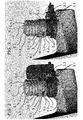
- Figure 1 shows the mirror when the case is not present in order to have visual access to the internal components of the mirror.
- a base (1) projecting from one side of the vehicle for supporting the folding mirror.
- the base (1) there is an upright pivot (1.1) having three vertical grooves on the lateral surface of said pivot (1.1) which are used as guiding means (1.1.1) for a first ring (3).
- the first ring (3) has an internal radial abutment (3) per groove adapted to slide along the groove (1.1.1) limiting said first ring (3) to an axial displacement.
- This first ring (3) has two concentric annular sectors, an internal annular sector which is hollow and comprises in this embodiment three projections in whose bottom surface there is, centered, a housing resulting from two double-wedged projections (3.1); and an external annular sector that, in this embodiment, has three holes (3.4).
- the housing resulting from the two double-wedged projections (3.1) is adapted to house a flange (5.1) located in the upper part of a rotatable crown-wheel (5), extended upwardly under the internal annular sector of the first ring (3).
- the rotatable crown-wheel (5) is also extended along the axis (X) surrounding the pivot (1.1).
- the rotatable crown-wheel (5) is adapted to engage with the pinion gear (not shown) of the motor (6.2).
- the rotatable crown-wheel (5) is rotationally integral with the base (1) because its flange (5.1) is housed in the housing resulting from the two double-wedged projections (3.1) of the first ring (3) which cannot rotate.
- the motor (6.2) When the motor (6.2) is energized, its pinion gear drives the rotation of the support of the motor (6.2) and therefore the rotatable frame (6) while the rotatable crown-wheel (5) and the first ring (3) is rotationally integral with the pivot (1.1) which is fixed onto the base (1).
- the first ring (3) is rotationally integral with the crown-wheel (5) unless the torque between the rotatable crown-wheel (5) and the first ring (3) reaches a predetermined value according to the force of the spring (2) as it will be disclosed below.
- Figures 2 and 3 also show a second ring (4) extended along the same axis (X) surrounding the pivot (1.1) and located under the first ring (3) axially guided with respect to the first ring (3) by means of second axial guiding means (3.4, 4.1).
- These second guiding means are three stems (4.1) located over the second ring (4), which enter into three corresponding holes (3.4) of the second ring (3).
- the first ring (3) has a first lower abutment (3.2) defining the minimum distance between the first ring (3) and the second ring (4).
- This second ring (4) comprises at least a second lower wedged abutment (4.2), three in this embodiment, adapted to be housed in a wedged cavity (6.1.1) located over an annular sector surface (6.1) of the portion of the rotatable frame (6) which is surrounding the second ring (4).
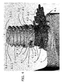
- Figure 4 shows the support of the motor (6.2) according to the unfolded position and the flange (5.1) of the rotatable crown-wheel (5) housed in the housing resulting from the two double-wedged projections (3.1) of the first ring (3).
- Figure 5 shows the final angular position of the support of the motor (6.2) when the motor (6.2) has been energized which is also the final angular position of the rotatable frame (6) not shown in order to have visual access to the two internal rings (3, 4).
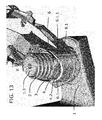
- Figure 13 shows the same position as figure 5 but in this figure the rotatable frame (6) is represented.
- the top view allows having visual access to the annular sector surface (6.1) with the wedged cavity (6.1.1) because due to the rotation of the rotatable frame (6) the second lower wedged abutment (4.2) of the second ring (4) has gone out of the wedged cavity (6.1.1).
- the wedged shape of the cavity (6.1.1) and the wedged shape of the second lower wedged abutment (4.2) of the second ring (4) raise the second ring (4) until said second lower wedged abutment (4.2) reaches the upper surface of the annular sector surface (6.1).
- FIG. 5 The final angular position of the folding mirror shown in figure 5 is the position reached after a powered movement.
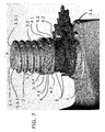
- Figures 6 , 7 and 8 are a sequence of angular positions when the user unfolds the mirror manually.
- the user unfolds the mirror exerting a force over the rotatable frame (6) and; therefore, over the rotatable crown-wheel (5) because motor and the rotatable crown-wheel (5) are rotationally integral since the motor has not been energized.
- the shape of the housing resulting from the two double-wedged projections (3.1), the shape of the flange (5.1) and the spring (2) determines the maximum torque between the first ring (3) and the rotatable crown-wheel (5) before the flange (5.1) comes out of the housing. When the force exceeds the maximum torque the housing cannot hold the flange (5.1) raising the first ring (3) and compressing the spring (2).
- the rotatable crown-wheel (5), the motor (6.2) and the rotatable frame (6) integrally rotate.
- the first ring is elevated allowing the flange (5.1) to come out of the housing.
- this flange is partially hidden by the stem (4.1) of the second ring (4).
- Figure 7 is the final angular position wherein:
- the angular position given by this second detent is in the same angular position as the one given by the first detent, provided when the folding/unfolding movement is driven by the motor.
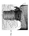
- Figures 8 , 9 and 10 show the sequence of the reset of the device that takes place when the motor is energized, wherein the flange (5.1) recovers its position coming back to the housing resulting from the two double-wedged projections (3.1) of the first ring (3).
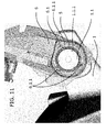
- the rotatable frame (6) has been sectioned providing visual access to the internal part of the device such that the annular sector surface (6.1) is shown as an integral part of the rotatable frame (6).
- This annular sector surface (6.1) is extended inwardly around the package comprised by the set of rings (3, 4) providing a surface with wedged cavities (6.1.1), at least one wedged cavity (6.1.1) per wedged abutment (4.2) of the second ring (4), where the wedged abutment/abutments (4.2) rest/s.
- each wedged abutment (4.2) and the corresponding wedged cavity (6.1.1) where the abutment is housed provides the retention of the mirror through the second ring (4). This retention is overcome when the user manually folds the mirror because each wedged abutment (4.2) comes out of its wedge cavity (6.1.1) against the force provided by the spring (2).
- the set of pairs abutment (4.2)/cavity (6.1.1) is equally distributed.
Landscapes
- Engineering & Computer Science (AREA)
- Multimedia (AREA)
- Mechanical Engineering (AREA)
- Rear-View Mirror Devices That Are Mounted On The Exterior Of The Vehicle (AREA)
Priority Applications (1)
| Application Number | Priority Date | Filing Date | Title |
|---|---|---|---|
| EP12382326.2A EP2698280B1 (de) | 2012-08-14 | 2012-08-14 | Faltspiegel mit Doppelarretierung |
Applications Claiming Priority (1)
| Application Number | Priority Date | Filing Date | Title |
|---|---|---|---|
| EP12382326.2A EP2698280B1 (de) | 2012-08-14 | 2012-08-14 | Faltspiegel mit Doppelarretierung |
Publications (2)
| Publication Number | Publication Date |
|---|---|
| EP2698280A1 true EP2698280A1 (de) | 2014-02-19 |
| EP2698280B1 EP2698280B1 (de) | 2015-08-19 |
Family
ID=46799182
Family Applications (1)
| Application Number | Title | Priority Date | Filing Date |
|---|---|---|---|
| EP12382326.2A Active EP2698280B1 (de) | 2012-08-14 | 2012-08-14 | Faltspiegel mit Doppelarretierung |
Country Status (1)
| Country | Link |
|---|---|
| EP (1) | EP2698280B1 (de) |
Cited By (2)
| Publication number | Priority date | Publication date | Assignee | Title |
|---|---|---|---|---|
| CN106985755A (zh) * | 2015-09-29 | 2017-07-28 | 法可镜子股份公司 | 用于机动车辆的折叠后视镜组件 |
| US11279285B2 (en) * | 2018-07-16 | 2022-03-22 | Motherson Innovations Company Limited | Exterior mirror with reduced folding noise |
Citations (4)
| Publication number | Priority date | Publication date | Assignee | Title |
|---|---|---|---|---|
| EP1239178A2 (de) * | 2001-03-08 | 2002-09-11 | Ntn Corporation | Rückwärtsfahrende Sperrkupplung |
| DE10300942B3 (de) * | 2003-01-13 | 2004-07-22 | Em Kunststofftechnik Gmbh | Vorrichtung zum mechanischen Verstellen eines Halters für einen Kraftfahrzeugaußenspiegel |
| EP2230131A1 (de) * | 2008-08-05 | 2010-09-22 | SMR Patents S.à.r.l. | Zusammenklappbare Rückspiegeleinheit für ein Fahrzeug |
| US20100296185A1 (en) * | 2009-05-21 | 2010-11-25 | Murakami Corporation | Shaft structure of retractable outer mirror |
-
2012
- 2012-08-14 EP EP12382326.2A patent/EP2698280B1/de active Active
Patent Citations (4)
| Publication number | Priority date | Publication date | Assignee | Title |
|---|---|---|---|---|
| EP1239178A2 (de) * | 2001-03-08 | 2002-09-11 | Ntn Corporation | Rückwärtsfahrende Sperrkupplung |
| DE10300942B3 (de) * | 2003-01-13 | 2004-07-22 | Em Kunststofftechnik Gmbh | Vorrichtung zum mechanischen Verstellen eines Halters für einen Kraftfahrzeugaußenspiegel |
| EP2230131A1 (de) * | 2008-08-05 | 2010-09-22 | SMR Patents S.à.r.l. | Zusammenklappbare Rückspiegeleinheit für ein Fahrzeug |
| US20100296185A1 (en) * | 2009-05-21 | 2010-11-25 | Murakami Corporation | Shaft structure of retractable outer mirror |
Cited By (3)
| Publication number | Priority date | Publication date | Assignee | Title |
|---|---|---|---|---|
| CN106985755A (zh) * | 2015-09-29 | 2017-07-28 | 法可镜子股份公司 | 用于机动车辆的折叠后视镜组件 |
| CN106985755B (zh) * | 2015-09-29 | 2021-07-27 | 法可镜子股份公司 | 用于机动车辆的折叠后视镜组件 |
| US11279285B2 (en) * | 2018-07-16 | 2022-03-22 | Motherson Innovations Company Limited | Exterior mirror with reduced folding noise |
Also Published As
| Publication number | Publication date |
|---|---|
| EP2698280B1 (de) | 2015-08-19 |
Similar Documents
| Publication | Publication Date | Title |
|---|---|---|
| JP6535814B2 (ja) | 車両用の外部視覚ユニットのための調節装置 | |
| KR101991136B1 (ko) | 외부 미러의 그룹 | |
| JP4249818B2 (ja) | 外部バック・ミラー | |
| EP1754630B1 (de) | Absenkmechanismus für die aussenrückspiegel von kraftfahrzeugen | |
| EP2698280B1 (de) | Faltspiegel mit Doppelarretierung | |
| RU2601991C2 (ru) | Электрически вращательный регулирующий блок, в частности, для непрямых визуальных систем для транспортных средств | |
| US20020159824A1 (en) | Mechanism for regulating collapsible elements | |
| CN107554756B (zh) | 具有转动式驱动致动器的飞机起落架 | |
| EP3022832B1 (de) | Antriebsvorrichtung für einen elektrisch klappbaren seitenspiegel für ein fahrzeug | |
| JPS6227478Y2 (de) | ||
| JP2013052779A (ja) | 展開車輪 | |
| JP6419978B2 (ja) | 車両のトランスミッションのためのギアシフトアセンブリ | |
| WO2015173090A1 (en) | Fold rearview mirror assembly for motor vehicles | |
| CN108584777A (zh) | 剪叉式液压升降机 | |
| US10703280B2 (en) | Actuator mechanism for a fold rear-view mirror assembly | |
| JP2017505257A (ja) | タイヤのグリップを高める装置 | |
| AU2017100937A4 (en) | A foldable arm configuration of an unmanned aerial vehicle | |
| WO2012152961A1 (es) | Gato hidráulico con enclavamientq | |
| EP1349748A1 (de) | Gelenkstellglied für einen kotflügelspiegel eines kraftfahrzeugs | |
| CN104118340A (zh) | 用于汽车座椅的电动调角器 | |
| EP2433894B1 (de) | Hydraulischer hebebock mit verriegelung | |
| ITTV20110139A1 (it) | Motoriduttore tubolare con supporto di fissaggio | |
| CN106476915B (zh) | 备胎升降器 | |
| US10035459B2 (en) | Rear view mirror assembly for motor vehicles | |
| CN103670115B (zh) | 手动电动一体齿轮箱结构及车辆 |
Legal Events
| Date | Code | Title | Description |
|---|---|---|---|
| AK | Designated contracting states |
Kind code of ref document: A1 Designated state(s): AL AT BE BG CH CY CZ DE DK EE ES FI FR GB GR HR HU IE IS IT LI LT LU LV MC MK MT NL NO PL PT RO RS SE SI SK SM TR |
|
| AX | Request for extension of the european patent |
Extension state: BA ME |
|
| PUAI | Public reference made under article 153(3) epc to a published international application that has entered the european phase |
Free format text: ORIGINAL CODE: 0009012 |
|
| 17P | Request for examination filed |
Effective date: 20140721 |
|
| RBV | Designated contracting states (corrected) |
Designated state(s): AL AT BE BG CH CY CZ DE DK EE ES FI FR GB GR HR HU IE IS IT LI LT LU LV MC MK MT NL NO PL PT RO RS SE SI SK SM TR |
|
| RIC1 | Information provided on ipc code assigned before grant |
Ipc: B60R 1/074 20060101AFI20140909BHEP Ipc: B60R 1/076 20060101ALI20140909BHEP |
|
| GRAP | Despatch of communication of intention to grant a patent |
Free format text: ORIGINAL CODE: EPIDOSNIGR1 |
|
| INTG | Intention to grant announced |
Effective date: 20141017 |
|
| GRAP | Despatch of communication of intention to grant a patent |
Free format text: ORIGINAL CODE: EPIDOSNIGR1 |
|
| INTG | Intention to grant announced |
Effective date: 20150312 |
|
| GRAS | Grant fee paid |
Free format text: ORIGINAL CODE: EPIDOSNIGR3 |
|
| GRAA | (expected) grant |
Free format text: ORIGINAL CODE: 0009210 |
|
| AK | Designated contracting states |
Kind code of ref document: B1 Designated state(s): AL AT BE BG CH CY CZ DE DK EE ES FI FR GB GR HR HU IE IS IT LI LT LU LV MC MK MT NL NO PL PT RO RS SE SI SK SM TR |
|
| REG | Reference to a national code |
Ref country code: GB Ref legal event code: FG4D |
|
| REG | Reference to a national code |
Ref country code: CH Ref legal event code: EP |
|
| REG | Reference to a national code |
Ref country code: IE Ref legal event code: FG4D |
|
| REG | Reference to a national code |
Ref country code: AT Ref legal event code: REF Ref document number: 743553 Country of ref document: AT Kind code of ref document: T Effective date: 20150915 |
|
| REG | Reference to a national code |
Ref country code: DE Ref legal event code: R096 Ref document number: 602012009743 Country of ref document: DE |
|
| REG | Reference to a national code |
Ref country code: AT Ref legal event code: MK05 Ref document number: 743553 Country of ref document: AT Kind code of ref document: T Effective date: 20150819 |
|
| REG | Reference to a national code |
Ref country code: LT Ref legal event code: MG4D |
|
| REG | Reference to a national code |
Ref country code: NL Ref legal event code: MP Effective date: 20150819 |
|
| PG25 | Lapsed in a contracting state [announced via postgrant information from national office to epo] |
Ref country code: FI Free format text: LAPSE BECAUSE OF FAILURE TO SUBMIT A TRANSLATION OF THE DESCRIPTION OR TO PAY THE FEE WITHIN THE PRESCRIBED TIME-LIMIT Effective date: 20150819 Ref country code: NO Free format text: LAPSE BECAUSE OF FAILURE TO SUBMIT A TRANSLATION OF THE DESCRIPTION OR TO PAY THE FEE WITHIN THE PRESCRIBED TIME-LIMIT Effective date: 20151119 Ref country code: LT Free format text: LAPSE BECAUSE OF FAILURE TO SUBMIT A TRANSLATION OF THE DESCRIPTION OR TO PAY THE FEE WITHIN THE PRESCRIBED TIME-LIMIT Effective date: 20150819 Ref country code: LV Free format text: LAPSE BECAUSE OF FAILURE TO SUBMIT A TRANSLATION OF THE DESCRIPTION OR TO PAY THE FEE WITHIN THE PRESCRIBED TIME-LIMIT Effective date: 20150819 |
|
| PG25 | Lapsed in a contracting state [announced via postgrant information from national office to epo] |
Ref country code: IS Free format text: LAPSE BECAUSE OF FAILURE TO SUBMIT A TRANSLATION OF THE DESCRIPTION OR TO PAY THE FEE WITHIN THE PRESCRIBED TIME-LIMIT Effective date: 20151219 Ref country code: ES Free format text: LAPSE BECAUSE OF FAILURE TO SUBMIT A TRANSLATION OF THE DESCRIPTION OR TO PAY THE FEE WITHIN THE PRESCRIBED TIME-LIMIT Effective date: 20150819 Ref country code: PL Free format text: LAPSE BECAUSE OF FAILURE TO SUBMIT A TRANSLATION OF THE DESCRIPTION OR TO PAY THE FEE WITHIN THE PRESCRIBED TIME-LIMIT Effective date: 20150819 Ref country code: SE Free format text: LAPSE BECAUSE OF FAILURE TO SUBMIT A TRANSLATION OF THE DESCRIPTION OR TO PAY THE FEE WITHIN THE PRESCRIBED TIME-LIMIT Effective date: 20150819 Ref country code: PT Free format text: LAPSE BECAUSE OF FAILURE TO SUBMIT A TRANSLATION OF THE DESCRIPTION OR TO PAY THE FEE WITHIN THE PRESCRIBED TIME-LIMIT Effective date: 20151221 Ref country code: AT Free format text: LAPSE BECAUSE OF FAILURE TO SUBMIT A TRANSLATION OF THE DESCRIPTION OR TO PAY THE FEE WITHIN THE PRESCRIBED TIME-LIMIT Effective date: 20150819 Ref country code: RS Free format text: LAPSE BECAUSE OF FAILURE TO SUBMIT A TRANSLATION OF THE DESCRIPTION OR TO PAY THE FEE WITHIN THE PRESCRIBED TIME-LIMIT Effective date: 20150819 |
|
| PG25 | Lapsed in a contracting state [announced via postgrant information from national office to epo] |
Ref country code: NL Free format text: LAPSE BECAUSE OF FAILURE TO SUBMIT A TRANSLATION OF THE DESCRIPTION OR TO PAY THE FEE WITHIN THE PRESCRIBED TIME-LIMIT Effective date: 20150819 |
|
| PG25 | Lapsed in a contracting state [announced via postgrant information from national office to epo] |
Ref country code: DK Free format text: LAPSE BECAUSE OF FAILURE TO SUBMIT A TRANSLATION OF THE DESCRIPTION OR TO PAY THE FEE WITHIN THE PRESCRIBED TIME-LIMIT Effective date: 20150819 Ref country code: EE Free format text: LAPSE BECAUSE OF FAILURE TO SUBMIT A TRANSLATION OF THE DESCRIPTION OR TO PAY THE FEE WITHIN THE PRESCRIBED TIME-LIMIT Effective date: 20150819 Ref country code: CZ Free format text: LAPSE BECAUSE OF FAILURE TO SUBMIT A TRANSLATION OF THE DESCRIPTION OR TO PAY THE FEE WITHIN THE PRESCRIBED TIME-LIMIT Effective date: 20150819 Ref country code: SK Free format text: LAPSE BECAUSE OF FAILURE TO SUBMIT A TRANSLATION OF THE DESCRIPTION OR TO PAY THE FEE WITHIN THE PRESCRIBED TIME-LIMIT Effective date: 20150819 Ref country code: IT Free format text: LAPSE BECAUSE OF FAILURE TO SUBMIT A TRANSLATION OF THE DESCRIPTION OR TO PAY THE FEE WITHIN THE PRESCRIBED TIME-LIMIT Effective date: 20150819 |
|
| REG | Reference to a national code |
Ref country code: DE Ref legal event code: R097 Ref document number: 602012009743 Country of ref document: DE |
|
| PG25 | Lapsed in a contracting state [announced via postgrant information from national office to epo] |
Ref country code: RO Free format text: LAPSE BECAUSE OF FAILURE TO SUBMIT A TRANSLATION OF THE DESCRIPTION OR TO PAY THE FEE WITHIN THE PRESCRIBED TIME-LIMIT Effective date: 20150819 |
|
| PLBE | No opposition filed within time limit |
Free format text: ORIGINAL CODE: 0009261 |
|
| STAA | Information on the status of an ep patent application or granted ep patent |
Free format text: STATUS: NO OPPOSITION FILED WITHIN TIME LIMIT |
|
| 26N | No opposition filed |
Effective date: 20160520 |
|
| PG25 | Lapsed in a contracting state [announced via postgrant information from national office to epo] |
Ref country code: SI Free format text: LAPSE BECAUSE OF FAILURE TO SUBMIT A TRANSLATION OF THE DESCRIPTION OR TO PAY THE FEE WITHIN THE PRESCRIBED TIME-LIMIT Effective date: 20150819 |
|
| PG25 | Lapsed in a contracting state [announced via postgrant information from national office to epo] |
Ref country code: BE Free format text: LAPSE BECAUSE OF FAILURE TO SUBMIT A TRANSLATION OF THE DESCRIPTION OR TO PAY THE FEE WITHIN THE PRESCRIBED TIME-LIMIT Effective date: 20150819 |
|
| PG25 | Lapsed in a contracting state [announced via postgrant information from national office to epo] |
Ref country code: MC Free format text: LAPSE BECAUSE OF FAILURE TO SUBMIT A TRANSLATION OF THE DESCRIPTION OR TO PAY THE FEE WITHIN THE PRESCRIBED TIME-LIMIT Effective date: 20150819 |
|
| REG | Reference to a national code |
Ref country code: CH Ref legal event code: PL |
|
| GBPC | Gb: european patent ceased through non-payment of renewal fee |
Effective date: 20160814 |
|
| PG25 | Lapsed in a contracting state [announced via postgrant information from national office to epo] |
Ref country code: LI Free format text: LAPSE BECAUSE OF NON-PAYMENT OF DUE FEES Effective date: 20160831 Ref country code: CH Free format text: LAPSE BECAUSE OF NON-PAYMENT OF DUE FEES Effective date: 20160831 |
|
| REG | Reference to a national code |
Ref country code: FR Ref legal event code: ST Effective date: 20170428 |
|
| REG | Reference to a national code |
Ref country code: IE Ref legal event code: MM4A |
|
| PG25 | Lapsed in a contracting state [announced via postgrant information from national office to epo] |
Ref country code: GB Free format text: LAPSE BECAUSE OF NON-PAYMENT OF DUE FEES Effective date: 20160814 Ref country code: IE Free format text: LAPSE BECAUSE OF NON-PAYMENT OF DUE FEES Effective date: 20160814 Ref country code: FR Free format text: LAPSE BECAUSE OF NON-PAYMENT OF DUE FEES Effective date: 20160831 |
|
| PG25 | Lapsed in a contracting state [announced via postgrant information from national office to epo] |
Ref country code: LU Free format text: LAPSE BECAUSE OF NON-PAYMENT OF DUE FEES Effective date: 20160814 |
|
| PG25 | Lapsed in a contracting state [announced via postgrant information from national office to epo] |
Ref country code: SM Free format text: LAPSE BECAUSE OF FAILURE TO SUBMIT A TRANSLATION OF THE DESCRIPTION OR TO PAY THE FEE WITHIN THE PRESCRIBED TIME-LIMIT Effective date: 20150819 Ref country code: HU Free format text: LAPSE BECAUSE OF FAILURE TO SUBMIT A TRANSLATION OF THE DESCRIPTION OR TO PAY THE FEE WITHIN THE PRESCRIBED TIME-LIMIT; INVALID AB INITIO Effective date: 20120814 Ref country code: CY Free format text: LAPSE BECAUSE OF FAILURE TO SUBMIT A TRANSLATION OF THE DESCRIPTION OR TO PAY THE FEE WITHIN THE PRESCRIBED TIME-LIMIT Effective date: 20150819 |
|
| PG25 | Lapsed in a contracting state [announced via postgrant information from national office to epo] |
Ref country code: HR Free format text: LAPSE BECAUSE OF FAILURE TO SUBMIT A TRANSLATION OF THE DESCRIPTION OR TO PAY THE FEE WITHIN THE PRESCRIBED TIME-LIMIT Effective date: 20150819 Ref country code: GR Free format text: LAPSE BECAUSE OF FAILURE TO SUBMIT A TRANSLATION OF THE DESCRIPTION OR TO PAY THE FEE WITHIN THE PRESCRIBED TIME-LIMIT Effective date: 20150819 Ref country code: MK Free format text: LAPSE BECAUSE OF FAILURE TO SUBMIT A TRANSLATION OF THE DESCRIPTION OR TO PAY THE FEE WITHIN THE PRESCRIBED TIME-LIMIT Effective date: 20150819 Ref country code: TR Free format text: LAPSE BECAUSE OF FAILURE TO SUBMIT A TRANSLATION OF THE DESCRIPTION OR TO PAY THE FEE WITHIN THE PRESCRIBED TIME-LIMIT Effective date: 20150819 Ref country code: MT Free format text: LAPSE BECAUSE OF NON-PAYMENT OF DUE FEES Effective date: 20160831 |
|
| PG25 | Lapsed in a contracting state [announced via postgrant information from national office to epo] |
Ref country code: BG Free format text: LAPSE BECAUSE OF FAILURE TO SUBMIT A TRANSLATION OF THE DESCRIPTION OR TO PAY THE FEE WITHIN THE PRESCRIBED TIME-LIMIT Effective date: 20150819 |
|
| PG25 | Lapsed in a contracting state [announced via postgrant information from national office to epo] |
Ref country code: AL Free format text: LAPSE BECAUSE OF FAILURE TO SUBMIT A TRANSLATION OF THE DESCRIPTION OR TO PAY THE FEE WITHIN THE PRESCRIBED TIME-LIMIT Effective date: 20150819 |
|
| PGFP | Annual fee paid to national office [announced via postgrant information from national office to epo] |
Ref country code: DE Payment date: 20250827 Year of fee payment: 14 |